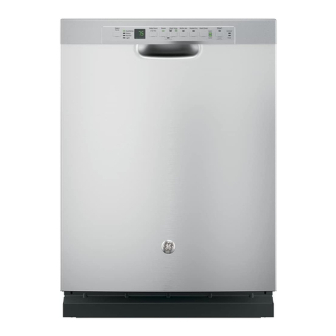
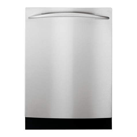
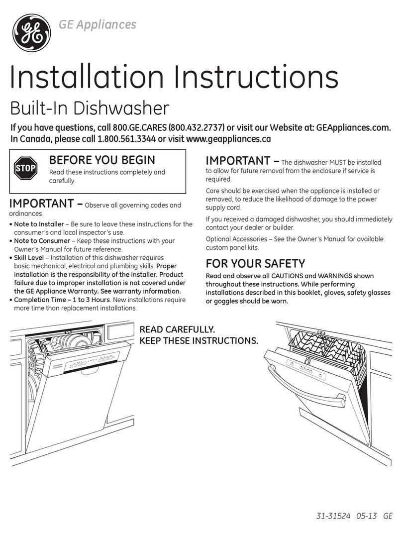
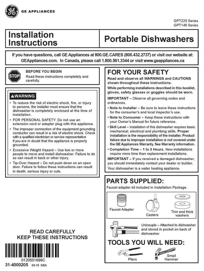
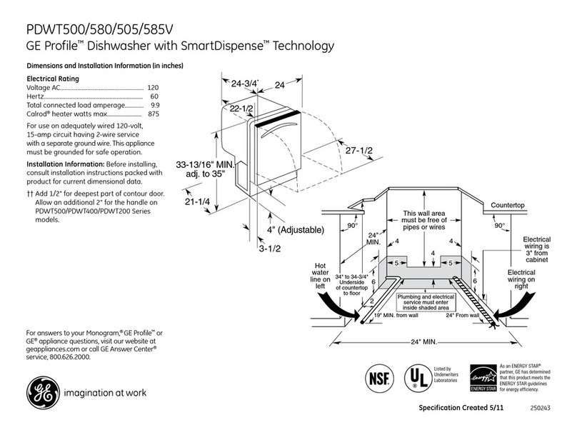
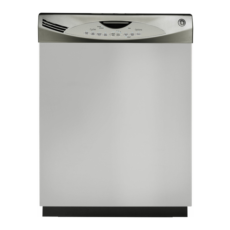
GE WX09X70910 User manual

Installation
Instructions Dishwasher
If you have questions, call 1-800-561-3344 or visit our website at: www.GEAppliances.ca
IMPORTANT– The dishwasher
MUST be installed to allow for future removal from
the enclosure if service is required.
If you received a damaged dishwasher, you should
immediately contact your dealer or builder.
FOR YOUR SAFETY
Read and observe all CAUTIONS and WARNINGS
shown throughout these instructions. While performing
installations described in this booklet, gloves, safety
glasses or goggles should be worn.
BEFORE YOU BEGIN
Read these instructions completely and
carefully.
IMPORTANT– Observe all
governing codes and ordinances.
•Note to Installer – Be sure to leave these instructions
for the consumer’s and local inspector’s use.
•Note to Consumer – Keep these instructions with your
Owner’s Manual for future reference.
•Skill Level – Installation of this dishwasher requires
basic mechanical and electrical skills. Proper
installation is the responsibility of the installer.
Product failure due to improper installation is not
covered under the GE Appliance Warranty.
•Completion Time – 1 to 3 Hours. New installations
require more time than replacement installations.
READ CAREFULLY.
KEEP THESE INSTRUCTIONS.
WARNING
To reduce the risk of electrical shock, fire,
or injury to persons, the installer must
ensure that the dishwasher is completely
enclosed at the time of installation.
If you have an installation problem, contact your
dealer or installer. You are responsible for providing
adequate electrical,exhaustingand otherconnecting
facilities.
La section française commence après la section anglaise
FOR INSTALLATION INSTRUCTIONS
OF PORTABLE MODELS, REFER TO
PAGE 13.

TOOLS YOU WILL NEED:
Phillips head screwdriver
5/16" and 1/4" nutdriver
6" Adjustable wrench
Level
Carpenters square
Measuring tape
Safety glasses
Flashlight
Bucket to catch water when flushing the line
Gloves
For New Installations Only:
Tubing cutter
Drill and appropriate bits
Hole saw set
Phillips
Head
Screwdriver
Installation Preparation
PARTS SUPPLIED:
Two #8 Phillips flat head wood screws, 5/8" long
to secure dishwasher to underside of countertop
(in literature package).
Two Phillips head, color matched toekick screws
(in literature package).
MATERIALS YOU WILL NEED :
Ferrule, compression nut and 90° Elbow (3/8"NPT external
thread on one end, opposite end sized to fit water supply)
Thread seal tape
UL Listed wire nuts (3)
Materials For New Installations Only:
Air gap for drain hose, if required
Waste tee for house plumbing, if applicable
Electrical cable or power cord, if applicable
Screw type hose clamps
Strain relief for electrical connection.
Hand shut-off valve
Water line 3/8" min. copper
Coupler for extending drain line, if applicable
90° Elbow,
Ferrule and
Compression Nut
Wire Nuts (3)
Waste Tee
Electrical Cable
(or Power Cord, if applicable) Hot Water line
Screw Type
Hose Clamps
Coupler
Hand
Shut-Off
Valve
2 Wood Screws
Hole Saw Set
Measuring Tape
Tubing Cutter
Drill and Bits
1/4"
and 5/16" Nut-
driver
Safety Glasses
6" Adjustable
Wrench
Bucket
Flashlight
Gloves
Carpenters
Square
Level
2
Thread
Seal Tape
Air Gap Strain Relief
2 Color Matched
Toekick Screws

Installation Preparation
3
PREPARE DISHWASHERENCLOSURE
•
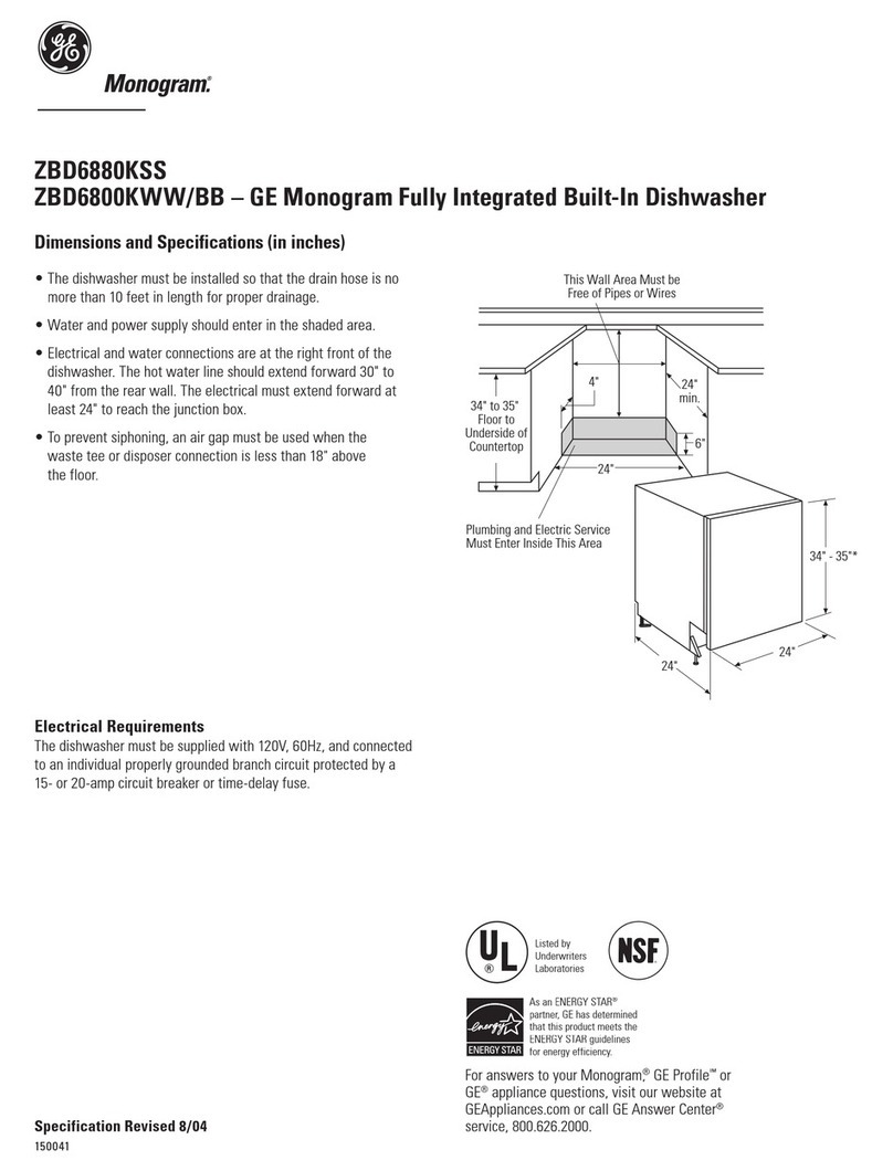
The rough cabinet opening must be at least 24" deep and
17-5/8" to 18" wide for 18" wide models, or 23-5/8" to 24" wide
for 24" wide models. The opening should be 35" max. height.
DRAIN REQUIREMENTS
•Follow local codes and ordinances.
•Do not exceed 10 feet distance to drain.
•Do not connect drain lines from other devices
to the dishwasher drain hose.
•Dishwasher must be connected to waste line with an
air gap (not supplied) or 32" minimum high drain loop,
depending on local codes and ordinances to prevent
back flow into the dishwasher.
•Air gap must be used if waste tee or disposer connection
is less than 18" above the floor to prevent siphoning.
DRAIN PREPARATION
The type of drain installation depends on answers to
the following questions:
Do local codes or ordinances require an air gap?
Will waste tee or disposer connection be less than
18" above the floor?
Will installation have a drain loop less than 32"
above floor?
If the answer to ANY of the 3 questions above is YES,
Method 1 MUST be used. Otherwise either Method 1
or Method 2 may be used. Figure C or Figure D.
CAUTION:
An air gap MUST BE USED if the drain hose is connected
to waste tee or disposer lower than 18" above the floor.
Failure to provide the proper drain connection height
with air gap or 32" minimum, high drain loop will result in
improper draining of the dishwasher.
Figure B
Figure C
Figure D
Note:ADA installation, (32-1/2") beneath 34" high counter-
tops may be accomplished by adjusting the toekick and leveling
legs.
Install waste tee or disposer and air gap according to
manufacturer’s instructions.
CABINET PREPARATION
• Drill a 1-1/2" dia. hole in the cabinet wall within the
shaded areas shown in Figure A for the drain hose
connection. The hole should be smooth with no sharp
edges.
Method 1 – Air Gap with Waste Tee or Disposer
Method 2 – High Drain with Waste Tee or Disposer
Provide a method to attach drain hose to underside of
countertop.
Cabinets
Square
and
Plumb
Floor MUST
be Even with
Room Floor. Plumbingand Electric Service
Must EnterShaded Area
34" to 35"
Underside of
Countertop
to Floor
24"
Min.
17-5/8" or 23-5/8" Min.
18" or 24" Max.
4"
6"
Clearance for Door
Opening 2" Minimum
Countertop
Dishwasher
25-5/8"
18"
Min.
32"
Min.
32"
Min.
18"
Min.
•The dishwasher must be installed so that drain hose is
no more than 10 feet in length for proper drainage.
•The dishwasher must be fully enclosed on the top,
sides and back, and must not support any part of the
enclosure.
CLEARANCES: When
installed into a corner,
allow 2" min. clearance
between dishwasher and
adjacent cabinet, wall or
other appliances. Allow
25-5/8" min. clearance
from the front of the dish-
washer for door opening.
Figure B
Figure A

Installation Preparation
4
Cabinet Preparation & Wire Routing
• The wiring may enter the opening from either side,
rear or the floor within the shaded area.
• Cut a 1-1/2" max. dia. hole to admit the electrical cable.
The hole must be free of sharp edges. If the cabinet
wall is metal, the hole edge must be covered with a
bushing.
• Cable direct connections may pass through the same
hole as the drain hose and hot water line, if convenient.
If cabinet wall is metal, the hole edge must be covered
with a bushing. NOTE: Power cords with plug must
pass through a separate hole.
Electrical Connection to Dishwasher
Electrical connection is on the right front of dishwasher.
• For cable direct connections the cable must be routed
as shown in Figure E. Cable must extend a minimum of
24" from the rear wall.
• For power cord connections, install a 3-prong grounding
type receptacle. The power-supply receptacle for the
appliance shall be installed in a cabinet or on a wall
adjacent to the undercounter space in which the
appliance is to be installed.
Figure E
WARNING
FOR PERSONAL SAFETY: Remove house
fuse or open circuit breaker before
beginning installation. Do not use an
extension cord or adapter plug with this
appliance.
PREPARE ELECTRICAL WIRING
Electrical Requirements
• This appliance must be supplied with 120V, 60 Hz., and
connected to an individual properly grounded branch
circuit, protected by a 15 or 20 ampere circuit breaker
or time delay fuse.
• Wiring must be 2 wire with ground.
• If the electrical supply does not meet the above
requirements, call a licensed electrician before
proceeding.
Grounding Instructions – Cable Direct
This appliance must be connected to a grounded metal,
permanent wiring system, or an equipment grounding
conductor must be run with the circuit conductors and
be connected to the equipment grounding terminal or
lead on the appliance.
Grounding Instructions – Power Cord Models
This appliance must be grounded. In the event of a mal-
function or breakdown, grounding will reduce the risk of
electrical shock by providing a path of least resistance
for electric current. The plug must be plugged into an
appropriate outlet that is installed
and grounded in accordance with local codes and
ordinances.
WARNING
The improper connection of the
equipment grounding conductor can
result in a risk of electric shock. Check
with a qualified electrician or service
representative if you are in doubt that
the appliance is properly grounded.
White
24"
from Wall
3"
from
Cabinet
Ground
Black
1-1/2"Dia.
Hole(Max.)
Installation Instructions
5
PREPARE HOT WATER LINE
• The line may enter from either side, rear or floor
within the shaded area shown in Figure F.
• The line may pass through the same hole as the
electrical cable and drain hose. Or, cut an additional
1-1/2" dia. hole to accommodate the water line.
If power cord with plug is used, water line must not
pass through power cord hole.
Figure F
Water Line Connection
• Turn off the water supply.
• Install a hand shut-off valve in an accessible location,
such as under the sink. (Optional, but strongly
recommended and may be required by local codes.)
• Water connection is on the left side of the dishwasher.
Install the hot water inlet line, using no less than 3/8"
O.D. copper tubing. Route the line as shown in Figure F
and extend forward at least 18" from rear wall.
• Adjust water heater for 120°F to 150°F temperature.
• Flush water line to clean out debris.
• The hot water supply line pressure must be 20-120 PSI.
CAUTION:
Opening the door will cause the dishwasher
to tip forward. Do not open the door until you are ready
to install the dishwasher. If it is
necessary to open the door, hold
the top of the dishwasher securely
with one hand and hold the door
with the other hand.
• Open the door slowly, if the door drops when
released, increase spring tension. If the door closes
when released, decrease tension.
• Pull the spring adjustment pin out of the holes, insert
in the next highest or lowest hole and test again.
• Adjust both door springs to the same tension.
• Continue moving the spring pin until door is balanced.
STEP 1 CHECK DOOR BALANCE
To check the door balance, hold the top of the dish-
washer firmly.
Figure G
BEFORE YOU BEGIN
Locate and set aside the package containing
2 Phillips head countertop mounting screws
and 2 additional toekick screws (located in
the literature package).
Cabinet Face
Shut-off
Valve
3" From Floor
18" From Wall
4"
From
Cabinet
1-1/2" Dia.
Hole
Hot
Increase
Decrease

White
Ground Black
Check That White, Black and
Green Dishwasher Wires Are Threaded
Thru Hole in Back
Remove
Junction Box
Cover
Insert Power
Cord Wires Thru
Strain Relief
and Tighten
Use UL Listed
Wire Nuts
A
C
B
D
Installation Instructions
6
•Do not over tighten 90° elbow, water valve bracket
could bend or water valve fitting could break.
•Position the end of the elbow to face the rear of the
dishwasher.
STEP 5 INSTALL 90° ELBOW
•Wrap 90° elbow with thread seal tape. Do not use
plumber's putty.
•Install a 90° elbow onto the water valve.
Figure L
Figure J
STEP 3 REMOVE TOEKICK
• Remove the 4 toekick screws. Lift off the 2 piece
toekick.
•Measure installation height and dishwasher height.
Extend leveling legs out from the dishwasher base,
1/4" less than installation height.
Figure H
STEP 2 ADJUST LEVELING LEGS
•Move the dishwasher close to the installation loca-
tion and lay it on its back.
STEP 4 INSTALL POWER CORD
Skip this step if dishwasher will be direct wired. Use
power cord kit WX09X70910 available for purchase from
an authorized GE Appliances dealer. The power cord and
connections must comply with the National Electrical
Code, Section 422 and/or local codes and ordinances.
• Recommended power cord length is 54" min. and
64" max.
Figure K
Adjust to
Installation
Height
• Connect incoming
power cord white (or ribbed)
to dishwasher white, black
(or smooth) to black and ground to dishwasher green
wire. Use UL listed wire nuts of appropriate size.
• Replace junction box cover. Be sure wires are not
pinched under the cover.
Remove
Toekick
Screws
90
Elbow
Fill
Hose
Thread
Seal Tape
Water
Valve
Bracket

Power Cord
(If Used)
Insulation
Blanket Water
Line
House
Wiring
Drain
Hose
Maximum
Drain Hose
Length 10'
Installation Instructions
7
STEP 8 SLIDE DISHWASHER
PARTIALLY INTO CABINET
DO NOT PUSH AGAINST FRONT PANEL WITH KNEES.
DAMAGE WILL OCCUR.
• Slidedishwasherintotheopeningafewinchesatatime.
• As you proceed, pull the drain hose through the
opening under the sink. Stop pushing when the dish-
washer is a few inches forward of adjacent cabinetry.
• Make sure drain hose is not kinked under the dish-
washer and there is no interference with the water
line and wiring or any other component.
Figure O
TIP: Position water line and house wiring on the floor
to avoid interference with base of dishwasher.
Figure N
STEP 7 INSERT DRAIN HOSE
THROUGH CABINET
• Upright the dishwasher and position in front of the
opening. Insert drain hose into cabinet wall hole.
If a power cord is used, guide the end through a
separate hole.
STEP 6 POSITION WATER LINE
AND HOUSE WIRING
• Position water supply line and house wiring on the
floor of the opening to avoid interference with base
of dishwasher and components under dishwasher.
Figure M
Water
Line House
Wiring
4"
6"
Do Not Push Against
Front Door Panel With
Knee. Damage to The
Door Panel Will Occur.

Do Not Push Against
Front Door Panel With
Knee. Damage to The
Door Panel Will Occur.
Reposition Dishwasher
by Grasping Both
Sides With Hands
STEP 9 POSITION DISHWASHER UNDER COUNTERTOP
• Check to be sure that wires are secure under the
dishwasher and not pinched or in contact with door
springs or other dishwasher components.
TIP: Check tub insulation blanket, if equipped. It should
be positioned so it is not bunched up or interfering with
door springs. Check by opening and closing the door.
• Push dishwasher into cabinet. The front corners of the
dishwasher door should be flush with cabinet doors.
Be careful not to dent font panel with knees or dam-
age countertop or cabinets with dishwasher parts.
Figure P
Installation Instructions
8
Figure Q
STEP 10 LEVEL DISHWASHER
IMPORTANT – Dishwasher must
be level for proper dish rack operation and wash perfor-
mance.
TIP: Pull lower rack out, about halfway. Check to
be sure the rack does not roll forward or back into
dishwasher. If the rack rolls in either direction, the dish-
washer must be leveled again.
• If door hits the tub, the dishwasher is not installed
correctly. Adjust leveling legs to align door to tub.
• Level the dishwasher
by adjusting the four
leveling legs individu-
ally.
Figure R
• Place level on
door and rack
track inside the
tub as shown to
check that the
dishwasher is
level.
Check
Level
Side
To Side
Check
Level
Front
to Back
Turn Legs
to Adjust

Installation Instructions
9
The dishwasher must be secured to the countertop.
• Position the dishwasher so that the tub flange aligns
with the front face of the cabinet frame.
IMPORTANT: Check to be sure the dishwasher is cen-
tered in the opening and there is no interference with
adjacent cabinets when opening or closing the door.
Figure T
STEP 11 SECURE DISHWASHER
TO CABINET
Figure S
IMPORTANT – Drive screws
straight and flush. Protruding screw heads will
scratch the top of the control panel and can interfere
with door closing.
STEP 12 CONNECT WATER SUPPLY
Connect water supply line to 90° elbow.
• Slide compression nut, then ferrule over end of
water line.
• Insert water line into 90° elbow.
• Slide ferrule against elbow and secure with
compression nut.
IMPORTANT – Check to be sure
that door spring does not rub or contact the fill hose or
water supply line. Test by opening and closing the door.
Re-route the lines if a rubbing noise or interference
occurs.
• Fasten the dishwasher to the underside of the
countertop with the 2 Phillips screws provided.
Align Tub
Flange
to Front
Face of
Cabinet
Frame
Ferrule
90° Elbow
Compression Nut
Hot Water
Supply Line

Installation Instructions
10
• If a longer drain hose is required, add up to 42" of
length for a total of 10 ft. to the factory installed hose.
Use 5/8" or 7/8" inside diameter hose and a coupler to
connect the two hose ends. Secure the connection
with hose clamps.
Figure U
STEP 13 CONNECT DRAIN LINE
FOLLOW ALL LOCAL CODES AND ORDINANCES.
The drain hose molded end will fit 5/8", 3/4" or 1"
diameter connections on the air gap, waste tee or
disposer. Cut on the marked line as required for your
installation.
DRAIN LINE INSTALLATION
• Connect drain line to air gap, waste tee or disposer
using either previously determined method.
Waste Tee Installation
Method 1 – Air gap with waste tee or disposer
Disposer Installation
Method 2 – High drain loop with waste tee or disposer
Disposer Installation
Figure W
Figure X
• Secure the drain hose to the air gap, waste tee or
disposer with clamps.
NOTE: TOTAL DRAIN HOSE LENGTH MUST NOT EXCEED
10 FEET FOR PROPER DRAIN OPERATION. IMPORTANT
–When connecting drain line to dis-
poser, check to be sure that drain plug
has been removed. DISHWASHER WILL NOT DRAIN IF
PLUG IS LEFT IN PLACE.
TIP: Avoid unnecessary service call charges. Always
be sure disposer drain plug has been removed before
attaching dishwasher drain hose to the disposer.
Figure V
Waste Tee Installation
Cutting Lines
1" 3/4" 5/8"
IMPORTANT: Do not cut corrugated
portion of hose
Fasten to underside
of countertop
32"
Min.
18"
Min.
Fasten to underside
of countertop
18"
Min.
Hose Clamp Coupler Hose Clamp
Remove
Hopper
Plug

Installation Instructions
11
Figure Y
STEP 15 PRE-TEST CHECKLIST
Review this list after installing your dishwasher to
avoid charges for a service call that is not covered
by your warranty.
Check to be sure power is OFF.
Opendoorandremoveallfoamandpaperpackaging.
LocatetheOwner’sManualintheliteraturepackage.
Readthe Owner’s Manualforoperating instructions.
Check door opening and closing. If door does not
open and close freely or tends to fall, check spring
adjustments. See Step 1.
Check to be sure that wiring is secure under the
dishwasher, not pinched or in contact with door
springs or other components. See Step 9.
Check door alignment with tub. If door hits tub,
level dishwasher. See Step 10.
Pull lower rack out, about half way. Check to be
sure it does not roll back or forward on the door.
If the rack moves, adjust leveling legs. See Step 10.
Check door alignment with cabinet. If door hits cab-
inet, reposition or relevel dishwasher. See Step 10.
Verify water supply and drain lines are not kinked
or in contact with other components. Contact with
motor or dishwasher frame could cause noise. See
Step 8.
Turn on the sink hot water faucet and verify water
temperature. Incoming water temperature must be
between 120°F and 150°F. A minimum of 120°F tem-
perature is required for best wash performance.
See “Prepare Hot Water Line,” page 5.
Add 2 litres of water to the bottom of the dish-
washer to lubricate the pump seal.
Turn on water supply. Check for leaks. Tighten con-
nections if needed.
Remove protective film if present from the control
panel and door.
STEP 14 CONNECT POWER
SUPPLY
Skip this step if equipped with power cord.
Verify that power is turned off at the source.
• Remove junction box cover “A”.
• Locate the three dishwasher wires, (white, black
and green) with stripped ends. Insert dishwasher
wires through the small hole in the junction box “B”.
• Secure house wiring to the bottom of the junction
box with a strain relief “C”.
• Use wire nuts to connect incoming ground to green,
white to white and black to black “D”.
• Replace junction box cover “E”. Check to be sure
that wires are not pinched under the cover.
WARNING
If house wiring is not 2-wire with
ground, a ground must be provided
by the installer. When house wiring
is aluminum, be sure to use UL Listed
anti-oxidant compound and aluminum-
to-copper connectors
E. Replace Junction Box Cover
White
Ground Black
Check That White, Black and
Green Dishwasher Wires Are Threaded
Thru Hole in Back
Remove
Junction Box
Cover
Insert Power
Cord Wires Thru
Strain Relief
and Tighten
Use UL Listed
Wire Nuts
A
C
B
D

Installation Instructions
•
Place 2-piece toekick against the legs of the dish-
washer.
•Place the inner toekick piece (with slots) against
the toekick bracket. The slots should align with
toekick bracket screw holes. Allow the toekick to
touch the floor.
•Place larger toekick over the inner piece and
install the toekick screws.
•Use additional 2 screws for installations over
33-1/2" high.
•Use both toekick pieces for all installation heights.
Figure Z
STEP 17 REPLACE TOEKICKSTEP 16 DISHWASHER WET TEST
Turn on power supply (or plug power cord into
outlet, if equipped).
Turn on your dishwasher (please refer to the
Owner's Manual for instructions).
Close door, select RINSE ONLY cycle and press
START/CANCEL.
Check to be sure that water enters the dishwasher.
If water does not enter the dishwasher, check to be
sure that water and power are turned on.
Check for leaks under the dishwasher. If a leak is
found, turn power supply off, then tighten
connections. Restore power after leak is corrected.
Check for leaks around the door. A leak around the
door could be caused by door rubbing or hitting
against adjacent cabinetry. Reposition the dish-
washer if necessary.
See Step 9.
When the dishwasher is draining, check the drain
lines. If leaks are found, turn power off at the
breaker and correct plumbing as necessary.
Restore power after corrections are made.
See Step 12.
Open dishwasher door and make sure most of the
water has drained. If not, check that disposer plug
has been removed and/or air gap is not plugged.
See Step 13. Also check drain line for kinking.
Run the dishwasher through another fill and drain
cycle. Check for leaks and correct if required.
SPECIFICATIONS SUBJECT TO CHANGE WITHOUT NOTICE
2-Piece Toekick
Adjust Up
or Down
Screw
Holes
STEP 18 LITERATURE
Be sure to leave complete literature package and
installation instructions with consumer.
12

350A4502P597
13
Installation Instructions
HOW TO USE THE UNICOUPLE
(Portable Models Only)
Before operating your dishwasher the first time...
Attach the Faucet Adapter. The special faucet
adapter supplied with your dishwasher must be
assembled to the sink faucet before you can use
your dishwasher.
The faucet adapter is designed to fit standard
spouts having internal or external threads. You will
find the adapter and two washers in the “Faucet
Adapter’’ packet in your dishwasher.
To install faucet adapter, first remove the old
aerator or trim ring on your faucet spout.
If faucet has external
threads:
Insert the thinner of the two
washers into the faucet
adapter and attach it to the
faucet spout.
Tighten with pliers.
If faucet has internal threads:
Insert both washers into the
faucet adapter and attach it to
the faucet spout.
Tighten with pliers.
If the faucet adapter threads
do not match your faucet
spout, your local hardware or
plumbing supply
store normally has additional fittings to adapt your
faucet spout to the special faucet adapter.
NOTE: A sink spray attachment hose can burst if it
is installed on the same sink with your dishwasher.
We suggest that you disconnect the sink spray
attachment if your sink has one and plug the hole.
How to connect the Unicouple
1. Pull Unicouple and its hoses completely out from
storage compartment located at rear of dishwasher
and attach it to the faucet adapter.
2. Attach the Unicouple
connector to the faucet
adapter by depressing
collar at the top of the
connector. When
Unicoupler is all the way
up onto the adapter,
release the collar. It will
then snap into position to
lock the Unicouple in
place.
The Unicouple's small hose carries water from the
faucet to the dishwasher. Its large hose carries drain
water to the sink. Be sure Unicouple is pointing
toward the sink bowl drain opening and the sink
drain is open for water that will drain from your
dishwasher. If your dishwasher drains into a dis-
poser, operate the disposer until it is completely
empty before starting the dishwasher.
3. Turn hot water fully on before starting the dish-
washer.
PULL RING DOWN
How to disconnect the Unicouple from faucet adapter
1. Turn off the hot water.
2. Release the water pressure by depressing the
pressure release button. This relieves water
pressure and protects you, and the room, from
severe splashing.
3. Release Unicouple from faucet by depressing
the collar at the top of the Unicouple connector.
How to disconnect your dishwasher
1. Remove the power cord plug from the wall
receptacle.
2. Disconnect Unicouple from faucet adapter.
NOTE: When motor stops at the end of the final
rinse, the Unicouple can be disconnected and
returned to storage.
How to drain excess water from Unicouple hoses
If the sink is 34" or higher from the floor, the excess water in Unicouple hoses cannot
be drained directly into the sink. It will be necessary to drain excess water from hoses
into a bowl or suitable container that is held outside and lower than the sink.

Instructions
d’installation Lave-vaisselle
Si vous avez des questions, composez le 1-800-561-3344 ou consultez notre site Web :
www.electromenagersge.ca
IMPORTANT–Ce lave-vaisselle DOIT être
installé de façon à pouvoir, par la suite, le sortir de l’enceinte
si une réparation s’avère nécessaire.
Si vous avez reçu un lave-vaisselle endommagé,
contactez immédiatement le détaillant ou le fabricant.
Accessoires en option – Consultez le Manuel de
l’utilisateur pour voir les ensembles de panneaux
personnalisés offerts.
POUR VOTRE SÉCURITÉ
Lisez et respectez toutes les MISES EN GARDE et tous les
AVERTISSEMENTS indiqués dans les instructions suivantes.
Pendant l’installation décrite dans ce manuel, il est
recommandé de porter des gants et des lunettes de sécurité.
AVANT DE COMMENCER
Lisez attentivement toutes ces instructions.
IMPORTANT – Observez tous les
codes et règlements en vigueur.
• Avis à l’installateur – N’oubliez pas de laisser ces
instructions pour le consommateur et l’inspecteur local.
• Avis au consommateur – Conservez ces instructions
avec votre Manuel de l’utilisateur pour vous y reporter
ultérieurement.
• Aptitude – L’installation de ce lave-vaisselle exige des
compétences de base en mécanique et en électricité.
L’installateur est responsable de la qualité de l’installation.
La garantie des électroménagers GE ne couvre pas les
défaillances du produit provoquées par une mauvaise
installation.
• Durée de l’installation – De 1 à 3 heures. L’installation
initiale demande plus de temps que l’installation d’un
appareil de remplacement.
LISEZ ATTENTIVEMENT.
CONSERVEZ CES INSTRUCTIONS.
AVERTISSEMENT
Pour réduire les risques de chocs
électriques, d’un incendie ou de blessures,
l’installateur doit veiller à ce que le lave-
vaisselle soit inséré complètement dans
l’enceinte après l’installation.
Si vous avez un problème d’installation, contactez votre
détaillantouvotreinstallateur.Ilvousincombedefournir
unbranchementélectrique,uneévacuationetles autres
branchements appropriés.
POUR CONNAÎTRE LES INSTRUCTIONS
D’INSTALLATION DES MODÈLES
PORTATIFS, REPORTEZ-VOUS À LA
PAGE 13.

OUTILS NÉCESSAIRES :
Tournevis Phillips
Tourne-écrou de 5/16 po et 1/4 po
Clé à molette de 6 po
Niveau
Équerre de charpentier
Ruban à mesurer
Lunettes de sécurité
Lampe de poche
Seau pour attraper l’eau lors de la purge
du tuyau
Gants
Pour une installation initiale seulement :
Coupe-tube
Perceuse et mèches appropriées
Scie-cloche
Préparatifs d’installation
PIÈCES FOURNIES :
Deuxvisà boisàtête platePhillips n° 8,5/8 po delongueur
pourfixer lelave-vaisselleà laface inférieureduplan de
travail(dans l’enveloppedela documentation).
Deux vis Phillips assorties à la couleur de la plinthe.
(dans l’enveloppe de la documentation).
MATÉRIAUX NÉCESSAIRES :
Bague d’extrémité, écrou à compression et coude à 90°
(filetage extérieur de 3/8 po NPT à une extrémité, l’autre
extrémité correspondant au tuyau d’alimentation en eau)
Ruban d’étanchéité pour filetage
Capuchons de connexion homologués UL (3)
Matériaux pour une installation initiale seule-
ment :
Brise-vide pour tuyau flexible d’évacuation, au besoin
Raccord en T pour la plomberie, s’il y a lieu
Câble électrique ou cordon d’alimentation, s’il y a lieu
Colliers de serrage à vis pour tuyau flexible
Serre-câble pour connexion électrique
Robinet d’arrêt
Tuyau d’alimentation en eau de 3/8 po min. en cuivre
Raccord pour rallonger le tuyau d’évacuation, s’il y a lieu
Coude de 90°
Bague d’extrémité et
écrou à compression
Capuchons de
connexion (3)
Raccorden T Câble électrique (ou cordon
d’alimentation, s’il y a lieu) Tuyau d’eau chaude
Colliersde serrage
àvis pourtuyau
flexible
Raccord
Robinet
d’arrêt
2 vis à bois
Scie-cloche
Ruban à mesurer
Coupe-tube
Perceuse et
mèches
Tournevis
Phillips
Tournevis
à douille de
1/4 po et 5/16 po
Lunettes de sécurité
Clé à molette
de 6 po
Seau
Lampe de poche
Gants
Équerre de
charpentier
Niveau
2
Ruban
d’étanchéité
pour filetage
Brise-vide Serre-câble
2 vis assorties au
panneau inférieur

Préparatifs d’installation
3
•L’ouverture de l’armoire doit avoir au moins une profondeur de
61 cm (24 po) et une largeur de 44,8 à 45,7 cm/17-5/8 à 18 po pour
les modèles 18po, ou de 60 à 61 cm/23-5/8 à 24 po pour les modèles
24po. L’ouverture doit avoir une hauteur maximale de 88,9 (35 po).
•Le lave-vaisselle doit être installé de façon que la longueur
du tuyau flexible d’évacuation ne dépasse pas 3,04 m
(10 pieds) afin d’obtenir une bonne évacuation.
•Le lave-vaisselle doit être complètement fermé sur le
dessus, les côtés et à l’arrière et ne doit servir d’appui pour
aucune partie de l’enceinte.
ESPACES LIBRES: En cas
d’installation dans un coin,
laissez un espace de 5,1 cm
(2 po) minimum entre le lave-
vaisselle et l’armoire, le mur
ou un autre appareil adjacent.
Laissez un espace d’au moins
65 cm (25-3/8 po) devant le
lave-vaisselle pour permettre
l’ouverture de la porte.
Figure B.
ÉVACUATION
•Observez tous les codes et règlements en vigueur.
•La longueur du tuyau d’évacuation ne doit pas excéder 3,04
m (10 pieds).
•Ne branchez pas d’autres conduits d’évacuation au tuyau
d’évacuation du lave-vaisselle.
•Le lave-vaisselle doit être connecté au renvoi d’eau muni
d’un brise-vide (non fourni) ou un tuyau d’évacuation ayant
une courbe située à au moins 81,3 cm (32 po) au-dessus
du sol, selon les codes et les règlements en vigueur, afin
d’éviter un refoulement d’eau dans le lave-vaisselle.
•Vous devez utiliser un brise-vide si le raccord en T ou le
raccord du broyeur est situé à moins de 45,7 cm (18 po) au-
dessus du sol afin d’éviter le siphonnement.
PRÉPARATION DE L’ÉVACUATION
Le type d’installation de l’évacuation dépend de la réponse
aux questions suivantes :
Les codes et les règlements en vigueur exigent-ils un brise-vide?
Le raccord en T ou le raccord du broyeur sera-t-il situé à
moins de 45,7 cm (18 po) au-dessus du sol?
Le tuyau d’évacuation aura-t-il une courbe située à moins
de 81,3 cm (32 po) du sol?
Si vous avez réponduOUI à l’UNE des trois questions précédentes,
vous DEVEZ alors utiliser la méthode 1. Sinon, vous pouvez utiliser.
la méthode 1 ou la méthode 2. Figure C ou Figure D.
ATTENTION:
Un brise-vide DOIT ÊTRE UTILISÉ si le tuyau flexible
d’évacuation est connecté au raccord en T ou au broyeur à
moins de 45,7 cm (18 po) du sol.
Si vous ne respectez pas la hauteur spécifiée du renvoi d’eau
muni d’un brise-vide ou la hauteur minimale de 81,3 cm (32 po) de
la courbe du tuyau d’évacuation, l’évacuation du lave-vaisselle ne
s’effectuera pas correctement.
Figure C
Remarque: Vous pouvez effectuer une installation
recommandée par l'ADA , 82,5 cm (32-1/2 po) sous un plan de
travail de 86,4 cm (34 po) de haut en ajustant la plinthe et les
pieds de mise à niveau.
Installez le raccord en T ou le broyeur ainsi que le brise-vide
conformément aux instructions du fabricant.
PRÉPARATION DE L’ARMOIRE
•Percez un trou de 3,8 cm (1-1/2 po) de diamètre dans le mur
de l’armoire, dans les zones ombragées montrées à la Figure
A pour la connexion du tuyau d’évacuation. Le trou doit être
lisse, sans bords coupants.
Méthode 1 – Brise-vide avec raccord en T ou broyeur
Méthode 2 - Tuyau d’évacuation élevé avec raccord en
T ou broyeur
Vous devez fixer le tuyau d’évacuation à la face inférieure du
plan de travail.
Figure A Figure B
Figure D
45,7 cm
(18 po) min.
81,3 cm
(32 po)
min. 45,7 cm
(18 po) min.
81,3 cm
(32 po)
min.
Les armoires
sont d’équerre
et d’aplomb
Le plancher
DOIT être au même
niveau que le plancher
de la pièce
Les tuyaux et les câbles électriques
doivent passer dans les zones
ombragées
86,4 à 88,9 cm
(34 à 35 po)
Face inférieure du
plan de travail
au plancher
61 cm (24 po) min.
44,8 ou 60 cm
(17-5/8 ou 23-5/8 po) min.
47,7 ou 61 cm
(18 ou 24 po) max.
10,1 cm (4 po)
15 cm (6 po))
Dégagement pour l’ouverture
de la porte : 5,1 cm (2 po) min.
Plan de travail
Lave-vaisselle
65,1 cm (25-5/8 po)
PRÉPARATION DE L’ENCEINTEDU
LAVE-VAISSELLE

Préparatifs d’installation
4
Préparation de l’armoire et pose du câblage électrique
• Faites passer le câblage électrique par un côté ou l’autre
de l’ouverture, par l’arrière ou le plancher, à l’intérieur des
zones ombragées.
• Percez un trou d’un diamètre max. de 3,8 cm (1-1/2 po) pour
y insérer le câble électrique. Le trou doit être sans bords
coupants. Si le mur de l’armoire est en métal, le bord du trou
doit être recouvert d’une bague.
• Le câble de connexion directe peut passer dans le même
trou que le tuyau d’évacuation et le tuyau d’eau chaude, si
c’est plus pratique. Si le mur de l’armoire est en métal, le
bord du trou doit être recouvert d’une bague.
REMARQUE : Le cordon d’alimentation avec une fiche doit
passer par un autre trou.
Connexion électrique du lave-vaisselle
La connexion électrique se fait sur le côté avant droit du lave-
vaisselle.
• Pour la connexion directe, le câble doit passer comme
l’indique la Figure E. Le câble doit dépasser du mur arrière
d’au moins 61 cm (24 po).
• Pour une connexion avec un cordon d’alimentation, installez
une prise à trois broches de type mise à la terre. Vous devez
poser la prise électrique de l’appareil dans une armoire ou
sur un mur adjacent à l’espace sous le plan de travail où
l’appareil sera installé.
Figure E
AVERTISSEMENT
POUR VOTRE SÉCURITÉ : Enlevez le fusible
ou déclenchez le disjoncteur au panneau de
distribution électrique avant d’entreprendre
l’installation. N’utilisez pas de rallonge
électrique ni de fiche d’adaptation avec cet
appareil.
PRÉPARATION DU CÂBLAGE
ÉLECTRIQUE
Exigences électriques
• Cet appareil doit être conçu pour une alimentation électrique
de 120 V, 60 Hz, et être branché à un circuit de dérivation
individuelmis à la terrecorrectement et protégépar un
disjoncteur de 15 ou 20 ampères ou par un fusible temporisé.
• Le câblage doit comprendre deux fils plus un fil de mise à la
terre.
• Si l’alimentation électrique n’est pas conforme aux exigences
stipulées ci-dessus, appelez un électricien qualifié avant de
faire l’installation.
Instructions de mise à la terre – Connexion directe
Branchez l’appareil à un système de câblage métallique de
mise à la terre permanent ou bien installez un conducteur de
mise à la terre de l’équipement avec les conducteurs du circuit
et raccordez à une borne de terre ou au fil de connexion de
l’appareil.
Instructions de mise à la terre – Modèles munis d’un cordon
d’alimentation
Cet appareil doit être mis à la terre. En cas d’un fonc-
tionnement défectueux ou d’une défaillance, la mise à la terre
diminuera les risques de chocs électriques en fournissant au
courant électrique une trajectoire de moindre résistance. La
fiche doit être branchée dans une prise appropriée qui est
installée et mise à la terre conformément aux codes et règle-
ments en vigueur.
AVERTISSEMENT
Un raccordement incorrect du conducteur
de mise à la terre de l’équipement peut
entraîner un risque de chocs électriques. Si
vous êtes incertain de la qualité de la mise à
la terre de l’appareil, consultez un électricien
qualifié ou un représentant du service
après-vente.
Blanc
61 cm (24 po)
du mur
7,6 cm (3 po)
de l’armoire
Mise à la terre
Noir
Trou de 3,8 cm (1-½ po)
de diam. (max.)

Instructions d’installation
5
PRÉPARATION DU TUYAU D’EAU
CHAUDE
• Le tuyau peut entrer d’un côté ou de l’autre, de l’arrière ou
du plancher, dans la zone hachurée montrée à la Figure F.
• Letuyaupeutpasserdanslemêmetrouquelecâbleélectrique
etletuyaud’évacuation.Vouspouvezaussipercerunautretrou
de3,8cm(1-1/2po)dediam.pourfairepasserletuyaud’eau.
Si vous utilisez un cordon d’alimentation avec une fiche,
ne passez pas le tuyau d’eau dans le trou prévu pour ce
cordon d’alimentation.
Figure F
Raccordement du tuyau d’eau
• Coupez l’alimentation en eau.
• Installez un robinet d’arrêt dans un endroit accessible, sous
l’évier, par exemple. (Optionnel, mais fortement recommandé
et peut être exigé par les codes en vigueur.)
• Le raccordement du tuyau d’eau s’effectue du côté gauche
du lave-vaisselle. Installez le tuyau d’alimentation en eau
chaude au moyen d’un tuyau en cuivre d’au moins 3/8 po de
diamètre extérieur. Faites passer le tuyau comme l’indique la
Figure F et en le faisant dépasser du mur arrière d’au moins
45,7 cm (18 po).
• Réglez la température du chauffe-eau entre 48,9 °C à 65,6 °C
(120°F et 150°F).
• Rincez le tuyau d’eau pour éliminer les débris.
• La pression du tuyau d’alimentation en eau chaude doit se
situer entre 20 et 120 lb/po2.
ATTENTION :
Vous ferez basculer le lave-vaisselle si vous
ouvrez la porte. N’ouvrez pas la porte
avant d’être prêt à installer le
lave-vaisselle. Si vous devez ouvrir la
porte, tenez fermement le dessus du
lave-vaisselle d’une main et tenez la
porte de l’autre main.
• Ouvrez lentement la porte. Si elle tombe quand vous la
relâchez, augmentez la tension du ressort. Si la porte se
referme lorsque vous la relâchez, diminuez la tension du
ressort.
• Sortez des trous la goupille d’ajustement du ressort et
insérez-la dans le trou supérieur ou inférieur, puis essayez
la porte à nouveau.
• Ajustez les deux ressorts à la même tension.
• Continuez de déplacer la goupille du ressort jusqu’à ce que
la porte soit bien équilibrée.
VÉRIFIEZ L’ÉQUILIBRE
DE LA PORTE
Afin de vérifier l’équilibre de la porte, tenez fermement le
dessus du lave-vaisselle.
AVANT DE COMMENCER
Repérez et mettez de côté l’enveloppe contenant
les deux vis Phillips pour fixer le lave-vaisselle sous
le plan de travail et les deux vis supplémentaires
pour la plinthe (dans l’enveloppe de la
documentation).
ÉTAPE 1
Figure G
Devant de l’armoire
Robinet
d’arrêt
7,6 cm (3 po) du plancher
45,7 cm (18 po) du mur
10,1 cm (4 po)
de l’armoire
Trou de 3,8 cm (1-½ po)
de diam.
Eau
chaude
Augmentez
Diminuez

Instructions d’installation
6
•Ne serrez pas trop le coude de 90°, car l’attache du
robinet de prise d’eau pourrait tordre ou le raccord du
robinet de prise d’eau pourrait casser.
•Placez l’extrémité du coude, face vers l’arrière du lave-
vaisselle.
INSTALLATION DU COUDE
DE 90°
•Entourez le coude de 90° avec du ruban d’étanchéité
pour filetage. Ne pas utiliser de pâte de plombier.
•Installez un coude de 90° sur le robinet d'arrivée d’eau.
Figure J
DÉPOSEZ LA PLINTHE
•Déposez les quatre vis de la plinthe. Enlevez les deux
morceaux de la plinthe.
•Mesurez la hauteur de l’ouverture et celle du lave-vaisselle.
Rallongez les pieds de mise à niveau sous le lave-vaisselle
afin d’obtenir 0,64 cm (1/4 po) de moins que la hauteur de
l’ouverture.
AJUSTEZ LES PIEDS DE
MISE À NIVEAU
•Approchez le lave-vaisselle de l’emplacement choisi et
faites-le basculer sur le dos.
•Branchez le fil d’alimentation blanc
(ou à nervures) au fil blanc du lave-vaisselle, le fil noir (ou
lisse) au fil noir et le fil de mise à la terre au fil vert du
lave-vaisselle. Utilisez des capuchons de connexion
homologués UL de grosseur appropriée.
•Remettez le couvercle de la boîte de jonction. Assurez-
vous que les fils ne sont pas pincés sous le couvercle.
INSTALLATION DU
CORDON D’ALIMENTATION
Passez à l'étape suivante si votre lave-vaisselle est branché directement.
Utilisez l’ensemble de cordon d’alimentation WX09X70910 en vente
chez votre détaillant d’appareils GE autorisé. Le cordon d’alimentation
et les connexions doivent être conformes aux normes du code na-
tional d’électricité et/ou aux codes et règlements locaux en vigueur.
•La longueur recommandée du cordon alimentation est de
137,16 cm min. et 162,56 cm max. (54 po min. et 64 po max.)
Figure K
ÉTAPE 2
Figure H
ÉTAPE 3
ÉTAPE 4
ÉTAPE 5
Figure L
Ajustez selon
la hauteur de
l’ouverture
Blanc
Terre Noir
Vérifiez si les fils blanc,
noir et vert du lave-vaisselle passent
par le trou à l’arrière
Enlevez
le couvercle de
la boîte de
jonction
Insérez les fils du
cordon d’alimentation dans
le serre-câble et serrez
Utilisez des capuchons
de connexion homologués UL
A
C
B
D
Coude
de 90°
Tuyau de
remplissage
Ruban d’étanchéité
pour filetage
Attache du
robinet d’arrivée
d’eau
Déposez les
vis de la plinthe

Ne poussez pas le panneau avant
avec les genoux, cela pourrait
l’endommager.
Cordon
d’alimentation
(Si utilisé)
Couverture
isolante Tuyau
d’eau
Câblage
électrique de
la maison
Tuyau
d’évacuation
Longueur max. du
tuyau d’évacuation :
3 m (10 pi)
CONSEIL : Placez le tuyau d’eau et le câblage de la maison
sur le plancher afin d’éviter toute interférence avec la
base du lave-vaisselle.
Figure N
INSERTION DU TUYAU
D’ÉVACUATION
DANS L’ARMOIRE
• Redressez le lave-vaisselle et placez-le en avant de
l’ouverture. Insérez le tuyau d’évacuation dans le trou du
mur de l’armoire.
S’il y a un cordon d’alimentation, faites passer son
extrémité par un trou individuel.
Instructions d’installation
7
GLISSEZ LE LAVE-VAIS-
SELLE PARTIELLEMENT DANS
L’OUVERTURE DE L’ARMOIRE
NE POUSSEZ PAS LE PANNEAU AVANT AVEC LES GENOUX, CELA
POURRAIT L'ENDOMMAGER.
• Faites glisser le lave-vaisselle dans l’ouverture,
quelques centimètres à la fois.
• Au fur et à mesure, tirez le tuyau d’évacuation dans
l’ouverture sous l’évier. Arrêtez de pousser lorsque le
lave-vaisselle dépasse de quelques centimères l’armoire
adjacente.
• Assurez-vous que le tuyau d’évacuation n’est pas plié sous
le lave-vaisselle et qu’il n’y a aucune interférence avec le
tuyau d’eau et le câblage électrique ou tout autre élément.
Figure O
MISE EN PLACE DU
TUYAU ET DU CÂBLAGE
DE LA MAISON
• Placez le tuyau d’alimentation en eau et le câblage
électrique de la maison sur le plancher de l’ouverture afin
d’éviter toute interférence avec la base du lave-vaisselle
et les éléments sous le lave-vaisselle.
Figure M
ÉTAPE 6 ÉTAPE 8
ÉTAPE 7
Tuyau
d’alimentation
en eau
Câblage
électrique
de la maison
10,1 cm (4 po)
15,2 cm
(6 po)
This manual suits for next models
2
Table of contents
Languages:
Other GE Dishwasher manuals

GE
GE GSD4500 GSD4800 User manual

GE
GE Monogram ZBD5700DBB User instructions

GE
GE GLD6700N User instructions

GE
GE Profile GDT580SMF2ES User manual

GE
GE GSC470M-03 User manual

GE
GE GDF410SGFBB User manual

GE
GE GLD6966RSS Manual

GE
GE GSM2130 User manual

GE
GE Profile PDW8200 Series User manual

GE
GE GLD8000 Series User manual

GE
GE GE Nautilus GSD2000FAD User manual

GE
GE GSM603G User manual

GE
GE GSD7750 User manual

GE
GE 165 D3080P027 Installation instructions

GE
GE GLD4160L00SS User manual

GE
GE Monogram ZBD5600 User manual

GE
GE GLC4000 Series User manual

GE
GE GDT645SYNFS User manual

GE
GE Profile PDW9880NSS Manual

GE
GE ZBD9900RII User manual