GE DCCH480EK How to use

GE Appliances
General Electric Company
Louisville, Kentucky 40225
31-9213
24-in. Condenser Dryer
DCCH480EK
DCCH485EK
Technical Service Guide
March 2011
GE Appliances
WRINKLE FREE MIXED LOAD
COTTONS
TEMP
AIR FLUFF
ACTIVE WEAR
DELICATES
SPEED DRY
S
ENSOR
D
RY
T
IME
D
RY
WARM UP
DEWRINKLE
TIMED DRY
SENSOR
DELAYSTART
EXTEND TUMBLE
ADJUST
TIME DRY
NO HEAT
PAUSE
POWER
START
TIME
SIGNAL

– 2 –
IMPORTANT SAFETY NOTICE
The information in this service guide is intended for use by
individuals possessing adequate backgrounds of electrical,
electronic, and mechanical experience. Any attempt to repair a
major appliance may result in personal injury and property
damage. The manufacturer or seller cannot be responsible for the
interpretation of this information, nor can it assume any liability in
connection with its use.
WARNING
To avoid personal injury, disconnect power before servicing
this product. If electrical power is required for diagnosis or test
purposes, disconnect the power immediately after performing the
necessary checks.
RECONNECT ALL GROUNDING DEVICES
If grounding wires, screws, straps, clips, nuts, or washers used to
complete a path to ground are removed for service, they must be
returned to their original position and properly fastened.
GE Consumer & Industrial
Technical Service Guide
Copyright © 2011
All rights reserved. This service guide may not be reproduced in whole or in part
in any form without written permission from the General Electric Company.

– 3 –
Table of Contents
Airflow ...............................................................................................................................................................................20
Auto Reset Thermostat .............................................................................................................................................37
Back Cover......................................................................................................................................................................34
Base ...................................................................................................................................................................................44
Belt Switch.......................................................................................................................................................................42
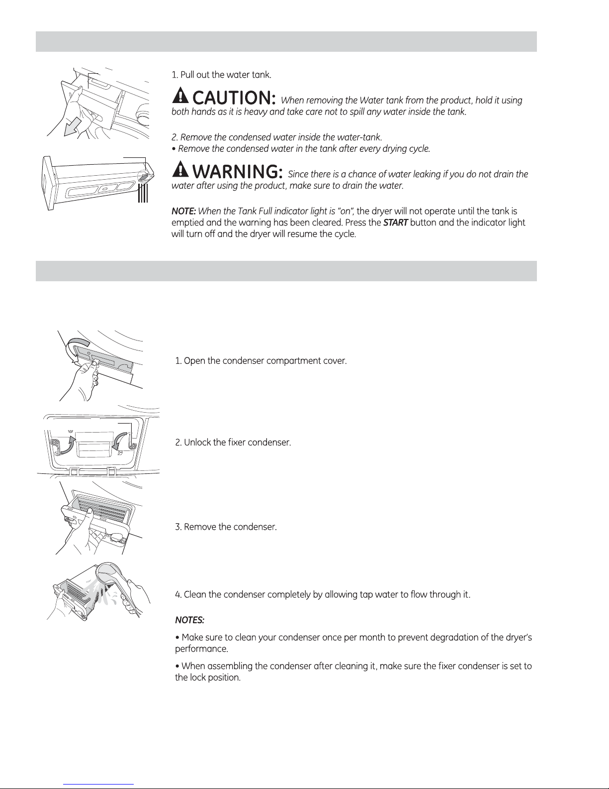
Cleaning the Condenser...........................................................................................................................................10
Component Locator Views......................................................................................................................................23
Condensate Pump.......................................................................................................................................................35
Condensation ................................................................................................................................................................22
Connecting the Drain Hose.....................................................................................................................................12
Control Board.................................................................................................................................................................29
Control Board Connections.....................................................................................................................................27
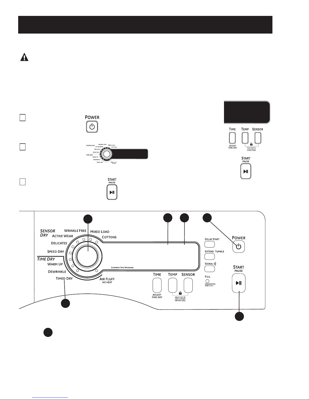
Control Features............................................................................................................................................................. 6
Control Panel ................................................................................................................................................................28
Cycle Options................................................................................................................................................................... 9
Door Switch ....................................................................................................................................................................31
Drum and Bearing.......................................................................................................................................................41
Drum Belt.........................................................................................................................................................................39
Drum Lamp Assembly...............................................................................................................................................31
Drum Rollers...................................................................................................................................................................34
Drum Support Assembly..........................................................................................................................................32
Dryer Components......................................................................................................................................................28
Emptying the Water Tank........................................................................................................................................10
Error Codes .....................................................................................................................................................................47
Float Switch....................................................................................................................................................................36
Front Panel......................................................................................................................................................................30
Heater Assembly..........................................................................................................................................................37
Inlet Thermistor.............................................................................................................................................................38
Introduction...................................................................................................................................................................... 4
Location of the Dryer.................................................................................................................................................11
Manual Reset Thermostat .......................................................................................................................................38
Motor Assembly ...........................................................................................................................................................43
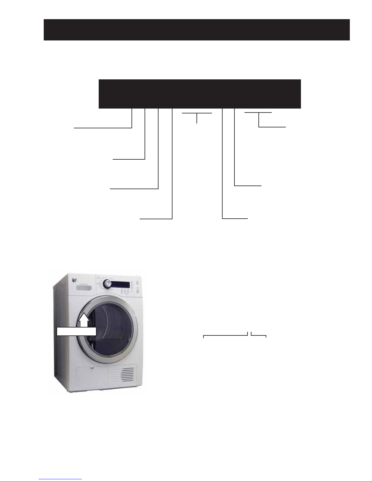
Nomenclature ................................................................................................................................................................. 5
Operation Overview....................................................................................................................................................19
Outlet Thermistor.........................................................................................................................................................32
Rear Blower Wheel......................................................................................................................................................39
Rear Drum Seal Assembly.......................................................................................................................................42
Reversing the Door Swing .......................................................................................................................................13
Schematics and Wiring Diagrams.......................................................................................................................48
Service Test Mode........................................................................................................................................................45
Stacking Instructions .................................................................................................................................................16
Top Cover.........................................................................................................................................................................28
Touch Sensors ..............................................................................................................................................................34
Troubleshooting ...........................................................................................................................................................45
Warranty .........................................................................................................................................................................49

– 4 –
The new GE 24-in. ventless condenser dryer has the following features:
• Nine heat cycles - 6 Sensor Dry cycles and 3 Time Dry cycles.
• Large 4.0-cubic foot 304 stainless steel dryer drum.
• LED Drum Lamp
• Built-in service test mode. Specific dryer components can be operated. Error codes are recorded and
accessible on the control panel display.
• Thermistor - Thermistors are more sensitive to temperature changes and can relay the information faster
than thermostats. The dryer utilizes a thermistor to monitor air temperature leaving the drum. The sensor
works together with the variable heater and the blower to provide consistent, even heat.
• Moisture Sensor - The moisture sensor allows the control to monitor the fabric for moisture content and
end the cycle at the desired moisture level.
• Flush Door Handle
• Reversible Door
• UV Stabilizers - The control panel has UV stabilizers to prevent yellowing when exposed to sunlight.
• The GE 24-in. condenser dryer, models DCCH480EK and DCCH485EK, can be installed on top of GE 24-in.
HA washers, models WCVH4800K and WCVH4815K. Use stacking kit GE24STACK.
Introduction

– 5 –
Nomenclature
The nomenclature tag is located on
the front panel inside the door.
Note: The technical sheet is located
inside the control panel.
Product
C = Condenser Dryer
D C C H 4 8 5 E K W W
Brand
D = General Electric
Configuration
C = Front Load
Key Feature
Color
WW = White
BB = Black
Model Year Designator
K = 2010
Fuel
E = Electric
Series
Nomenclature
Serial Number
The first two characters of the serial number
identify the month and year of manufacture.
Example: FV123456S = March, 2011
F- MAR
G - APR
H - MAY
L - JUN
M - JUL
R - AUG
S - SEP
T - OCT
V - NOV
Z - DEC
A - JAN
B - FEB
2011 - V
2010 - T
2009 - S
2008 - R
2007 - M
2006 - L
2005 - H
2004 - G
2003 - F
2002 - D
2001 - A
2000 - Z
The letter designating
the year repeats every
12 years.
Example:
V - 2011
V - 1999
V - 1987

– 6 –
Control Features
(Continued Next Page)
WARNING! To reduce the risk of fire, electric shock, or injury to persons, read the
IMPORTANT SAFETY INSTRUCTIONS before operating this appliance.
Throughout this manual, features and appearance may vary from your model.
Quick Start
If the screen is dark, press the POWER button to “wake up”
the display.
Press the
POWER
button.
Select a cycle by turning the
Cycle Knob.
If you selected a SENSOR DRY cycle—
just press the START/PAUSE button.
If you selected a TIME DRY
cycle—select your heat setting
and the amount of time you
want your items to dry by
pressing the TIME button until
the desired time appears in
the display. Then press the
START/PAUSE button.
3
2
1
Power
Press to “wake up” the display. If the display is active, press to turn the dryer off.
NOTE: Pressing POWER does not disconnect the appliance from the power supply.
1
1
2
3
4 5
6

– 7 – (Continued Next Page)
2Dry Cycles
The dry cycle controls the cycle time for the drying process. The chart below will help you match
the dry setting with the loads.
Sensor Cycles
COTTONS For cottons and most linens.
MIXED LOAD For loads consisting of cottons and poly blends.
WRINKLE FREE For wrinkle-free/easy care and permanent press items.
ACTIVE WEAR Clothing worn for active sports exercise and some casual wear. Fabrics include new
technology finishes and stretch fibers such as spandex.
DELICATES For lingerie and special-care fabrics.
SPEED DRY For small loads that are needed in a hurry, such as sports or school uniforms. Can also be
used if the previous cycle left some items damp, such as collars or waistbands.
Time Dry Cycles
WARM UP Provides 10 minutes of warming time to warm up clothes.
DEWRINKLE For removing wrinkles from items that are dry or slightly damp. This cycle is not
recommended for delicate fabrics.
AIR FLUFF Use this feature to tumble items without heat.
Timed Dry
Use to set your own dry time. TIMED DRYis also recommended for small loads.
To use TIMED DRY:
1. Turn dry cycle dial to TIMED DRY.
2. Select the drying time by pressing the TIME button. You can increase the time in 10-minute
increments up to 1 hour and 20 minutes.
3. Select the DRY TEMP.
4. Close the door.
5. Press START/PAUSE.
Sensor Dry Level
The sensor continuously monitors the amount of moisture in the load. When the moisture in your
clothes reaches your selected dry level, the dryer will stop.
EXTRA DRY Use for heavy-duty fabrics or items that should be very dry, such as towels.
MORE DRY Use for heavy or mixed type of fabrics.
DRY Use for normal dryness level suitable for most loads. This is the preferred cycle
for energy saving.
LESS DRY Use for lighter fabric (ideal for ironing).
DAMP For leaving items partially damp.
NOTE: The Sensor Dry Levels can only be selected in a Sensor Dry Cycle.
3
4

– 8 – (Continued Next Page)
Dry Temp
You can change the temperature of your dry cycle.
ANTI-BACTERIAL This option may only be used with COTTONS or MIXED LOAD cycles. This option reduces
certain types of bacteria. The anti-bacterial process occurs when high heat is used
during a portion of this drying cycle.
NOTE: Do not use this cycle on delicate fabrics.
HIGH For regular to heavy cottons.
MEDIUM For synthetics, blends and items labeled permanent press.
LOW For delicates, synthetics and items labeled Tumble Dry Low.
EXTRA LOW For lingerie and special-care fabrics.
START/PAUSE
Press to start a dry cycle. If the dryer is running, press it once and it will pause the dryer.
Press it again to restart the dry cycle.
“CLEAN LINT FILTER” (message)
This message stays on until the START button is pressed. This message is only a reminder.
5
6

– 9 –
Cycle Options
(Continued Next Page)
Extend Tumble
Minimizes wrinkles by adding
approximately 20 minutes of constant
no-heat tumbling followed by 70 minutes
of intermittent no-heat tumbling after
clothes are dry. The dryeris in EXTENDED
TUMBLEwhen the ESTIMATED CYCLE TIME
display is illuminated in a circular pattern.
The light in the button will light up when
EXTEND TUMBLE is on.
NOTE: It is normal for the drum to pause
for short periods of time during EXTEND
TUMBLE.
Delay Start
Use to delay the start of your dryer.
1. Choose your dry cycle and any options.
2. Press the DELAY START button. You
can change the delay time in 1-hour
increments (up to 18 hours) each time
you press the DELAY START button. Stop
pressing the button when your desired
time is displayed.
3. Press the START/PAUSE button to start
the countdown.
The countdown time will be shown in the
ESTIMATED TIME REMAININGdisplay.
NOTES:
If the door is opened while the dryer is in
DELAY, the countdown time will continue
to count down the delay time. If the door
is not closed and the countdown time
expires, the cycle will not start until the
door is closed and the START/PAUSE
button is pressed.
You can delay the start of a dryer cycle
up to 18 hours.
The light in the button will light up when
DELAY START is on.
Lock
You can lock the controls to prevent any
selections from being made. Or you can
lock or unlock the controls after you have
started a cycle.
Children cannot accidentally start
the dryer by touching pads with
this option selected.
To lock the dryer, press and hold
the TEMP and SENSOR buttons together
for 3 seconds.
To unlock the dryer controls, press
and hold the TEMP and SENSOR buttons
together for 3 seconds. A sound will
indicate the lock/unlock status.
The control lock icon on the display will
light up when it is on.
NOTE: The POWER button can still be used
when the machine is locked.
Signal
When the light is “on,” the dryer will beep
at the end of the cycle and every time
you press a button on the control panel.
To turn the signal off, press the SIGNAL
button and the light will go off.
Tank Full Indicator
When the light is “on,” you must empty the
tank before continuing use of the dryer.
Remove the tank and empty the water.
Replace the tank and clear the warning light.
(See page 11)
NOTE: The dryer will not operate until the
tank is emptied and the warning has been
cleared.

– 10 –
Emptying the Water Tank
Cleaning the Condenser
Water-Tank
Drain hole
Important: The condenser should be cleaned once a month.
Fixer Condenser

– 11 –
Location of the Dryer
BATHROOM OR BEDROOM
INSTALLATION
•The installation must conform with local codes or,
in the absence of local codes, with the NATIONAL
ELECTRICAL CODE, ANSI/NFPA NO. 70 (for electric
dryers) or NATIONAL FUEL GAS CODE, ANSI Z223
(for gas dryers).
MOBILE OR MANUFACTURED HOME
INSTALLATION
•The installation must conform to the
MANUFACTURED HOME CONSTRUCTION & SAFETY
STANDARD, TITLE 24, PART 32–80 or, when such
standard is not applicable, with AMERICAN
NATIONAL STANDARD FOR MOBILE HOME,
NO. 501B.
•Provide an opening with a free area of at least
25 sq. in. for introduction of outside air into the
dryer room.
UNDERCOUNTER INSTALLATION
If an undercounter installation is desired:
•No special dryer installation kit is required.
•If the dryer is installed alone, a minimum of
60 square inches of open area is required.
If a washer and dryer are installed together,
a minimum of 120 square inches of open area
is required.
Washer and Dryer installed together
120
square
inches
min.
open
area
Countertop and side cabinets
Dryer installed alone
60
square
inches
min.
open
area
Countertop and side cabinets

– 12 –
Connecting the Drain Hose
A
A
B
Drain hose
Hose guid e
90 cm
Cable Ti e

– 13 –
Reversing the Door Swing
Important Notes:
• Read the instructions all the way thru before
starting.
• Handle parts carefully to avoid scratching paint.
• Provide a non-scratching work surface for the
doors.
• Set screws down by their related parts to avoid
using them in the wrong places.
• All screws must be hand-tightened.
• Normal completion time to reverse the door
swing is 20–30 minutes.
Important: Once you begin, do not move the
cabinet until door-swing reversal is completed.
These instructions are for changing the hinges from
the right side to the left side―if you ever want to
switch them back to the right side, follow these
same instructions and reverse all references to the
left and right.
Hardware Used
Mounting Screw
Hinge Bracket Anchoring
Screws
Door and Latch Screws
Tools Needed
Phillips-head Screwdriver
(Continued Next Page)

– 14 – (Continued Next Page)
To reverse the door swing:
1. Unplug the dryer from its electrical outlet.
2. Remove the hinge bracket anchoring screws.
3. Slide door and hinge assembly upward, and
then remove the assembly from the dryer front
panel.
4. Remove 16 door screws and male end of latch
from the inner side of the door.
5. Remove the inner face.
6. Lift and rotate the window assembly 180° and
place it back into the assembly. Also rotate the
inner face 180 degrees and place it into the
assembly.
7. Replace a door screw in the center of the side
opposite the hinge. Put the male end of the latch
into place and fasten with two door screws.

– 15 –
8. Replace all door screws that were removed.
9. Remove the female end of the latch from the
front panel of the dryer, rotate 180 degrees, and
place it into the assembly on the opposite side.
10. Move the mounting screw to the upper screw
hole position on the hinge so that the door can
be set on the cabinet during final installation.
11. Fasten the hinge back on at the top and bottom
with the hinge mounting screws.

– 16 – (Continued Next Page)
The GE dryer is designed to allow placement
(stacking) on top of certain GE front-loading
washers. Washer models that currently qualify are:
• WCVH4800K
• WCVH4815K
Note: If you are planning to stack the washer and
dryer, order Stacking Kit number GE24STACK to be
used for this dryer. Kit sold separately.
• IMPORTANT – Save these instructions for local
electrical inspector’s use.
• IMPORTANT – Observe all governing codes and
ordinances.
• Note to Installer – Be sure to leave these
instructions with the Consumer.
• Stacking installations may require a power cord
up to six feet in length.
WARNING!
• Make sure the dryer is unplugged.
• More than 2 people are recommended to safely
lift the dryer into position.
• Avoid damage to the existing utility services.
• DO NOT place the washer on top of the dryer.
Location Requirements
When installed in a location other than an alcove
or closet, the minimal clearances to combustible
surfaces and for air opening are: 0 inches on both
sides, and 3 inches front and rear. Consideration
must be given to provide adequate clearance for
installation and service.
Note: Your dryer is approved for installation in an
alcove or a closet, as stated on a label on the dryer
back.
When installed in an alcove or closet:
• Minimum clearance between dryer cabinet
and adjacent walls or other surfaces is 0 inches
either side, and 3 inches front and rear.
• Minimum vertical space from floor to overhead
shelves, cabinets, ceilings, etc., is 67.7 inches.
• Closet doors must be louvered or otherwise
ventilated and have at least 60 square inches
of open area equally distributed. If the closet
contains both a washer and a dryer, doors must
contain a minimum of 120 square inches of
open area equally distributed.
Stacking Instructions

– 17 – (Continued Next Page)
Tools Needed
Phillips-head Screwdriver
Kit Contents (GE Kit #GE24STACK)
Screws (4)
Rubber
pads (4)
Bracket-
stack (R)
Bracket-
stack (L)
Level
Gloves
Installation Preparation
Remove the packaging.
Flatten the product carton to use as a pad to lay the
dryer down on its side. Continue using the carton to
protect the finished floor in front of the installation
location.
1. Carefully lay the dryer on its side. Use the
packing material so you don’t scratch the finish
on the dryer.
2. Remove the dryer leveling legs.
Unscrew and remove
all 4 leveling legs
3. Locate the 4 rubber pads in the parts package.
Insert rubber pads into the leveling leg holes.
4. Set the dryer upright.
Installing the Stack Bracket Kit

– 18 –
5. Remove washer top cap screw from the rear
left. Align left bracket holes with top cap
screw hole on rear left of the unit and replace
screw. Note: Leave screws loose so dryer hole
alignment will be easier.
6. Drive next screw thru the bracket into the rear of
the washer.
7. Repeat the above steps with the right side.
8. Lift the dryer on top of the washer. Protect the
washer control panel with cardboard or other
protection. Be sure to lift the dryer high enough
to clear the washer control panel.
WARNING – Potential Personal Injury. More than
2 people are recommended to lift the dryer into
position because of its weight and size. Failure to do
so could result in personal injury or death.
9. Align the holes in the bracket with the holes
in the back of the dryer. Using a Phillips
screwdriver, attach the 2 #8 x 1/2-in. tapping
screws.
10. Tighten the dryer bracket screws and then
tighten all stacking kit screws.
11. Refer to the washer Installation Instructions to
complete the washer installation.
12. Refer to the dryer Installation Instructions to
complete the dryer installation.
13. Carefully slide or walk the stacked washer and
dryer into place. Use felt pads or other sliding
devices to assist moving and to protect flooring.
WARNING – Potential Personal Injury. Do not push
on the dryer once installed to top of the washer.
Pushing on the dryer may result in pinched fingers.
Place
hands
here
Place
hands
here

– 19 –
Operation Overview
Characteristics of a Condenser Dryer
A condenser clothes dryer is a machine that looks just like a conventional tumble clothes dryer, but does not
require an external vent. For the consumer, operation of both types of dryers is essentially the same - the
difference is in the internal design.
In a vented clothes dryer, air is drawn from the surrounding area (i.e. the laundry room), then heated and
blown thru the clothes as the drum tumbles them about. This hot air evaporates some of the water in the
damp fabrics, and the resultant moisture-laden air is then exhausted thru a vent duct to the outside.
In a condenser dryer, there are two separate "loops". The inside "loop" of air is sealed from the outside
environment - air from within the drum is heated, and then blown thru the tumbling clothes. The moisture-
laden air is passed thru a “condenser”, where the water re-condenses.
Some condenser dryer models are air-cooled. They use the ambient room air as a heat sink by blowing
it across the outside of the condenser. These dryers tend to heat the indoor air in one's laundry room
significantly. Note however that ONLY heat is released – all MOISTURE is contained within the unit. The
condensed water can be either pumped away to a drain line (e.g. into a standpipe shared with the clothes
washer) or stored in a container within the dryer to be emptied later.
The typical dryer cycle progresses as follows:
1. A cycle is selected and the START/PAUSE button is pressed.
2. The motor is activated. The drum motor rotates the drum at a speed of approximately 50 rpm
(revolutions per minute).
3. The heater elements are activated. The elements cycle on and off to achieve the desired temperature
throughout the heating portion of the cycle.
4. If sensor drying is selected, the heater elements are activated. The elements cycle on and off until the
load has achieved the desired dryness level.
5. If timed drying is selected, the heater elements are activated and cycle on and off for the selected time
at the selected temperature.
6. The heater coils discontinue operation after the dryness level or elapsed time has been achieved.
7. The motor continues operating until the clothes temperature drops below a specified temperature (cool
down).
9. The display turns off.
Temperature Control
Overall heater temperature is regulated by means of an inlet thermistor, located above the heater assembly,
and an outlet thermistor, located below the lint filter.
Two safety thermostats are located on top of the heater assembly. The auto reset thermostat opens at 212°F
(100°C) and closes at 176°F (80°C). If the auto reset thermostat reaches a temperature beyond its maximum
temperature rating, it will cut power to the heating elements.
The manual reset thermostat opens at 293°F (145°C) and can only be closed manually. If the manual reset
thermostat reaches a temperature beyond its maximum temperature rating, it will cut power to the heating
elements and the control board, thereby terminating dryer operation.

– 20 –
AIR FLOW AND SEALS
Proper air flow thru the dryer is essential for normal
operation of the temperature control and safety
systems. There are two separate air flows in the dryer:
the enclosed process air and the cooling (ambient) air.
The ambient air is drawn thru louvers at the front of the
unit (1) by the front blower wheel (2) and then flows over
the condenser (3) cooling the process air. The ambient
air then exits the dryer thru louvers in the back of the
dryer.
The process air is pulled thru the condenser (4) by the
rear blower wheel (5) and travels up the rear channel
(6) to the electric heater (7) where it is warmed up and
drawn into the drum (8) thru a diffuser. The heated
process air dries the clothes and then flows thru the lint
filter (9) and into the condenser (4), where it is cooled
down and the moisture condensed out.
The same dry air is then reheated, where it is again
blown thru the drum and clothes, and the cycle begins again (this is a more-or-less continuous process).
If the ambient air flow is restricted in anyway, it will decrease the performance of the condenser and
significantly increase drying times.
Proper air flow thru the dryer is essential for normal operation of the temperature control and safety
systems. The back cover must be in place for proper airflow.
The temperature of the process air rises by passing thru the electric heaters. This heated air enters thru holes
in the back of the drum and dries the clothes load. The air containing moisture is pulled thru the lint filter,
where lint is screened by the filter, and enters the condenser. The moisture is condensed and the warm air
cycles thru the drum again.
Any air leaks in the enclosed system will result in improper temperatures.
Airflow
1
3
4
5
6
7
8
9
2
Other manuals for DCCH480EK
2
This manual suits for next models
1
Table of contents
Other GE Dryer manuals