manuals.online logo
Brands
  1. Home
  2. •
  3. Brands
  4. •
  5. GE
  6. •
  7. Dryer
  8. •
  9. GE DLSR483GG4WW User manual

GE DLSR483GG4WW User manual

GasDryer
5O
IIf you have any questions, carl 1-800-GECARES (US) or 1-800-361-3400 (Canada)
or Visit our Web site at: www. GEAppliances.com
BEFOREYOU BEGIN
Read these instructions completely and carefully.
IMPORTANT -Savethese
instructions for local inspector's use.
IMPORTANT =Observeall
governing codes and ordinances.
Note to Installer - Be sure to leave these instructions with
the customer
Note to Customer - Keep these instructions with your Use
and Care Book for future reference.
This dryer must be exhausted to the outdoors.
Before the old dryer is removed from service or discarded,
remove the dryer door.
Service Information and the wiring diagram are located in
the control console.
Service of this dryer must be performed by a qualified
installer,service agency, or the gas supplier.
Do not allow children on or in the appliance. Close
supervision of children is necessary when the appliance is
used near children.
TOOLS YOU WiLL NEED
10"ADJUSTABLEWRENCHES(2)
SLIPJOINTPLIERS
FLATBLADESCREWDRIVER
8"PIPEWRENCH %
LEVEL
FORYOUR SAFETY:
WARNING
•Use only rigid metal or flexible metal 4-in. diameter
ducrwork for exhausting to the outdoors. Never use
plastic or other combustible easy-to-puncture ductwork.
•This appliance must be properly grounded and installed
as described in these instructions.
•Do not install or store appliance in an area where it
will be exposed to water and/or weather.
• The National Fuel Gas Code restricts installations of
gas appliances in garages. They must be 18 in. off the
ground and protected by a barrier from vehicles.
•Install the dryer where the temperature is above 50°F
for satisfactory operation of the dryer control system.
licensed by the state.
MATERIALSYOU WiLL NEED
%
4"DIA,METALELBOW
PIPECOMPOUND
FLEXIBLEGASLINECONNECTOR
4"DIA,METALDUCT
(RECOMMENDED)
4"DIA.FLEXIBLEMETALDUCT
(IFNEEDED)
GLOVES
DUCT SOAPSOLUTION
CLAMPS(2) FORLEAKDETECTION
EXHAUSTHOOD
SAFETYGLASSES DUCTTAPE
Step 1
Step 2
Step 3
Step 4
Step 5
Step 6
Step 7
Verify Your Gas Installation (see section 2).
Prepare the Area and Exhaust for Installation of
New Dryer (see section 1).
Check and Insure the Existing External Exhaust is
Clean (see section 1) and Meets Attached Installation
Specifications.(see section 6)
Remove the Foam Shipping Pads (see section 1).
Move the Dryer to tile Desired Location.
Level Your Dryer (see section 8).
Connect tile Gas Supply (see section 3) and check
for leaks (see section 4).
Step 8 Connect the External Exhaust (see section 7).
Step 9 Connect the Power Supply (see section 5).
Step 10 Check the Operation of the Power Supply, Gas
Connections, and Venting.
Step 11 Place the Owners Manual and the Installation
Instructions in a Location Where They _rill Be
Noticed By the Owner.
For Alcove or Closet Installation see section 9.
For Bathroom or Bedroom Installation see section 10.
For Mobile or Manufactured Home see section 11.
Installation instructions
Minimum Clearance Other Than Alcove or Closet Installation
Minimum clearance to combustible surfaces and fox'air opening are: 0 in. clearance both skies and 1in. rear. Consideratkm
must be given to provkte adequate clearance for proper operation and service.
[] PREPARING FOR iNSTALLATiON
OF NEW DRYER
EXTERNAL
DUCT
OPENING
CSA(AGA)APPROVED
NEWFLEXIBLEGAS
LINECONNECTOR
GAS
INLET
PIPE
TAPE
4"METALDUCT
DUCT
TAPE
TIP: Install your dryer before installing your washer.
This will allow better access when installing dryer exhaust.
DiSCONNECTiNG GAS
TURNGAS . .__
SHUT-OFF
VALVETOTHE
OFFPOSITION.
DISCONNECTANDDISCARDOLD
FLEXIBLEGASCONNECTOR
ANDOLDDUCTINGMATERIAL.
Z_ WARNING - NEVERREUSE OLD
FLEXIBLE CONNECTORS.
The use of old flexible connectors can cause leaks and
personal injury. Always use new flexible connectors when
installing gas appliances.
REMOVING LiNT FROM WALL
EXHAUST OPENING
WALL
/
INTERNALDUCT CHECKTHATEXHAUST
OPENING OPENS
ANDCLOSESFREELY,
2
TILTTHEDRYERSIDEWAYS
ANDREMOVETHEFOAM
SHIPPINGPADSBY
PULLINGATTHESIDES
ANDBREAKINGTHEM
AWAYFROMTHEDRYER
LEGS,BESURETO
REMOVEALLOFTHE
FOAMPIECESAROUND
THELEGS.
[] GAS REQUIREMENTS
WARNING
. Installation must conform to local codes and ordinances,
or in their absence, the NATIONAL FUEL GAS CODE,
ANSI Z223
. This gas dryer is equipped with a Valve & Burner Assem-
bly for use only with natural gas. Using conversion kit
WE25X0217, your local service organization can convert
this dryer fox'use with propane (LP) gas. ALL CONVER-
SIONS MUST BE MADE BY PROPERLY TRAINED
AND QUALIFIED PERSONNEL AND IN AC-
CORDANCE WITH LOCAL CODES AND ORDI-
NANCE REQUIREMENTS.
. The dryer must be disconnected fl'om the gas supply
piping system during any pressure testing of that system
at a test pressure in excess of 0.5 PSI (3.4 KPa).
. The dryer must be isolated fl'om the gas supply piping
system by closing the equipment shut-off valve during
any pressure testing of the gas supply piping of test
pressure equal to or less than 05 PSI (3.4KPa).
DRYER GAS SUPPLY CONNECTION
A..............1_ J J
24/8" 3/8"NPTMALETHREADGASSUPPLY
NOTE:Addtoverticaldimension
thedistancebetweencabinet
bottomtofloor.
GAS SUPPLY
A 1/8-in. National Pipe Taper thread plugged tapping, ac-
cessible for test gauge connection, must be installed imme-
diately upstream of the gas supply connection to the dryer.
Contact your local gas utility should you have questions on
the installation of the plugged tapping.
Supply line is to be 1/2-in. rigid pipe and equipped with an
accessible shut-offwithin 6 ft. of, and in the same room
with, the dryer.
Use pipe thread sealer compound appropriate for natural
or LP gas or use Teflon tape
The flexible gas connector, when used, must not exceed 3 feet.
Connect flexible metal connector to dryer and gas supply.
Open shut-off valve.
Installation
[] RECONNECTING GAS
NEWMETAL
FLEXIBLEGAS
LINECONNECTOR
ADAPTER
ITEMSNOTSUPPLIED
ELBOW 3/8"NPT
1/8"NPTPIPE
PLUGFORGAS
INLETPRESSURE
SHUTOFF
VALVE
X
__PIPE SIZE
ATLEAST1/2"
APPLYPIPECOMPOUND
TOTHEADAPTERAND
DRYERGASINLET.
\
TIGHTENTHEFLEXIBLE
GASLINEUSINGTWO
ADJUSTABLEWRENCHES.
Instructions
APPLYPIPECOMPOUND
TOALLMALETHREADS.
TIGHTENALLCONNECTIONS
USINGTWOADJUSTABLEWRENCHES.
DONOTOVERTORQUEGASCONNECTIONS!
[] LEAK TEST
[ ,d_WARNING - NEVER USE AN OPEN
FLAME TO TEST FOR GAS LEAKS.
OPEN
GASVALVE.
Check all connections fbr leaks with soapy solution oi" equivalent.
Apply soap solution. Leak test solution must not contain
ammonia which could cause damage to the brass fittings. If
leaks are found, close valve, retighten the joint, and repeat the
soap test.
Installation
[] ELECTRICAL CONNECTION
iNFORMATiON
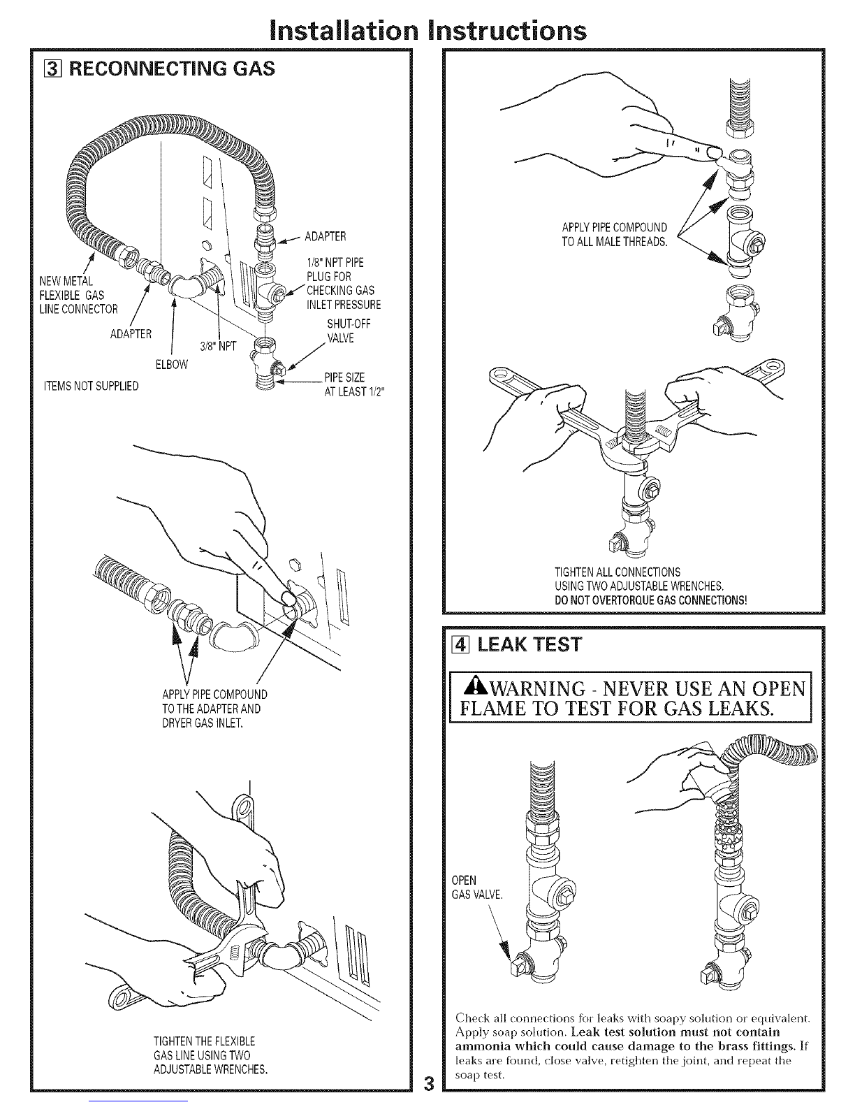
WARNING- TO REDUCE THE RISK OF
FIRE, ELECTRICAL SHOCK, AND PERSONAL
INJURY:
DO NOT USE AN EXTENSION CORD OR AN
ADAPTER PLUG WITH THIS APPLIANCE.
Dryer must be electrically grounded in accordance with
local codes and ordinances, or in the absence of local
codes, in accordance with the NATIONAL ELECTRI-
CAL CODE, ANSI/NFPA NO. 70.
ELECTRICAL REQUIREMENTS
This appliance must be supplied with 120V, 60Hz, and connected
to a properly grounded branch circuit, protected by a 15- or 20-
amp circuit breaker or time-delay fuse. If electrical supply provid-
ed does not meet the above specifications, it is reconnnended that
a licensed electrician install an apt)roved outlet.
_WARNING - THIS DRYER IS EQUIPPED
A THREE-PRONG (GROUNDING) PLUG FOR
YOUR PROTECTION AGAINST SHOCK
HAZARD AND SHOULD BE PLUGGED
DIRECTLY INTO A PROPERLY GROUNDED
THREE-PRONG RECEPTACLE. DO NOT CUT
OR REMOVE THE GROUNDING PRONG
FROM THIS PLUG.
ENSURE PROPER GROUND EXISTS BEFORE USE.
?-
IFLOCALCODESPERMIT,
ANEXTERNALGROUNDWIRE
(NOTPROVIDED},WHICHMEETS
LOCALCODES,MAYBEADDED
BYATTACHINGTOTHEGREEN
GROUNDSCREWONTHEREAR
OFTHEDRYER,ANDTOA GROUNDED
METALCOLDWATERPIPEOROTHER
ESTABLISHEDGROUND.
instructions
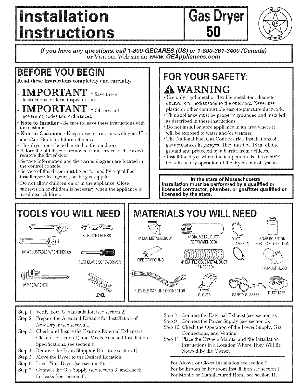
[] EXHAUST iNFORMATiON
A
_WARNING - USE ONLY METAL 4-IN. DUCT.
DO NOT USE DUCT LONGER THAN SPECIFIED
IN THE EXHAUST LENGTH TABLE.
Exhaust longer than specified will:
• Increase the drying times and the energy cost.
" Reduce the dryer life.
• Accunmlate lint, creating a potential fire hazard.
The correct exhaust installation is your responsibility.
Problems due to incorrect installation a,,e not covered
by the warranty.
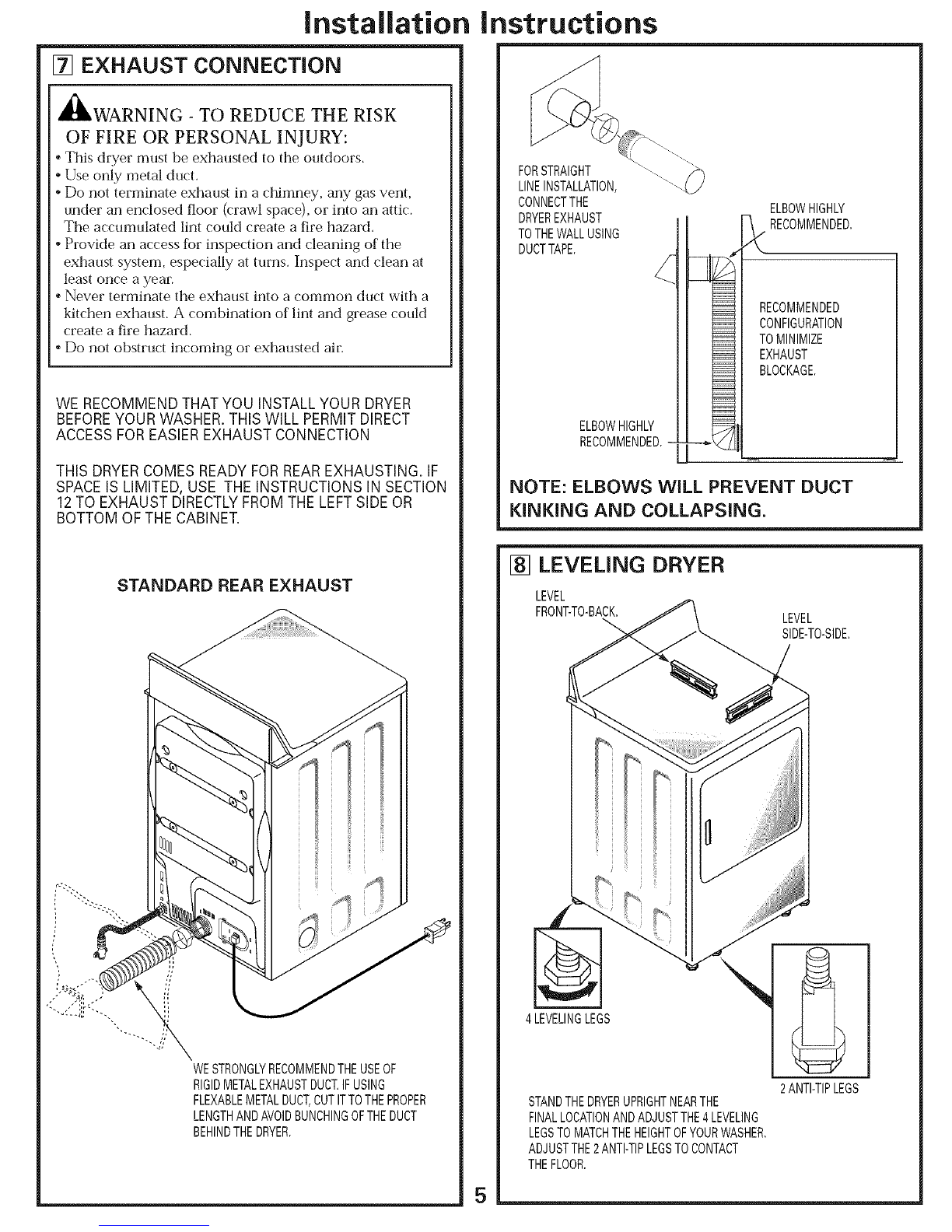
The MAXIMUM ALLOWABLE length of the exhaust system
depends upon the type of duct, number of turns, the type of
exhaust hood (wall cap), and all conditions noted below-. Both
rigid and flexible metal duct are shown in the table below:
No. of 90 °
Elbows
0
1
2
3
4
5
EXHAUST LENGTH
RECOMMENDED MAXIMUM LENGTH
Exhaust HoodTypes
Recommended
Rigid Flexible
Metal Metal
150 Feet 55 Feet
135 Feet 52 Feet
125 Feet 49 Feet
115 Feet 46 Feet
105 Feet 43 Feet
95 Feet 40 Feet
Use onlyfor short
run installations
4" DIA.
Rigid Flexible
Metal Metal
125 Feet 45 Feet
115 Feet 42 Feet
105 Feet 39 Feet
95 Feet 36 Feet
85 Feet 33 Feet
75 Feet 30 Feet
4
If using flexible metal duct, please refer to page 6.
EXHAUST SYSTEM CHECK LiST
HOOD OR WALL CAP
•Terminate in a manner to prevent back drafts or entry of birds or
other wildlife.
•Termination should present minimal resistance to the exhaust air flow
and should require little or no maintenance to prevent clogging.
•Never install a screen in or over the exhaust duct.
•Wall caps must be installed at least 12in. above ground level or any other
obstruction with the opening pointed down.
•If roof vents or louvered plenmns are used, they must be equivalent to a
4-in. dampened wall cap in regard to resistance to air flow, prevention of
back drafts, and maintenance required to prevent clogging.
SEPARATION OF TURNS
Fox'best performance, separate all turns by at least 4 fL of straight duct,
including distance between last turn and dampened wall cap.
TURNS OTHER THAN 90°
o
•One turn of 45 or less may be ignored.
o( o
•Two 45 turns should be treated as one J0 turn.
o
•Each turn over 45oshould be treated as one ,)0 turn.
SEALING OF JOINTS
"All joints should be tight to avoid leaks. The male end of each section of
duct must point away fi'om the dryer.
•Do not assemble the ductwork with fasteners that extend into the duct.
They will serve as a collection point for lint.
•Duct joints should be made air-and moisture-tight by wrapping the
overlapped joints with duct tape.
•Horizontal runs should slope down towm'ds outdoors 1/2 inch pet"fbot,
INSULATION
•Duct work that runs through an unheated area or is near air conditioning
should be insulated to reduce condensation and lint build up_
Installation
[] EXHAUST CONNECTION
_WARNING - TO REDUCE THE RISK
OF FIRE OR PERSONAL INJURY:
*This dryer must be exhausted to the outdoors.
*Use only metal duct.
*Do not terminate exhaust in a chimney, any gas vent,
under an enclosed floor (crawl space), or into an attic.
The accumulated lint could create a fire hazard.
*Provide an access for inspection and cleaning of the
exhaust system, especially at turns. Inspect and clean at
least once a year.
* Never terminate the exhaust into a common duct with a
kitchen exhaust. A combination of lint and grease could
create a fire hazard.
* Do not obstruct incoming or exhausted air.
WE RECOMMEND THAT YOU INSTALL YOUR DRYER
BEFOREYOUR WASHER. THIS WILL PERMIT DIRECT
ACCESS FOR EASIEREXHAUST CONNECTION
THIS DRYERCOMES READY FORREAREXHAUSTING. IF
SPACEIS LIMITED, USE THE INSTRUCTIONS IN SECTION
12 TO EXHAUST DIRECTLYFROM THE LEFTSIDE OR
BOTTOM OF THE CABINET.
STANDARD REAR EXHAUST
WESTRONGLYRECOMMENDTHEUSEOF
RIGIDMETALEXHAUSTDUCT.IFUSING
FLEXABLEMETALDUCT,CUTITTOTHEPROPER
LENGTHANDAVOIDBUNCHINGOFTHEDUCT
BEHINDTHEDRYER.
Instructions
FORSTRAIGHT
LINEINSTALLATION,
CONNECTTHE ELBOWHIGHLY
DRYEREXHAUST -_ RECOMMENDED.
TOTHEWALLUSING
DUCTTAPE.
ELBOWHIGHLY
RECOMMENDED,-
RECOMMENDED
CONFIGURATION
TOMINIMIZE
EXHAUST
BLOCKAGE,
NOTE: ELBOWS WILL PREVENT DUCT
KINKING AND COLLAPSING.
[] LEVELING DRYER
LEVEL
FRONT-TO-BACK.
_. LEVEL
SIDE-T0-SIDE
4LEVELINGLEGS
STANDTHEDRYERUPRIGHTNEARTHE
FINALLOCATIONANDADJUSTTHE4LEVELING
LEGSTOMATCHTHEHEIGHTOFYOURWASHER,
ADJUSTTHE2ANTI-TIPLEGSTOCONTACT
THEFLOOR.
2ANTI-TIPLEGS
Installation instructions
USING FLEXIBLE METAL DUCTS
If rigid all-metal duct cannot be used, then flexible all-metal
venting can be used, but it will reduce the maximum
recommended duct length. In special installations when it is
impossible to make connection with the above recommendations,
then UL-listed clothes dryer transition duct may be used as
transition venting between the dryer and wall connection only. The
use of this ducting will affect dry time.
If flexible transition duct is necessary, the following directions Ernst
be followed.
•Use the Shortest Length Possible.
•Stretch the Duct to Its Maxinmm Length.
• Do Not (;rush or Collapse.
° Never Use Transition Duct Inside the Wall or
Inside the DryeI:
° Avoid Resting the Duct on Sharp Objects.
° Venting Must Conform to Local Building Codes.
ELBOWHIGHLY
RECOMMENDED
ELBOWSHIGHLY
RECOMENDED -_
)(
DONOTUSE
EXCESSIVE ,DONOT
_. CRUSH
FLEXIBLE
_I EXHAUST
_ AGAINST
--WAL,%
[] ALCOVE OR CLOSET INSTALLATION
• If your dryer is approved for installation in an alcove or
closet, it will be stated on a label on the dryer back.
° The dryer MUST be vented to the outdoors. See the
EXHAUST INFORMATION section.
° Minimum clearance between dryer cabinet and adjacent
walls or other surfaces is:
0 in. either side
3 in. front and rear
° Minimum vertical space from floor to overhead cabinets,
ceiling, etc. is ,52 in.
° Closet doors must be louvered or otherwise ventilated and
must contain a minimum of 60 sq. in. of open area equally
distributed. If the closet contains both a washer and a
dryer, doors must contain a minimum of 120 sq. in. of open
area equally distributed.
° The closet should be vented to the outdoors to prevent gas
pocketing in case of a gas leak in the supply line.
• No other fuel-burning appliance shall be installed in the
same closet with the dryer.
[] BATHROOM OR BEDROOM
INSTALLATION
6
° The dryer MUST be vented to the outdoors. See
EXHAUST INFORMATION section 6.
° The installation must conform with local codes or, in the
absence of local codes, with the NATIONAL FUEL GAS
CODE, ANSI Z223.
[] MOBILE OR MANUFACTURED
HOME INSTALLATION
° Installation must conform to the MANUFACTURED
HOME CONSTRUCTION & SAFETY STANDARD,
TITLE 24, PART 32-80 or, when such standard is not
applicable, with AMERICAN NATIONAL STANDARD
FOR MOBILE HOME, NO. 501B.
• The dryer MUST be vented to the outdoors with the
termination securely fastened to the mobile home
structure. (See EXHAUST INFORMATION section 6.)
• The vent MUST NOT be terminated beneath a mobile or
manufactured home.
° The vent duct material MUST BE METAL.
° KIT 14-D3A6-33 MUST be used to attach the dryer
securely to the structure.
• The vent MUST NOT be connected to any other duct,
vent, or chinmey.
• Do not use sheet metal screws or other refastening
devices which extend into the interior of the exhaust vent.
° Provide an opening with a flee area of at least 25 sq. in.
for introduction of outside air into the dryer room.
Installation
[] DRYER EXHAUST TO BOTTOM
CABINET
,_ WARNING - BEFORE PERFORMING
THIS EXHAUST INSTALLATION, BE SURE
TO DISCONNECT THE DRYER FROM ITS
ELECTRICAL SUPPLY. PROTECT YOUR
HANDS AN DAR MS FROM SHARP EDGES
WHEN WORKING INSIDE TH E CABINET.
BE SURE TO WEAR GLOVES
REMOVE
SCREW
ANDSAVE.
REMOVE
DESIRED
KNOCKOUT
(ONEONLY).
Detach and remove the bottom, right or left side knockout
as desired. Remove the screw inside the dryer exhaust duct
and save. Pull the duct out of the dryer.
FIXINGHOLE
B A
14 9"
Cut the duct as shown and keep portion A.
TAB LOCATION
BENDTAB
UP450
Through the rear opening, locate the tab in the middle of
the appliance base. till the tab to about 45°using a fiat
blade screwdriver"
nstructions:
ADDING NEW DUCT
FIXING
HOLE
Reconnect the cut portion (A) of the duct to the blower
housing. Make sure that the shortened duct is aligned with
the tab in the base. Use the screw saved previously to secure
the duct in place through the tab on the appliance base.
• Apply duct tape as shown on the joint between the dryer
internal duct and the elbow;
DUCT
II
CAUTION:
Internal duct joints must be
secured with tape, otherwise
they may separate and cause
a safety hazard.
Installation
ADDING ELBOW FOR EXHAUST
THROUGH BOTTOM OF CABINET
• Insert the elbow through tile rear opening and connect it to
the dryer internal duct.
• Apply duct tape on the joint between the dryer internal
duct and elbow, as shown on page 7.
CAUTION:
internal duct joints must be secured with tape,
otherwise they may separate and cause a
safety hazard.
ADDING COVER PLATE TO REAR
OF CABINET
PLATE
(KITWE1M454)
Connect standard metal elbows and ducts to complete the
exhaust system. Cover back opening with a plate (Kit
WE1M454) available from your local service provider.
Place dryer in final location.
I _kWARNING. NEVER LEAVE THE
BACK_OPENING WITHOUT THE PLATE.
For Questions on Installation, Call: 1-800-626-2000 (US) or
:,oo',Isvpo:,o 1-800-3614400 (Canada). Pub. # 31-16110 8
instructions
[] CHANGING DIRECTION OF
DOOR OPENING
REMOVE4
HINGESCREWS.
REMOVE4HOLEPLUGSAND
PLACETHEMINTHEHOLES
ONTHEOPPOSITESIDE.
ROTATEDOOR1800
ANDREINSTALL.
[] SERVICING
,_ WARNING- LABEL ALL WIPES
PRIOR TO DISCONNECTION WHEN
SERVICING CONTROLS. WIRING
ERRORS CAN CAUSE IMPROPER AND
DANGEROUS OPERATION AFTER
SERVICING/INSTALLATION.
For replacement parts and other information, refer to
Owner's Manual for servicing phone numbers.

This manual suits for next models

2

Other GE Dryer manuals

GE DWXQ473ET User manual

GE

GE DWXQ473ET User manual

GE DBSR453EBWW User manual

GE

GE DBSR453EBWW User manual

GE GTD65EBMKWS User manual

GE

GE GTD65EBMKWS User manual

GE DDG7580B User manual

GE

GE DDG7580B User manual

GE DuraDrum GTDP300EM Manual

GE

GE DuraDrum GTDP300EM Manual

GE DuraDrum GTDL200GM Manual

GE

GE DuraDrum GTDL200GM Manual

GE Profile Harmony PTDN800GM Manual

GE

GE Profile Harmony PTDN800GM Manual

GE DCVH680GJ2BB User manual

GE

GE DCVH680GJ2BB User manual

GE DBVH520GJ Manual

GE

GE DBVH520GJ Manual

GE DPSQ475 User manual

GE

GE DPSQ475 User manual

GE DCVH660EH Manual

GE

GE DCVH660EH Manual

GE Clothes Dryer User manual

GE

GE Clothes Dryer User manual

GE DDC4400T5WH User manual

GE

GE DDC4400T5WH User manual

GE 473 User manual

GE

GE 473 User manual

GE GE Profile DBSR453EAAA User manual

GE

GE GE Profile DBSR453EAAA User manual

GE DDE6407L User manual

GE

GE DDE6407L User manual

GE DSXH43EF Original instructions

GE

GE DSXH43EF Original instructions

GE GFDS170GH1WW User manual

GE

GE GFDS170GH1WW User manual

GE Appliances GHDX100GM0WW User manual

GE

GE Appliances GHDX100GM0WW User manual

GE DCCB330EDKC Manual

GE

GE DCCB330EDKC Manual

GE DDE9605S User manual

GE

GE DDE9605S User manual

GE DuraDrum GTDX300EM Manual

GE

GE DuraDrum GTDX300EM Manual

GE DLLSR33EF5WC User manual

GE

GE DLLSR33EF5WC User manual

GE DRYER DWLR473GT User manual

GE

GE DRYER DWLR473GT User manual

Popular Dryer manuals by other brands

Orava SW-300 instruction manual

Orava

Orava SW-300 instruction manual

Aircel VF-10 Installation and operation manual

Aircel

Aircel VF-10 Installation and operation manual

Crosley 134856500 owner's guide

Crosley

Crosley 134856500 owner's guide

LG RC8011B use and care manual

LG

LG RC8011B use and care manual

Samsung DVG54M8750W user manual

Samsung

Samsung DVG54M8750W user manual

ASI 0198-1 Operating	 instruction

ASI

ASI 0198-1 Operating instruction

LG RC8055AP3Z manual

LG

LG RC8055AP3Z manual

VALBERG DC 8 B W566C Instructions for use

VALBERG

VALBERG DC 8 B W566C Instructions for use

Siemens WT44W4G3 Installation and operating instructions

Siemens

Siemens WT44W4G3 Installation and operating instructions

Frigidaire GLEQ332CA Factory parts catalog

Frigidaire

Frigidaire GLEQ332CA Factory parts catalog

Electrolux DC6-15 user manual

Electrolux

Electrolux DC6-15 user manual

FUST Novamatic TW 7757 user manual

FUST

FUST Novamatic TW 7757 user manual

Speed Queen Tumbler 55 lb Specifications

Speed Queen

Speed Queen Tumbler 55 lb Specifications

Electrolux T4900 installation guide

Electrolux

Electrolux T4900 installation guide

Amana NED7200TW10 parts list

Amana

Amana NED7200TW10 parts list

Whirlpool LEV6646AW2 parts list

Whirlpool

Whirlpool LEV6646AW2 parts list

Alliance Laundry Systems CA170L Installation operation & maintenance

Alliance Laundry Systems

Alliance Laundry Systems CA170L Installation operation & maintenance

Group Dynamics SD205C Service manual

Group Dynamics

Group Dynamics SD205C Service manual

manuals.online logo
manuals.online logoBrands
  • About & Mission
  • Contact us
  • Privacy Policy
  • Terms and Conditions

Copyright 2025 Manuals.Online. All Rights Reserved.