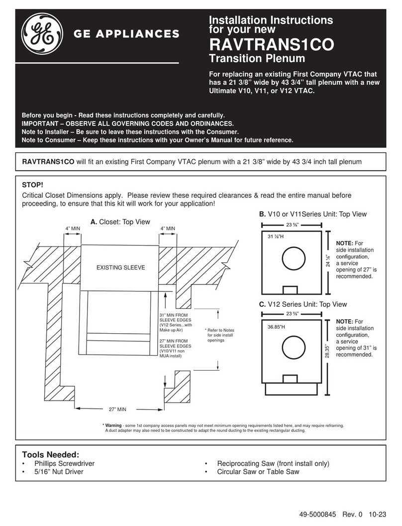
GE CARESCAPE R860 User manual

gehealthcare.com
CARESCAPE™
R860 Ventilator
O2 Therapy Quick Guide

2
Notice
The materials contained in this document are intended for educational purposes only. This document does not
establish specifications, operating procedures or maintenance methods for any of the products referenced.
Always refer to the official written materials (labeling) provided with the product for specifications, operating
procedures and maintenance requirements. No diagnostic statements are inferred or included in this material.
All clinical diagnoses should be made by a trained physician or clinician.

3
Contents
Equipment Required for High Flow Oxygen Therapy on the CARESCAPE R860 Ventilator .................4
High Flow Oxygen Therapy Set-up on the CARESCAPE R860 Ventilator . . . . . . . . . . . . . . . . . . . . . . . . . . . . . . . . . .5
High Flow Oxygen Therapy System Check ...............................................................6
Starting High Flow Oxygen Therapy After System Start-up . . . . . . . . . . . . . . . . . . . . . . . . . . . . . . . . . . . . . . . . . . . . . .8
Starting O2 Therapy from Invasive or Noninvasive Ventilation ......................................... 10
Navigating O2 Therapy Present View .................................................................. 11
Stopping High Flow Oxygen Therapy .................................................................. 11
Stopping High Flow Oxygen Therapy to Begin Invasive or Noninvasive Ventilation . . . . . . . . . . . . . . . . . . . . . 12
Conclusion ............................................................................................13
Note! Always refer to the User Reference Manual before use. Refer to the User Reference Manual
for information on all warnings and precautions.

4
Oftentimes when a patient presents with acute respiratory failure, a clinician will decide what type of
ventilatory support that should be used based on the severity of the patient’s disease. Noninvasive
respiratory support such as high flow oxygen therapy, noninvasive ventilation, and CPAP are alternatives to
intubation and mechanical ventilation with patients who have respiratory failure. High flow oxygen therapy
delivers heated humidified gas at a set FiO2 and flow rate through an unsealed patient interface. High flow
oxygen therapy offers a number of physiological benefits such as pharyngeal dead space washout, work
of breathing reduction, PEEP effect, constant FiO2 and improvement of mucociliary clearance and patient
comfort. The CARESCAPE R860 Ventilator offers integrated high flow oxygen therapy, which allows clinicians
to seamlessly transition from high flow oxygen therapy to mechanical ventilation and back again.
Equipment Required for High Flow Oxygen Therapy
on the CARESCAPE R860 Ventilator
1. CARESCAPE R860 Ventilator
2. Single-limb or dual-limb circuit
3. Fisher & Paykel MR850 humidifier
4. Unsealed patient interface (F&P nasal cannula)
CARESCAPE R860
EXP
P
aux
-20- +120
hPa(cmH0)
3 4
1
2

5
High Flow Oxygen Therapy Set-up on the
CARESCAPE R860 Ventilator
Single-limb Circuit Set-up
1. Slide the humidification chamber onto the humidifier base.
2. Connect Circuit Dry Line to humidification chamber and
Inspiratory Safety Guard.
3. Connect the breathing circuit to the humidification chamber.
4. Connect the heater wire adapter (shown) and chamber
outlet temperature probe to the breathing circuit socket.
5. Connect the temperature probe plug to the blue socket
and the heater wire adapter plug to the yellow socket to
the humidifier base until an audible click is heard.
6. Connect the airway temperature probe to the breathing circuit.
7. Connect the patient interface to the breathing circuit.
8. Turn on the humidifier base and select the mode.
Note: The humidifier base should be plugged in.
Note: A continual feed of water should be going to the
humidification chamber to prevent a water out alarm or
a low humidity alarm.
Dual-limb Circuit Set-up
1. Slide the humidification chamber onto the humidifier base.
2. Connect Circuit Dry Line to humidification chamber and
Inspiratory Safety Guard.
3. Connect the inspiratory limb of the breathing circuit to the
humidification chamber and the expiratory limb to the
expiratory valve assembly (EVA).
4. Connect the heater wire adapter (shown) and chamber
outlet temperature probe to the breathing circuit socket.
5. Connect the temperature probe plug to the blue socket,
and the heater wire adapter plug to the yellow socket to
the humidifier base until an audible click is heard.
6. Connect the airway temperature probe (not shown) to
the breathing circuit.
7. Connect the patient interface to the breathing circuit using
a 22 mm adapter at the wye of the breathing circuit.
8. Turn on the humidifier base and set the temperature.
Note: The humidifier base should be plugged in.
Note: A continual feed of water should be going to the
humidification chamber to prevent a water out alarm or
a low humidity alarm.
CARESCAPE R860
EXP
P
aux
-20-+120
hPa(cmH0)
CARESCAPE R860
EXP
P
aux
-20-+120
hPa(cmH0)
2
2
3
3
1
1
4
4
6
6
7
7
5
5
For additional information on the humidifier set-up and operation,
please refer to the Fisher & Paykel MR 850 User’s Manual.

6
1
High Flow Oxygen Therapy System Check
Be sure that the ventilator is prepared for mechanical ventilation
in an emergency scenario. It is recommended that a full
(dual-limb) system check be completed prior to use of the
O2 Therapy feature with a single-limb configuration.
To ensure the proper function of the system, it is highly
recommended to complete a System Check before use and
between patients. Failure to complete a System Check may
result in inaccurate delivery and monitoring.
Note: O2 Therapy is allowed even if the safety relief valve test
fails during the system check.
Dual-limb Circuit
1. From Standby, select SYSTEM CHECK.
Note: The Run System Check menu shows.
2. Select the dual-limb circuit icon.
3. Attach the dual-limb breathing circuit and all accessories
that will be used during O2 Therapy.
Note: An inspiratory safety guard must be installed on the
inspiratory port and any accessories that will be used. Do not
attach any accessories that prevent attachment of the patient
wye to the occlusion port.
4. Occlude the patient wye using the occlusion port.
Note: The occlusion port sits below the exhalation valve
assembly.
5. Select Start.
6. Select the information icon to see the System Check
Details menu.
a. As the system check is running, the results of each
check will be displayed.
Note: Follow all on-screen system check instructions. A green
check mark will display if the check passes. If the check fails,
a red X is shown, and a Help icon displays next to the failed
check to provide possible causes and help for troubleshooting.
The System Check results show the dual-limb circuit icon, the
result of the check, and the date and time of the check.
7. Select START O2 THERAPY to begin delivery of Oxygen.
8. Confirm Oxygen is flowing through the patient circuit
before connecting to the patient.
1
2
6a
5
7
6

7
1
1
2
5a
4
6
5
High Flow Oxygen Therapy System Check (cont.)
Single-limb Circuit
All checks run during a single-limb check are also run on a
dual-limb system check. There is no need to perform a system
check using a single-limb circuit if a dual-limb check was
performed and passed.
1. From Standby, select SYSTEM CHECK.
Note: The Run System Check menu shows.
2. Select the single-limb circuit icon.
3. Attach the single-limb breathing circuit and all accessories
that will be used during O2 Therapy.
Note: An inspiratory safety guard must be installed on the
inspiratory port and any accessories that will be used.
4. Select Start.
5. Select the information icon to see the System Check
Details menu.
a. As the system check is running the results of each check
will be displayed.
Note: Wait for the System Check to finish. A green check mark
will display if the check passes. If the check fails, a red X is
shown, and a Help icon displays next to the failed check to
provide possible causes and help for troubleshooting. The
System Check results show the dual-limb circuit icon, the result
of the check, and the date and time of the check.
6. Select START O2 THERAPY to begin delivery of Oxygen.
7. Confirm Oxygen is flowing through the patient circuit
before connecting to the patient

8
Starting High Flow Oxygen Therapy After
System Start-up
1. Confirm the appropriate patient circuit and humidified
patient interface is connected to the inspiratory port.
2. Select NEW PATIENT to select the appropriate patient
type and add any additional demographic data.
3. Select Current Mode.
4. Select O2 Therapy from the list of modes.
5. Set the FiO2%.
6. Set the Flow.
7. Select Confirm to confirm O2 Therapy settings.
8. Select Confirm from the O2 Therapy confirmation
WARNING window.
2
3
7
4
8
5 6

9
9
10
Starting High Flow Oxygen Therapy After
System Start-up (cont.)
9. Complete a SYSTEM CHECK for the appropriate
circuit type.
10. Select START O2 THERAPY.
Note: The system delivers Oxygen and the O2 Therapy Present
View shows.

10
Starting O2 Therapy from
Invasive or Noninvasive
Ventilation
1. Confirm the appropriate patient circuit and humidified
patient interface is connected to the inspiratory port.
2. Select Current Mode.
3. Select O2 Therapy from the list of Modes.
4. Set the FiO2%.
5. Set the Flow.
6. Select Confirm to confirm O2 Therapy settings.
7. Select Pause Ventilation from the O2 Therapy confirmation
WARNING window.
8. Confirm a SYSTEM CHECK has been completed for the
appropriate circuit type.
9. Select START O2 THERAPY.
Note: The system delivers Oxygen and the O2 Therapy Present
View shows.
2
4 5
6
7
8 9
3

11
Navigating O2 Therapy
Present View
1. O2 Therapy. Patient alarms disabled in O2 Therapy message.
2. Current FiO2.
3. Pressure bar graph.
4. Standby.
5. Current Flow.
6. Flow setting.
7. FiO2 setting.
8. Current mode, O2 Therapy.
Note: To view patient trends, swipe to the right to the
past/historical data workspace.
Circuit Pressure Bar Graph
The circuit pressure bar graph is not patient airway pressure.
The pressure represents the resistance to flow provided by the
cannula and the applied patient interface and may indicate an
occlusion to the patient interface during oxygen therapy. Make
sure the cannula size is appropriate for the patient. Incorrectly
sized cannulas may cause a partially sealed patient interface
resulting in higher reported pressures.
Stopping High Flow
Oxygen Therapy
1. Safeguard the patient and remove nasal cannula.
2. Select Standby.
3. Select Pause O2 Therapy to go to Standby.
3
1 2
4678
3
2
5

12
Stopping High Flow
Oxygen Therapy to
Begin Invasive or
Noninvasive Ventilation
1. Safeguard the patient.
2. Select Current Mode.
3. Select a mode from the list of modes.
4. Adjust the ventilation mode settings as needed.
5. Select Confirm from the ventilation mode window.
6. Select PAUSE O2 THERAPY from WARNING window.
7. Confirm or complete a SYSTEM CHECK for the dual-limb
circuit type.
Note: If using a single-limb circuit, remove the circuit and
connect a dual-limb circuit to the ventilator.
8. Select START VENTILATION.
Note: A Neonatal Flow Sensor Calibration should be performed
upon returning to Mechanical Ventilation, if the Neonatal Flow
Sensor was not previously calibrated manually or automatically
during a system check using a dual-limb circuit.
2
5
6
7 8
3 4

1. Maggiore SM, et al. Am J Respir Crit Care Med. 2014 Aug 1;190(3):282-8.
Product may not be available in all countries and regions. Full product technical specifications
are available upon request. Contact a GE Healthcare Representative for more information.
Data subject to change.
Please visit http://www.gehealthcare.com.
© 2020 General Electric Company – All rights reserved.
GE Healthcare reserves the right to make changes in specifications and features shown
herein, or discontinue the product described at any time without notice or obligation.
To determine whether individual features are standard or optional, consult with your
GE Healthcare sales representative for the most current information.
GE, the GE Monogram and CARESCAPE are trademarks of General Electric Company.
GE Healthcare, a division of General Electric Company. GE Medical Systems, Inc., doing
business as GE Healthcare.
Reproduction in any form is forbidden without prior written permission from GE.
October 2020
JB00230XX
Conclusion
When used after mechanical ventilation, High Flow Oxygen Therapy has been shown to reduce the risk of reintubation.1
The O2 Therapy mode of the CARESCAPE R860 Ventilator was designed to support clinicians in treating a variety of patients.
Other manuals for CARESCAPE R860
1
Table of contents
Other GE Fan manuals
Popular Fan manuals by other brands

Emerson
Emerson DC BUILDER ES Series owner's manual

Fanimation
Fanimation EMBRACE FPS7955B manual

Casablanca
Casablanca Marrakesh owner's manual

Monte Carlo Fan Company
Monte Carlo Fan Company 3MTR38TMO-L Operation & maintenance manual

Airia
Airia LIFEBREATH RNC200 manual

AirArtDeco
AirArtDeco AADQ-401 instruction manual

Price
Price FFU series Installation and service manual

Monte Carlo Fan Company
Monte Carlo Fan Company 4ICR52XXD Series Owner's guide and installation manual

Lunos
Lunos eGO installation manual

Arbonia
Arbonia 4050160AR Installation and maintenance manual

Haier
Haier FTM010BPG user manual

Faro Barcelona
Faro Barcelona icaria Series manual