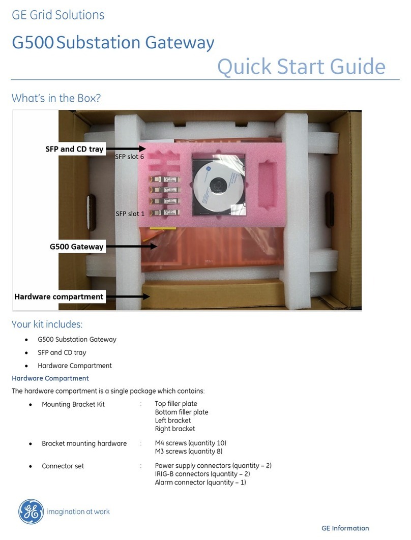
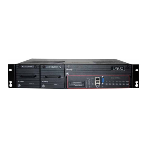
GE G500 User manual

GE
Grid Solutions
GE Information
MultilinTM G500
Substation Gateway
Instruction Manual
994-0152
Version 1.00 Revision 1

GE Grid Solutions
Copyright Notice
© 2019, General Electric Company. All rights reserved.
The information contained in this online publication is the exclusive property of General Electric Company,
except as otherwise indicated. You may view, copy and print documents and graphics incorporated in this online
publication (the “Documents”) subject to the following: (1) the Documents may be used solely for personal, infor-
mational, non-commercial purposes; (2) the Documents may not be modified or altered in any way; and (3) Gen-
eral Electric Company withholds permission for making the Documents or any portion thereof accessible via the
internet. Except as expressly provided herein, you may not use, copy, print, display, reproduce, publish, license,
post, transmit or distribute the Documents in whole or in part without the prior written permission of General
Electric Company.
The information contained in this online publication is proprietary and subject to change without notice. The
software described in this online publication is supplied under license and may be used or copied only in accor-
dance with the terms of such license.
Trademark Notices
GE, Multilin and are trademarks and service marks of General Electric Company.
* Trademarks of General Electric Company.
IEC is a registered trademark of Commission Electrotechnique Internationale. IEEE is a registered trademark of
the Institute of Electrical and Electronics Engineers, Inc. Internet Explorer, Microsoft, and Windows are registered
trademarks of Microsoft Corporation.
Other company or product names mentioned in this document may be trademarks or registered trademarks of
their respective companies.
This printed manual is recyclable.
Please return for recycling where facilities exist.

G500 SUBSTATION GATEWAY INSTRUCTION MANUAL GE INFORMATION 3
G500 Substation Gateway
Table of contents
PRODUCT SUPPORT Access the GE Grid Solutions web site........................................................................7
Search GE Grid Solutions technical support library.................................................7
Contact GE Grid Solutions technical support ...........................................................7
GE Grid Solutions address ............................................................................................8
Product returns...............................................................................................................8
ABOUT THIS
DOCUMENT
Purpose ............................................................................................................................9
Intended audience ........................................................................................................9
Additional documentation ...........................................................................................9
How to use this guide .................................................................................................10
Safety words and definitions......................................................................................10
1. INTRODUCTION Safety precautions ......................................................................................................11
Warning symbols .........................................................................................................12
Hardware overview......................................................................................................12
Order code.....................................................................................................................14
MCP Spares and Accessories......................................................................................15
2. UNPACKING AND
INSPECTION
Electro Static Discharge - ESD ..................................................................................17
Initial inspection ..........................................................................................................18
Unpacking......................................................................................................................18
3. INSTALLING THE
G500
Installation.....................................................................................................................19
Mounting instructions .................................................................................................................................19
General advice ..............................................................................................................23
Grounding......................................................................................................................23
Power Supply Unit (PSU) ..............................................................................................24
High Voltage Power Supply ...................................................................................................................... 24

4 GE INFORMATION G500 SUBSTATION GATEWAY INSTRUCTION MANUAL
TABLE OF CONTENTS
Low Voltage Power Supply........................................................................................................................26
Power-On Self-Test (POST) .........................................................................................................................27
Super Capacitor..............................................................................................................................................27
G500 system redundancy ...........................................................................................27
Fail over sequence ........................................................................................................................................28
Required components .................................................................................................................................28
RS232 switch panel.......................................................................................................................................30
Redundancy wiring diagrams..................................................................................................................30
4. INTERFACES First look at the G500...................................................................................................37
Front panel........................................................................................................................................................37
Rear panel .........................................................................................................................................................38
External Interfaces.......................................................................................................39
USB Slave...........................................................................................................................................................39
Ethernet Port ....................................................................................................................................................39
Reset Button.....................................................................................................................................................40
USB 3.0................................................................................................................................................................40
SD Card...............................................................................................................................................................41
USB 2.0................................................................................................................................................................41
Display Port.......................................................................................................................................................41
Alarm ...................................................................................................................................................................42
IRIG – IN ..............................................................................................................................................................43
IRIG - OUT ..........................................................................................................................................................43
Serial Ports ........................................................................................................................................................44
Ethernet Ports..................................................................................................................................................53
Internal Interfaces........................................................................................................54
Opening cover .................................................................................................................................................54
Closing cover....................................................................................................................................................57
M.2 SSD...............................................................................................................................................................59
PCIe Slots ...........................................................................................................................................................61
USB 2 dongle slot...........................................................................................................................................63
5. INDICATORS Front Indicators ............................................................................................................65
Ethernet..............................................................................................................................................................66
Ethernet Port (SFP) LEDs..............................................................................................................................66
Serial Port LEDs...............................................................................................................................................67
IRIG-B input.......................................................................................................................................................68
IRIG-B output....................................................................................................................................................68
CPU .......................................................................................................................................................................69
TEMP.....................................................................................................................................................................69
SSD........................................................................................................................................................................69
STATUS................................................................................................................................................................70
Power...................................................................................................................................................................70
OLED Display....................................................................................................................................................70
Rear indicators..............................................................................................................71
6. SPECIFICATIONS Product specifications ................................................................................................73
Environmental specifications.....................................................................................74
Temperature and Humidity......................................................................................................................74
Altitude................................................................................................................................................................75
Ingress Protection (IEC 60529) .................................................................................................................75
Liquid Protection ...........................................................................................................................................75

TABLE OF CONTENTS
G500 SUBSTATION GATEWAY INSTRUCTION MANUAL GE INFORMATION 5
Mean Time Between Failure.....................................................................................................................75
Mechanical Specifications ..........................................................................................76
Weight ................................................................................................................................................................76
Dimensions....................................................................................................................................................... 76
General Torque Values for Screws........................................................................................................ 79
Storage recommendations.........................................................................................79
Storage conditions ......................................................................................................................................79
7. REMOVING THE
G500 FROM SERVICE
Remove configuration data and sensitive information from the G500 .............81
Removing configuration data on a PC......................................................................82
A. STANDARDS &
COMPLIANCE
Compliance Standards ................................................................................................83
B. CUL
C. WARRANTY Warranty........................................................................................................................87
D. LIST OF
ACRONYMS
Acronym Definitions ....................................................................................................89
REVISION HISTORY Revision history ............................................................................................................91

6 GE INFORMATION G500 SUBSTATION GATEWAY INSTRUCTION MANUAL
TABLE OF CONTENTS

G500 SUBSTATION GATEWAY INSTRUCTION MANUAL GE INFORMATION 7
G500 Substation Gateway
Product Support
Product Support
If you need help with any aspect of your G500 product, you can:
• Access the G500 Web site
• Search the GE Technical Support library
• Contact Technical Support
Also covered are:
• The G500 address
• Instructions on returning a G500
Access the GE Grid Solutions web site
The G500 Web site provides fast access to technical information, such as manuals, release
notes and knowledge base topics.
Visit us on the Web at: http://www.gegridsolutions.com
Search GE Grid Solutions technical support library
This site serves as a document repository for post-sales requests. To get access to the
Technical Support Web site, go to:
Visit us on the Web at: http://sc.ge.com/*SASTechSupport
Contact GE Grid Solutions technical support
GE Grid Solution Technical Support is open 24 hours a day, seven days a week for you to
talk directly to a GE representative.
In the U.S. and Canada, call toll-free: 1 800-547-8629
International customers, please call: + 1 905-927-7070

8 GE INFORMATION G500 SUBSTATION GATEWAY INSTRUCTION MANUAL
PRODUCT SUPPORT
Or e-mail to multilin.tech@ge.com
Have the following information ready to give to Technical Support:
• Ship to address (the address that the product is to be returned to)
• Bill to address (the address that the invoice is to be sent to)
•Contactname
• Contact phone number
• Contact fax number
• Contact e-mail address
• Product number / serial number
• Description of problem
Technical Support will provide you with a case number for your reference.
GE Grid Solutions address
The GE Grid Solutions company address is:
GE Grid Solutions
650 Markland Street
Markham, Ontario
Canada L6C 0M1
Product returns
A Return Merchandise Authorization (RMA) number must accompany all equipment being
returned for repair, servicing, or for any other reason. Before you return a product, please
contact GE’s Grid Solutions to obtain an RMA number and instructions for return
shipments.
You are sent the RMA number and RMA documents via fax or e-mail. Once you receive the
RMA documents, attach them to the outside of the shipping package and ship to GE.
NOTE
Product returns are not accepted unless accompanied by the Return Merchandise
Authorization number.

G500 SUBSTATION GATEWAY INSTRUCTION MANUAL GE INFORMATION 9
G500 Substation Gateway
About this Document
About this Document
Purpose
This manual provides information about installing, setting up, using and maintaining your
G500 Substation Gateway. This manual does not provide any procedures for configuring
the G500 software.
Intended audience
This manual is intended for use by field technicians and maintenance personnel who are
responsible for the installation, wiring and maintenance of SCADA equipment. This guide
assumes that the user is experienced in:
• Electrical utility applications
• Electrical wiring and safety procedures
• Related other manufacturers’ products, such as protective relays and
communications equipment
Additional documentation
For further information about the G500, refer to the following documents.
•G500 Online Help
• Module layouts, as available
•TheG500 Substation Gateway Software Configuration Guide (GE part number
SWM0101).
For the current version of the G500 Instruction Manual, please download a copy from:
http://www.gegridsolutions.com/app/ViewFiles.aspx?prod=G500&type=3

10 GE INFORMATION G500 SUBSTATION GATEWAY INSTRUCTION MANUAL
ABOUT THIS DOCUMENT
How to use this guide
This guide describes how to install the G500.
Procedures are provided for all component options available for the G500. The
components included in your G500 depend on what was ordered for your substation
application. Follow only the procedures that apply to your G500 model. To check what
options are included in your G500, see See “Order code” on page 14.
Safety words and definitions
Before attempting to install or use the device, review all safety indicators in this document
to help prevent injury, equipment damage or downtime.
The following safety and equipment symbols are used in this document:
Indicates a hazardous situation which, if not avoided, result in death or serious injury.
Indicates a hazardous situation which, if not avoided, could result in death or serious
injury.
Indicates a hazardous situation which, if not avoided, could result in minor or
moderate injury.
Indicates practices that are not related to personal injury.

G500 SUBSTATION GATEWAY INSTRUCTION MANUAL GE INFORMATION 11
G500 Substation Gateway
Chapter 1: Introduction
Introduction
Before you begin installing and using the G500, review the information in this chapter,
including the following topics:
• Safety precautions
• Warning Symbols
• Hardware overview
•OrderCode
Read and thoroughly understand this guide before installing and operating the unit. Save
these instructions for later use and reference.
Failure to observe the instructions in this manual may result in serious injury or death.
Safety precautions
Follow all safety precautions and instructions in this manual.
Only qualified personnel should work on the G500. Maintenance personnel should be
familiar with the technology and the hazards associated with electrical equipment.
•Never work alone.
• Before performing visual inspections, tests, or maintenance on this equipment, isolate
or disconnect all hazardous live circuits and sources of electric power. Assume that all
circuits are live until they have been completely de-energized, tested, and tagged. Pay
particular attention to the design of the power system. Consider all sources of power,
including the possibility of back feed.
• Turn off all power supplying the equipment in which the G500 is to be installed before
installing and wiring the G500.
• Operate only from the power source specified on the installed power supply module.
• Beware of potential hazards and wear personal protective equipment.
• The successful operation of this equipment depends upon proper handling,
installation, and operation. Neglecting fundamental installation requirements may
lead to personal injury as well as damage to electrical equipment or other property.

12 GE INFORMATION G500 SUBSTATION GATEWAY INSTRUCTION MANUAL
CHAPTER 1: INTRODUCTION
• All electronic components within the G500 are susceptible to damage from
electrostatic discharge. To prevent damage when handling this product use approved
static control procedures.
• Hazardous voltages can cause shock, burns or death. To prevent exposure to
hazardous voltages, disconnect and lock out all power sources before servicing and
removing components.
• If the G500 is used in a manner not specified in this manual, the protection provided
by the equipment may be impaired.
• Changes or modifications made to the unit not authorized by GE could void the
warranty.
Warning symbols
Table 1 explains the meaning of warning symbols that may appear on the G500 or in this
manual.
Table 1: Warning symbols that appear on the G500 and in this manual
The relevant circuit is direct current.
The relevant circuit is alternating current.
!
Caution: Refer to the documentation for important operation and
maintenance instructions. Failure to take or avoid specified actions
could result in loss of data or physical damage.
Warning: Dangerous voltage constituting risk of electric shock is
present within the unit. Failure to take or avoid specified actions could
result in physical harm to the user.
Earth/Ground Terminal
Protective Ground Terminal
Caution: Hot Surface
Hardware overview
The G500 is built on a flexible, high-performance, upgradeable COM express platform
powered by one of two CPU modules, either an AMD RX-427BB 4-core 2.7GHz (max turbo
frequency 3.6 GHz) CPU with 16 Gigabytes of soldered on DDR3 ECC memory for best
performance at a limited (+60°C) maximum operating temperature, or an AMD RX-225FB 2
core 2.2 GHz (max turbo frequency 3.0 GHz) CPU with 8 Gigabytes of soldered on DDR3 ECC
for a wider operating temperature (+70°C). The G500 is distinguished by the noticeable lack
of a hard drive and fan, employing instead the rugged and reliable Solid State Drive (SSD)
mass storage and engineered heat sink.
Symbol Description

CHAPTER 1: INTRODUCTION
G500 SUBSTATION GATEWAY INSTRUCTION MANUAL GE INFORMATION 13
The G500 supports various communication media types through a choice of input/output
(I/0):
• Serial: 8 factory installed ports, expandable up to 20 ports, RS-232 and RS-485 are
accessible via individual RJ45 connectors.
•Ethernet: Six Ethernet interfaces available through SFP cages. Each cage supports:
100/1000BaseT, 100BaseFX or 1000BaseSX.
Figure 1: G500

14 GE INFORMATION G500 SUBSTATION GATEWAY INSTRUCTION MANUAL
CHAPTER 1: INTRODUCTION
Order code
* Storage option A is only available with CPU option A and storage option B is only available
with CPU option B.
** Visit the online store for application licenses ordering codes.
For latest configuration and options, please visit the online store:
http://www.gegridsolutions.com/app/ViewFiles.aspx?prod=G500&type=3.

CHAPTER 1: INTRODUCTION
G500 SUBSTATION GATEWAY INSTRUCTION MANUAL GE INFORMATION 15
MCP Spares and Accessories
MCP-S -*-* Description
Spare type
1 |SFP Transceiver
2|Power Supply
3 |UART Card
SFP Transceiver options
A
SFP Module 100BASE-FX LC TRANSCEIVER OPTICAL
MULTI-MODE 1300nm -40 TO 85C [580-3784] These options are only
available when Spare
type is SFP
Transceiver
B
SFP Module 1000BASE-SX LC TRANSCEIVER OPTICAL
MULTI-MODE 1310nm -40 TO 85C [580-3785]
C
SFP Module 100/1000BASE-T RJ45 TRANSCEIVER
COPPER -40 TO 85C W/WO RX_LOS [580-3786]
Power Supply Options
H MCP PSU, HV 90-264 VAC/88-330VDC [528-2001LF-CC] These options are only
available when Spare
type is Power Supply
L MCP PSU, LV 18-60VDC [528-2002LF-CC]
UART Card options
S
MCP PCIe UART CARD, 4x PORT (RJ45) RS232/485 [528-
1001LF] These options are only
available when Spare
type is UART Card
R
MCP BUILT-IN UART CARD, 4x PORT (RJ45) RS232/485
[528-1003LF]

16 GE INFORMATION G500 SUBSTATION GATEWAY INSTRUCTION MANUAL
CHAPTER 1: INTRODUCTION

G500 SUBSTATION GATEWAY INSTRUCTION MANUAL GE INFORMATION 17
G500 Substation Gateway
Chapter 2: Unpacking and Inspection
Unpacking and I nspection
This chapter covers the suggested inspection and preparation considerations and
background information necessary prior to using the G500. Unpacking, initial inspection,
and first time operation of the G500 are covered. Following the procedures given in the
chapter is recommended, and they will verify proper operation before the product is
integrated into your system.
Hot Surface: During operation of the G500 the surface of the heat sink, can reach a
temperature of 60°C and above. Therefore, be careful and do not touch it with bare
fingers.
Electro Static Discharge - ESD
The discharge of static electricity, known as Electro Static Discharge or ESD, is a major
cause of electronic component failure. The Industrial Computer has been packed in a
static-safe bag which protects it from ESD while it is in the bag. Before removing the
Boards or any other electronic product from its static-safe bag, be prepared to handle it in
a static-safe environment.
You should wear a properly-functioning anti-static strap and ensure you are fully
grounded. Any surface upon which you place on the unprotected G500 should be static-
safe, usually facilitated by the use of anti-static mats. From the time the board is removed
from the anti-static bag until it is in the card cage and functioning properly, extreme care
should be taken to avoid “zapping” the board with ESD. You should be aware that you
could “zap” the board without you knowing it; a small discharge, imperceptible to the eye
and touch, can often be enough to damage electronic components. Extra caution should
be taken in cold and dry weather when electrostatic charge easily builds up.

18 GE INFORMATION G500 SUBSTATION GATEWAY INSTRUCTION MANUAL
CHAPTER 2: UNPACKING AND INSPECTION
Only after ensuring that both you and the surrounding area are protected from ESD,
carefully remove the board or module from the shipping carton by grasping the module on
its edges. Place the board, in its anti-static bag, flat down on a suitable surface. You may
then remove the board from the anti-static bag by tearing the ESD warning labels.
Initial inspection
After unpacking the products, you should inspect it for visible damage that could have
occurred during shipping or unpacking. If damage is observed (usually in the form of bent
component leads or loose socketed components), contact GE Technical Support for
additional instructions. Depending on the severity of the damage, it may be necessary to
return the product to the factory for repair.
DO NOT apply power to the board if it has visible damage!
Doing so may cause further, possibly irreparable damage, as well as introduce a fire or
shock hazard.
Unpacking
Please read the manual carefully before unpacking the board or module or fitting the
device into your system. Also adhere to the following:
• Observe all precautions for electrostatic sensitive modules
• Do not place the board on conductive surfaces, anti-static plastic, or sponge, which
can cause shocks and lead to board trace damage.
• Do not exceed the specified operational temperatures.
• Keep all original packaging material for future storage or warranty shipments of the
board.
Although the products are carefully packaged to protect against the rigors of shipping, it is
still possible that shipping damage can occur. Careful inspection of the shipping carton
should reveal some information about how the package was handled by the shipping
service. If evidence of damage or rough handling is found, you should notify the shipping
service and GE Technical Support as soon as possible.
NOTE
PCIe Cards and storage devices may also have temperature restrictions
Retain all packing material in case of future need.
Before installing or removing any board, please ensure that the system power and
external supplies have been turned off!

G500 SUBSTATION GATEWAY INSTRUCTION MANUAL GE INFORMATION 19
G500 Substation Gateway
Chapter 3: Installing the G500
Instal ling the G 500
This chapter covers the installation of the Industrial Computer and initial power-on
operations.
Before you install and operate the G500, read and follow the safety guidelines and
instructions in “Safety precautions” on page 11.
Installation
Mounting instructions
The G500 is mounted in 3U slot of a 19” rack by use of 6 screws compliant to IEC60297-3
with STD hole Pattern.
Screws Use screws with a shaft diameter close to 5mm. For example, M5 or UNF 10-32 screws.

20 GE INFORMATION G500 SUBSTATION GATEWAY INSTRUCTION MANUAL
CHAPTER 3: INSTALLING THE G500
Mounting Diagram 1. Mount the brackets on the unit:
NOTE
For screw torque specification, refer to “General Torque Values for Screws” on page 79.
2. Install 2 of the screws at the same height in the 19” rack. The screws should be
screwed in to a distance of about 3 mm between screw head and rack.
Other manuals for G500
1
Table of contents
Other GE Gateway manuals

GE
GE ProBridge User manual

GE
GE Multilin D400 User manual

GE
GE MDS WiYZ User manual

GE
GE GCG001 User manual

GE
GE Multilin D400 Instructions for use

GE
GE GFK-2892F User manual

GE
GE POWER LEADER GEH-6505A User manual

GE
GE NX-592E-GSM User manual

GE
GE Multilin D400 User manual

GE
GE PACSystems RX3i Genius User manual
Popular Gateway manuals by other brands

LumiRing
LumiRing WIRELESS WIEGAND WW-Gate manual

ACT'L
ACT'L eWON2001CD installation guide

Calypso Instruments
Calypso Instruments NMEA CONNECT PLUS manual

Falcon
Falcon FDS-Wi user guide

RTA
RTA 460MMBMS-N700 Product user guide

Lucent Technologies
Lucent Technologies AnyMedia Line Access Gateway Brochure & specs