GE Multilin D400 Instructions for use

GE
Digital Energy
GE Information
D400
Substation Gateway
Hardware User’s Manual
994-0089
Version 1.30 Revision 9

GE Digital Energy
Copyright Notice
© 2006-2013, General Electric Company. All rights reserved.
The information contained in this online publication is the exclusive property of General Electric Company,
exceptasotherwise indicated.Youmayview,copyandprintdocumentsandgraphicsincorporatedinthisonline
publication (the "Documents") subject to the following: (1) the Documents may be used solely for personal, infor-
mational, non-commercial purposes; (2) the Documents may not be modified or altered in any way; and (3) Gen-
eral Electric Company withholds permission for makingthe Documents or any portion thereof accessible via the
internet. Except as expressly provided herein, you may notuse, copy,print, display, reproduce, publish, license,
post, transmit or distribute the Documents in whole or in part without the prior written permission of General
Electric Company.
The information contained in this online publication is proprietary and subject to change without notice. The
software described in this online publication is supplied under license and may be used or copied onlyin accor-
dance with the terms of such license.
Trademark Notices
GE and are trademarks and service marks of General Electric Company.
* Trademarks of General Electric Company.
CompactFlash is a registered trademark of SanDisk Corporation. ERNI is a registered trademark of ERNI Elek-
troapparate GMBH. Hyperterminal is a registered trademark of Hilgraeve, Incorporated. TeraTerm is a registered
trademark of T. Teranishi, IEC is a registered trademark of Commission Electrotechnique Internationale. IEEE isa
registered trademark of the Institute of Electrical and Electronics Engineers, Inc. Internet Explorer, Microsoft, and
Windows are registered trademarks of Microsoft Corporation. JAVA and J2SE are registered trademarks of Sun
Microsystems, Inc. Maxell is a registered trademark of Hitachi Maxell, Ltd. MiniSQL is a trademark of Hughes
Technologies. Netscape is a registered trademark of Netscape Communications Corporation. Modbus is a regis-
tered trademark of Schneider Automation Inc. Panduit isa registered trademark of Panduit Corp. Saft is a regis-
teredtrademarkofSAFT sociétéanonyme.SELisaregisteredtrademarkofSchweitzerEngineeringLaboratories,
Inc. Silicon Systems is a registered trademark of Silicon Systems, Inc. Sonnenschein is a registered trademark of
Deutsche Exide GMBH. Tadiran is a registered trademark of Tadiran Israel Electronics Industries Ltd. Toshiba is a
registered trademark of Kabushiki Kaisha Toshiba, doing business as Toshiba Corporation. VESA is registered
trademark of Video Electronics Standards Association Corporation.
Other company or product names mentioned in this document may be trademarks or registered trademarks of
their respective companies.
This printed manual is recyclable.
Please return for recycling where facilities exist.

D400 SUBSTATION GATEWAY USER’S MANUAL GENERAL 3
D400 Substation Gateway
Table of contents
ABOUT THIS
DOCUMENT Purpose ............................................................................................................................7
Intended audience ........................................................................................................7
Additional documentation ...........................................................................................7
How to use this guide ...................................................................................................8
Document conventions.................................................................................................8
Safety words and definitions........................................................................................9
PRODUCT SUPPORT Search technical support ...........................................................................................11
Contact customer support ........................................................................................11
Product returns.............................................................................................................12
Upgrade your D400 Substation Gateway firmware...............................................12
BEFORE YOU START Safety precautions ......................................................................................................13
Warning symbols .........................................................................................................................................14
Regulatory compliance information ........................................................................14
CE Mark compliance....................................................................................................................................14
Restriction of Hazardous Substances (RoHS)...................................................................................15
Product overview..........................................................................................................16
Hardware overview......................................................................................................................................16
Features.............................................................................................................................................................17
Ordering guide..............................................................................................................17
Upgrade kit.......................................................................................................................................................18
Product identification number................................................................................................................19
Product specifications ................................................................................................20
Storage recommendations.........................................................................................23
Storage conditions ......................................................................................................................................23
Battery life.........................................................................................................................................................23
INSTALLING THE
D400 Installation steps..........................................................................................................25
Required tools...............................................................................................................26

4 GENERAL D400 SUBSTATION GATEWAY USER’S MANUAL
TABLE OF CONTENTS
Unpacking the D400.....................................................................................................26
Package contents..........................................................................................................................................26
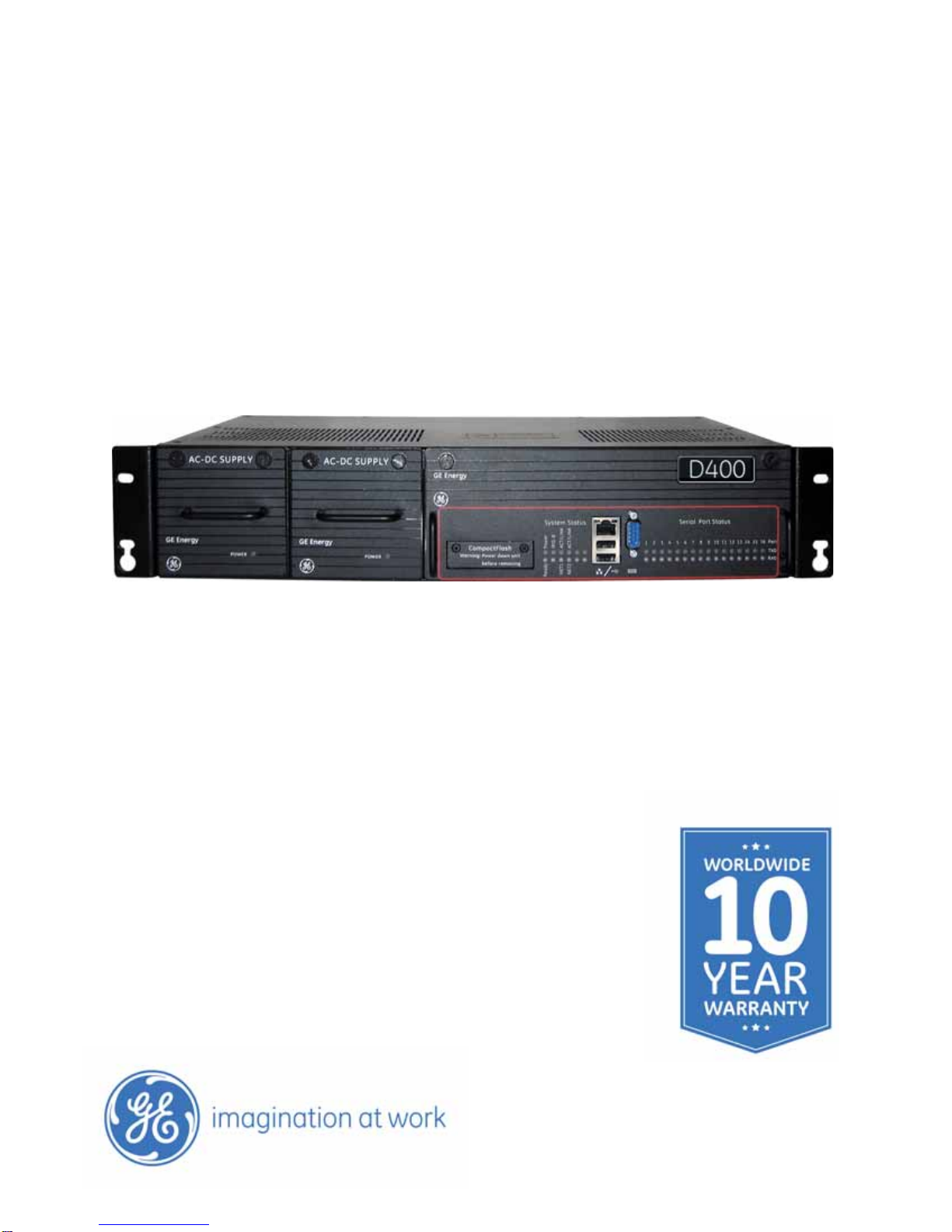
First look at the D400...................................................................................................27
Front Panel........................................................................................................................................................27
Rear panel.........................................................................................................................................................27
Physical installation.....................................................................................................28
Rack mounting................................................................................................................................................28
Panel mount.....................................................................................................................................................29
Battery installation........................................................................................................................................29
Battery removal..............................................................................................................................................29
SETTING UP
COMMUNICATION
CARDS
Communication cards.................................................................................................31
Types of communication cards...............................................................................................................32
Changing card settings...............................................................................................32
RS-232 adapter .............................................................................................................33
Configuration options..................................................................................................................................33
Factory default................................................................................................................................................33
Switch SW1/SW2 configuration..............................................................................................................34
Switch SW3/SW4 configuration..............................................................................................................35
RS-485 adapter .............................................................................................................37
Configuration options..................................................................................................................................37
Factory default................................................................................................................................................37
Switch SW1/SW2 configuration..............................................................................................................37
Switch SW3/SW4 configuration..............................................................................................................38
Fiber optic serial adapter............................................................................................40
Configuration options..................................................................................................................................40
Factory default................................................................................................................................................40
Switch SW1 configuration.........................................................................................................................40
IRIG-B input adapter....................................................................................................42
Configuration options..................................................................................................................................42
Factory default................................................................................................................................................42
Switch SW1 configuration.........................................................................................................................42
Switch SW2 configuration.........................................................................................................................43
IRIG-B distribution adapter ........................................................................................44
Output Voltage................................................................................................................................................44
Configuration options..................................................................................................................................44
4-Port twisted-pair ethernet switch.........................................................................45
Configuration options..................................................................................................................................45
10Base-FL hot standby fiber optic ethernet switch...............................................46
Configuration options..................................................................................................................................46
100Base-FX hot standby fiber optic ethernet adapter .........................................47
Configuration options..................................................................................................................................47
COM2 port adapter ......................................................................................................48
Configuration options..................................................................................................................................48
Redundant twisted-pair ethernet + COM2 port adapter......................................49
Configuration options..................................................................................................................................49
USB KVM and audio adapter.......................................................................................50
Configuration options..................................................................................................................................50
CONNECTING TO
DEVICES AND
NETWORKS
Connection types..........................................................................................................51
Serial....................................................................................................................................................................51
Network..............................................................................................................................................................52

TABLE OF CONTENTS
D400 SUBSTATION GATEWAY USER’S MANUAL GENERAL 5
Time synchronization..................................................................................................52
Local substation computer.......................................................................................................................52
Local maintenance ......................................................................................................................................52
Cabling overview..........................................................................................................52
General cabling requirements................................................................................................................53
High-voltage installations.........................................................................................................................53
RS-232 connections......................................................................................................53
RS-485 connections......................................................................................................54
Cabling requirements..................................................................................................................................55
2-Wire connections......................................................................................................................................55
4-Wire connections......................................................................................................................................56
Fiber optic serial connections....................................................................................57
Glass optical fiber..........................................................................................................................................57
Plastic optical fiber.......................................................................................................................................58
IRIG-B connections.......................................................................................................58
IRIG-B input adapter....................................................................................................................................58
IRIG-B distribution adapter.......................................................................................................................59
Hot standby fiber optic connections ........................................................................60
Network connections...................................................................................................61
Front network port........................................................................................................................................61
Modem connections.....................................................................................................63
Local HMI connection..................................................................................................64
Front maintenance port..............................................................................................65
Minimal required connection...................................................................................................................66
D400 system redundancy...........................................................................................66
Failover sequence.........................................................................................................................................66
Required components.................................................................................................................................67
RS232 switch panel......................................................................................................................................68
Redundancy wiring diagrams.................................................................................................................69
POWERING UP THE
D400 Power supply options ..................................................................................................75
Redundant power supply..........................................................................................................................76
Power configurations..................................................................................................................................76
Power input ranges......................................................................................................................................76
Power connections.......................................................................................................76
Wiring requirements....................................................................................................................................77
External power requirements..................................................................................................................77
Power supply alarms ...................................................................................................79
Power fail alarm ............................................................................................................................................80
System fail alarm...........................................................................................................................................81
Powering down the D400 ...........................................................................................82
SETTING UP THE
D400 Connecting to the D400 for the first time................................................................83
Setting up the network interface .............................................................................85
Creating administrator-level user accounts...........................................................87
Setting up secure web access....................................................................................87
Prerequisites....................................................................................................................................................87
Requesting a certificate.............................................................................................................................87
Installing the certificate and key............................................................................................................88
Testing the network connection................................................................................89

6 GENERAL D400 SUBSTATION GATEWAY USER’S MANUAL
TABLE OF CONTENTS
USING THE D400 Front panel LEDs...........................................................................................................91
System status LEDs.......................................................................................................................................92
Serial port status LEDs.................................................................................................................................92
Substation HMI..............................................................................................................92
D400 HMI...........................................................................................................................................................93
Local HMI...........................................................................................................................................................94
System utilities..............................................................................................................95
From the front maintenance port..........................................................................................................95
From the local substation computer....................................................................................................95
Over a network connection.......................................................................................................................95
File transfer ...................................................................................................................96
USB portable memory device..................................................................................................................96
System status points ...................................................................................................97
Shutting down the D400..............................................................................................98
SERVICINGTHED400 Removing the D400 main module.............................................................................99
Replacing the battery............................................................................................... 100
Before you remove the battery….........................................................................................................100
Supported battery types..........................................................................................................................101
To insert or replace the D400 battery...............................................................................................101
Checking voltage.........................................................................................................................................101
Cleaning and handling Lithium batteries........................................................................................102
Recycling of batteries ...............................................................................................................................102
Battery life......................................................................................................................................................102
Dual ethernet upgrade kit with card 580-2717................................................... 102
Valid combinations.....................................................................................................................................102
Installing the 580-2717 dual ethernet card ...................................................................................103
Dual ethernet upgrade kit with card 580-3410................................................... 105
Valid combinations.....................................................................................................................................105
Installing the 580-3410 dual ethernet card ...................................................................................105
Changing the CompactFlash .................................................................................. 107
Replacing the power supply.................................................................................... 109
STANDARDS &
PROTECTION Compliance standards ............................................................................................. 111
LIST OF ACRONYMS Acronym Definitions ................................................................................................. 115

D400 SUBSTATION GATEWAY USER’S MANUAL GENERAL 7
D400 Substation Gateway
About this Document
About this Document
Purpose
This manual provides information about installing, setting up, using and maintaining your
D400TM SubstationGateway.Thismanualdoes notprovideanyproceduresforconfiguring
the software of the D400.
Intended audience
This manual is intended for use by field technicians and maintenance personnel who are
responsible for the installation, wiring and maintenance of SCADA equipment. This guide
assumes that the user is experiencedin:
• Electrical utility applications
• Electrical wiring and safety procedures
• Related other manufacturers’ products, such as protective relays and
communications equipment
Additional documentation
For further information about the D400, refer to the following documents.
•D400 Substation Gateway Software Configuration Guide (SWM0066)
•D400 online Help
• Module layouts, as available
For the most currentversion of the D400 Hardware User's Manual, please download a
copy from:
http://www.gedigitalenergy.com/app/ViewFiles.aspx?prod=d400&type=3

8 GENERAL D400 SUBSTATION GATEWAY USER’S MANUAL
HOW TO USE THIS GUIDE ABOUT THIS DOCUMENT
How to use this guide
This guide describes how to install the D400 and get it up and running for the first time.
Procedures are provided for all component options available forthe D400. The
components included in your D400 depend on what was ordered foryour substation
application. Follow only the procedures thatapply to your D400 model. To check what
options are included in yourD400, see See “Ordering guide” on page 15..
The software-related procedures in this guide are based on using a computer running
Windows®XP. Some steps and dialog boxes may vary slightly if you are using another
version of Windows.
Document conventions
The following typographic conventions are used throughout this manual:
Bold face is used for:
• Names of software program menus, editors, and dialog boxes; also for the names of
menu commands, keyboardkeys, icons and desktop shortcuts, and buttons and fields
in editors and dialog boxes
• Names of hardware components
• User input that must be typed exactly
Italic face is used for:
•Emphasis
• Cross-references to sections, figures and tables within this manual and for titles of
other documents
• File and directory names; examples of directory paths are generally given in the
Windows format
• Placeholders for user input that is specific to the user. May also include angle brackets
around the placeholder if the placeholder is already in italic text. For example,
c:\<product>\product.def
• References to a parameter or field valueshown

ABOUT THIS DOCUMENT SAFETY WORDS AND DEFINITIONS
D400 SUBSTATION GATEWAY USER’S MANUAL GENERAL 9
Safety words and definitions
Before attempting to install or use the device, review all safety indicators in this document
to help prevent injury, equipment damage or downtime.
The following safety and equipment symbols are used in this document:
Indicates a hazardous situation which, if not avoided, will result in death or serious
injury.
Indicates a hazardous situation which, if not avoided, could result in death or serious
injury.
Indicates a hazardous situation which, if not avoided, could result in minor or
moderate injury.
Indicates practices that are not related to personal injury.

10 GENERAL D400 SUBSTATION GATEWAY USER’S MANUAL
SAFETY WORDS AND DEFINITIONS ABOUT THIS DOCUMENT

D400 SUBSTATION GATEWAY USER’S MANUAL GENERAL 11
D400 Substation Gateway
Product Support
Product Support
If you need help with any aspect of your GE Digital Energy product, you have a few options.
Search technical support
The GE Digital Energy Web site provides fast access to technical information, such as
manuals, release notes and knowledge base topics at:
http://www.gedigitalenergy.com
Contact customer support
The GE Digital Energy Customer Service Center is open 24 hours a day, seven days a week
for you to talk directly to a GE representative.
In the U.S. and Canada, call toll-free: 1 800 547 8629
International customers, please call: + 1 905 927 7070
Have the following information ready to give to Customer Service:
• Ship to address (the address that the product is to be returned to)
• Bill to address (the address that the invoice is to be sent to)
•Contactname
• Contact phone number
• Contact fax number
• Contact e-mail address
• Product number / serial number
• Description of problem
The Customer Service centre will provide you with a case number for your reference.

12 GENERAL D400 SUBSTATION GATEWAY USER’S MANUAL
PRODUCT RETURNS PRODUCT SUPPORT
Product returns
A Return Merchandise Authorization (RMA) number must accompany all equipment being
returned for repair, servicing, or for any other reason. Before you return a product, please
contact GE Digital Energy to obtain an RMA number and instructions for return shipments.
You will be sent the RMA number and RMA documents via fax or e-mail. Once you receive
the RMA documents, attach them to the outside of the shipping package and ship to GE.
NOTE
Product returns will not be accepted unless accompanied by the Return Merchandise
Authorization number.
Upgrade your D400 Substation Gateway firmware
The firmware of your D400 Substation Gateway can be upgraded to provide the latest
functionality and improvements. Visit the customer support web site at http://
www.gedigitalenergy.com to download the upgrade software and instruction guide.

D400 SUBSTATION GATEWAY USER’S MANUAL GENERAL 13
D400 Substation Gateway
Chapter 1: Before You Start
Befo re You Sta rt
Before you begin installing and using the D400, review the information in this chapter,
including the following topics:
• Safety precautions
• Regulatory compliance information
• Product overview
• Product specifications
• Storage recommendations
Read and thoroughly understand this guide beforeinstalling and operating the unit. Save
these instructions for later use and reference.
Failure to observe the instructions in this manual may result in serious injury or death.
Safety precautions
Follow all safety precautions and instructions in this manual.
Only qualified personnel should work on the D400. Maintenance personnel should be
familiar with the technology and the hazards associated with electrical equipment.
•Never work alone.
• Beforeperformingvisual inspections, tests, ormaintenance on this equipment, isolate
or disconnect all hazardous live circuits and sources of electric power. Assume that all
circuits are live until they have been completely de-energized, tested, and tagged. Pay
particular attention to the design of the power system. Consider all sources of power,
including the possibility of back feed.
• Turn off all power supplying the equipment in which the D400 is to be installed before
installing and wiring the D400.
• Operate only from the power source specified on the installed power supply module.
• Beware of potential hazards and wear personal protective equipment.
• The successful operation of this equipment depends upon proper handling,
installation, and operation. Neglecting fundamental installation requirements may
lead to personal injury as well as damage to electrical equipment or other property.

14 GENERAL D400 SUBSTATION GATEWAY USER’S MANUAL
REGULATORY COMPLIANCE INFORMATION CHAPTER 1: BEFORE YOU START
• AllACvoltage terminals areprotected fromaccidental contact bya mechanicalsafety
shield.
• All electronic components within the D400 are susceptible to damage from
electrostatic discharge. To prevent damage when handling this product use approved
static control procedures.
• Hazardous voltages can cause shock, burns or death. To prevent exposure to
hazardous voltages, disconnect and lock out all power sources before servicing and
removing components.
• If the D400 is used in a manner not specified in this manual, the protection provided
by the equipment may be impaired.
• Changes or modifications made to the unit not authorized by GE Digital Energy could
void the warranty.
Warning symbols
The following table explains the meaning of warning symbols that may appear on the
D400 or in this manual.
Table 1: Warning symbols that appear on the D400 and in this manual
Regulatory compliance information
CE Mark compliance
The D400 is rated as CISPR 11 Group1 Class "A" equipment.
NOTE
To provide higher EMC immunity and maintain CE Mark compliance, the serial cables used
for permanent RS-232 and RS-485 connections must comply with the following
requirements:
• Cables must be shielded
• Dtype connector covers mustprovideEMC shielding(e.g. metallized plasticor die cast
metal covers) for permanently connected RS-232 cables
The relevant circuit is direct current.
The relevant circuit is alternating current.
Caution: Refer to the documentation for important operation and
maintenance instructions. Failure to take or avoid specified actions
could result in loss of data or physical damage.
Warning: Dangerous voltage constituting risk of electric shock is
present within the unit. Failure to take or avoid specified actions
could result in physical harm to the user.
Earth/Ground Terminal
Protective Ground Terminal
Caution: Hot Surface
!

CHAPTER 1: BEFORE YOU START REGULATORY COMPLIANCE INFORMATION
D400 SUBSTATION GATEWAY USER’S MANUAL GENERAL 15
Class "A" equipment is intended for use in an industrial environment. The equipment
generates, uses and can radiate radio frequency energy and, if not installed and used in
accordancewiththeseinstructions,may causeinterferencetoother devices in thevicinity.
If this equipment does cause interference with other devices, which can be determined by
turning the equipment off and on, the user is encouraged to try to correct the interference
by one or more of the following measures:
• Reorient or relocate the receiving device
• Increase the separation between the equipment
• Connect the equipment into an outlet on a circuit different from that to which the
other device(s) is connected
• Consult the manufacturer or field service technician for help
Restriction of Hazardous Substances (RoHS)
The environmental protection use period (EPUP), as defined in PRC SJ/T11363-
2006, for the D400 hardware assemblies listed in the table belowis inexcess of
20 years.
Table 2: RoHS Material Declaration Data Content by Assembly
GE Part
Number Description Lead
(Pb) Mercury
(Hg) Cadmium
(Cd) Hexavalent
Chromium
(Cr6)
Polybromina
tedbiphenyls
(PBB)
Polybrominated
diphenyl ethers
(PBDE)
500-0340LF Chassis Assembly O O O O O O
520-0190 Power Supply Blank Assembly O O O O O O
520-0191 Adapter Blank Assembly O O O O O O
520-0204 650 MHz Celeron w Single Ethernet X O O O O O
520-0205LF 1.0 GHz Celeron w Single Ethernet O O O O O O
520-0206LF USB KVM Assembly O O O O O O
520-0207LF RS-232 IO Assembly O O O O O O
520-0208LF RS-485 IO Assembly O O O O O O
520-0209LF Glass Fiber Optic IO Assembly O O O O O O
520-0210LF Plastic Fiber Optic IO Assembly O O O O O O
520-0211LF IRIG-B Input Assembly O O O O O O
520-0212LF IRIG-B Distribution Assembly O O O O O O
520-0213LF Ethernet 4 Port Switch Assembly O O O O O O
520-0214LF Hot Standby Ethernet Glass Fiber Optic
Assembly O O O O O O
520-0215LF 100Base-FX Hot Standby. Fiber Optic
Ethernet Adapter. O O O O O O
520-0216 DC-DC Supply 5V 12A Assembly X O O O O O
520-0217 AC-DC Supply 5V 12A Assembly X O O O O O
520-0218LF Redundant TP Ethernet + COM2 Port
Assembly O O O O O O
520-0219LF COM2 Port Assembly O O O O O O
580-3410 PC/104-Plus 10/100 Base-TX Ethernet
RTL8110SC O O O O O O
977-0544 Cable Assy, C-GRID, 12SKT-10SKT+4SKT O O O O O O
977-0209 Cable, UTP Patch Cord Stranded, 60 Inch O O O O O O
977-0529 Cable, Null Modem DB9F-DB9F, 80°C,
150V, 72 Inch O O O O O O

16 GENERAL D400 SUBSTATION GATEWAY USER’S MANUAL
PRODUCT OVERVIEW CHAPTER 1: BEFORE YOU START
O Indicates that this toxic or hazardous substance contained in all of the
homogeneous materials for this item is below the limit required in PRC SJ/
T11363-2006 and EU Directive 2002/95/EC (RoHS)
X: Indicates that this toxic or hazardous substance contained in at least one of the
homogeneous materials used for this item is above the limit requirement in PRC
SJ/T11363-2006 and EU Directive 2002/95/EC (RoHS)
The maximum concentration limits (MCV's) apply.
Lead (Pb) 0.1% by weight = 1000 mg/kg = 1000 ppm
Mercury (Hg) 0.1% by weight = 1000 mg/kg = 1000 ppm
Cadmium (Cd) 0.01% by weight = 100 mg/kg = 100 ppm
Chromium VI (Cr6) 0.1% by weight = 1000 mg/kg = 1000 ppm
PBB, PBDE 0.1% by weight = 1000 mg/kg = 1000 ppm
Product overview
The D400 Substation Gateway is a secure, substation hardened and CE Marked
communications gateway that collects metering, status, event and fault report data from
intelligent electronic devices (IEDs). It summarizes the data from devices and makes it
available to a master station or host computer over standard SCADA protocols. TCP/IP
network connections are supported over the built-in 10/100 MB Ethernet interface and
dial-up (external modem required).
The D400 comes with a built-in human machine interface (HMI)/annunciator as part of the
base software. A Local HMI can be accessed through the Keyboard, Video, Mouse
interface. A full featured substation HMI is accessed using a standard Web browser (HTTP/
HTTPS) network connection. The D400 is configured "online" through a standard Web
browser.
Hardware overview
The D400 is built on a flexible, high-performance, expandable platform powered by a
650 MHz or 1.0 GHz processor. It is distinguished by the noticeable lack of a hard drive and
fan, employing instead the rugged and reliable CompactFlash mass storage and
engineered heat sink and ventilation.
The D400 supports various communication media types through a choice of input/output
(I/0) adapter cards:
• Serial(upto 8configurable 2-portadaptercards):RS-232,RS-485, Fiber Optic (Glass or
Plastic)
• Ethernet: 10/100BaseT, 100BaseFX, or 10BaseFL/100BaseSX

CHAPTER 1: BEFORE YOU START ORDERING GUIDE
D400 SUBSTATION GATEWAY USER’S MANUAL GENERAL 17
Figure 1: D400 - front view
Features
• Secure Web server (128-bit encryption)
• Secure SCADA communications through Secure Sockets Layer or Transport Layer
Security (SSL/TLS)
• Secure access using SSH (SecureShell)/SCP (Secure Copy)/HTTPS
• Secure terminal server, gateway, and/or data concentrator using SSL
• User configurable access level
• Support for remote user authentication
• Built-in alarm annunciator
• Support for time synchronization signals, including Network Time Protocol (NTP) and
IRIG-B
• Support for DNP protocol for communications to multiple masters
• High-performance real-time database engine
• Internal Mini SQL™ database for archival of SOE and alarm records
• Built-in basic math/logic functions
• Event notification (e-mail)
• Portable memory device plug-in
• Dual CompactFlash cards for main and user storage
• Dual hot swappable power supply units
• Hot swappable communication adapter cards
Ordering guide
The latest D400 Substation Gateway ordering guide, which includes accessories, is
available on the GE Digital Energy website:
http://store.gedigitalenergy.com/viewprod.asp?Model=D400

18 GENERAL D400 SUBSTATION GATEWAY USER’S MANUAL
ORDERING GUIDE CHAPTER 1: BEFORE YOU START
You can select the required options from the available Product Option items. The Order
Code automatically updates as each option is selected.
The Product Options are:
• D400 CPU Options
• Power Supply Options - Slot 1
• Power Supply Option - Redundant
• Serial Communication Slot 1 . . . . . . . . 8
• Irig-B Input Card Option (Slot 9)
• Irig-B Distribution Card Options (Slot 10)".
• First Network Slot Option
• Second Network Slot Option
•USBKVM,Audio
• D400 Local HMI (One Line Viewer)
• D400 IEC61850
• D400 Logiclinx Executor License
• D400 Utilities
• D400 Image Firmware
• D400 FDIR Options
Upgrade kit
Existing D400 users wanting to take advantageof the features available in version 3.20 of
the D400 firmware can upgrade existing D400 units to version 3.20. D400 v3.20 requires a
D4001GHzprocessor(Part Number520-0205LF). D400 v3.20doesnot runon 650MHz CPU
models (CPU part number 520-0204).
Upgrade kits include all the components necessary to upgrade existing D400 Units. The
following D400 upgrade kits are available for order though GE Digital Energy's Online store:
NOTE
This option is only available for kits ordered with CPU.
When ordering upgrade kits with no CPU,ensure that the existing D400 unit to be
upgraded is equipped with the Keyboard, Video, and Mouse (KVM) module. Otherwise, the
KVM module needs to be ordered separately (GE part number 520-0206LF).
All D400 upgrade kits include:
• D400 Upgrade CD (GE part number 588-0081/XX) with:
– D400 Upgrade Guide

CHAPTER 1: BEFORE YOU START ORDERING GUIDE
D400 SUBSTATION GATEWAY USER’S MANUAL GENERAL 19
– Altera Quartus programmer
– D400 upgrade manager utility
– D400 FPGA firmware
• USB Blaster cable
When ordering upgrade kits with the Dual Ethernet controller, ensure that the existing
D400 unit to be upgraded is equipped with the secondnetwork card option.
Product identification number
The D400 comes with an ID number that identifies the supplied options and hardware
configuration of the unit. This ID number is composed of * followed by 6 alphanumeric
characters. The ID number is listed on a label located next to Slot 1 on the rear panel of the
D400.
Figure 2: D400 identification number
Location of ID number label

20 GENERAL D400 SUBSTATION GATEWAY USER’S MANUAL
PRODUCT SPECIFICATIONS CHAPTER 1: BEFORE YOU START
Product specifications
The D400 adheres to the following system, communications, electrical, physical and
environmentalspecifications. Additional Standards and Protection are listedinAppendixA,
Standards & Protection.
System
Communications
Processor 1.0 GHz Embedded CPU
Memory 512 MB of PC133 SDR RAM or 1 GB of PC133 DDR RAM
16 MB NVRAM standard for persistent event storage
Storage No hard drive
1 GB of Main and 1 GB of User CompactFlash card ship standard
Both expandable to 2 TB, depending on available capacity of industrial
CompactFlash cards
Operating system Linux
Embedded Mini SQL
database Archive of SOE reports, alarm records, operator notes, HMI quality changes,
PRFs, and point tags
LED indicators Main module
System status: Power, Ready, IRIG-B and Network port status
Serial port status: Transmit and Receive status per port
Power Supplies
Power on (Green)
Network connections Single or optional dual redundant Ethernet interface
Single Ethernet interface
Fiber Optic and/or Twisted Pair
10/100BaseT (Isolated RJ-45 connector)
100BaseFX (Fiber Optic: 1300 nm, 50/125 µm, 62.5/125 µm multi-mode
duplex fiber cable-ST connectors)
10BaseFL and 100BaseSX (Fiber Optic: 820 to 850 nm, 50/125 µm, 62.5/125
µm, 100/140 µm, and 200 µm HCS (hard clad silica) multimode duplex fiber
cable-ST connectors)
Data rate: 10 MBps and 100 Mbps
Serial
communications 16 channels: RS-232/RS-485/Fiber optic
Data rate: 300 to 115.2 Kbps
RS-232
Configurable for DCE/DTE operation
Galvanic isolation
Can drive IRIG-B signal to RS-232 ports (with optional IRIG-B Input card)
RS-485
2-Wire/4-Wire support
Galvanic isolation
Fiber Optic
Glass Optical Fiber serial port: (820 to 850 nm) 50/125 µm, 62.5/125 µm,
100/140 µm and 200 µm HCS multi-mode fiber with ST connectors
Plastic Optical Fiber (POF) serial port: (660 nm), 1 mm core with Agilent
Versatile Link Simplex connectors. POF is limited to a maximum of 38.4 kbps.
Configurable ambient state (ON/OFF)
Time synchronization IRIG-B Input Module
IRIG-B format pulse width coded (PWC) signal, HCMOS or TTL levels on
terminal block, IRIG-B format 1kHz AM modulated signal on BNC connector,
and IRIG-B PWC signal on Fiber Optic (820 to 850 nm) ST connector.
CPU time sync for internal database time stamping
Distribution Module
Can drive IRIG-B TTL signal from the input module for 16 IEDs
Signal Propagation
Propagated to all 16 RS-232 ports for devices
Propagated to the distribution module
Other manuals for Multilin D400
2
Table of contents
Other GE Gateway manuals