manuals.online logo
Brands
  1. Home
  2. •
  3. Brands
  4. •
  5. GE
  6. •
  7. Ice Maker
  8. •
  9. GE UK-KIT-4 Installation guide

GE UK-KIT-4 Installation guide

”
I-.
i
-.
How
to get
the
best
from
Yok
Icemaker
Use
8i.
Care
p2
TheProblemSolver
p4
Installation
p5
What’sin
This
Kit
p6
OtherParts
You
Need
p7
Installing theWaterLinep17
GE
Answer Center@
800.626.2000
Use and Care and
Installation
of
UK-KIT-4
UK-KIT-5
These
kits
fit most models calling
for
UK-KIT-1
or
UK-KIT-2.
Can be used
in
all
“M”
(1971)
and later
GE
and Hotpoint
refrigerators except those
with an ice dispenser.
UK-KIT4
is designed for all
top-freezer no-frost refrigerators
17
cu.
ft.
and larger and all
side-by-side models except
those
with
an ice dispenser.
UK-KIT3
can be
used
in
all
14
through
16
cu.
ft.
top-freezer
no-frost refrigerators.
If
you
are replacing
an
icemaker with
UK-KIT4
or
UK-KIT-5, see page
5.
Installer: Pleaseleave this
book
with the Consumer.
A
Quality
Product
of
General Electric Company
Use
and
Care
Instructions
+++,
For
Your
Safety
Do
not place fingers
or
hands
onthe automatic icemaking
mechanism while the refrigerator
is
plugged in.
This will help
protect you from possible injury.
It
will
also
prevent interference
with moving parts oftheejector
mechanism and the heating
elementthatreleases thecubes.
Under certain
rare
circumstances,
icecubesmay
be
discolored,
usually appearing with a green-
bluish hue.
Thecause of this
unusual discolorationisapparently
a combinationof fictors such as
certain characteristics
of
local
waters, household plumbing and
the accumulationof copper
salts
in
an inactive water supply line which
feeds the icemaker. Continued
consumptionof such discolored ice
cubes may
be
injurioustohealth.
If
such discoloration is observed,
discard the ice cubes and contact
thedealerfrom whomthe icemaker
or refrigerator
was
purchased, a
Factory ServiceCenter,
or
an
authorized Customer Care@
servicer.
SAVE THESE
INSTRUCTIONS
How
the
Icemaker
Works
Water
tills
the empty cube mold
(Fig.
1)
wh,en freezer compartment
has cooled to freezing temperature.
Coldair
is
forceddirectlyover mold.
,
.
h
Storage Bin
-
]ji
--?I
“‘I-
Fig.
2
I
When frozen, the cubesare rotated
up and out of the mold(Fig.
2).
The sweeper arm ejects them into
the ice storage bin below.
I
I
I
2
The feeler arm (Fig.
3)
senses
when bin
is
full
and signals
icemaker tostopejecting more
cubes. However, the mold has been
refilled andcubesfrozen
so
the
new supply is ready when needed.
As
soon asice is removed from the
bin, the feeler arm signals that
more is needed. Icemaker resumes
operation by ejecting ready-and-
waiting frozen cubes.
How
to
Use
Your Icemaker,2
Will
Operate
1.
To start Icemaker, lower the
feeler arm to the
ON
position.
Make sure the ice bin is at the
rear of the freezer compartment,
below the icemaker.
2.
When Icemaker isfirst
fl,
connected or afteranyextended
period of non-use, you should
discard the firstfew batchesof
cubes. Use ice regularly to
maintain the best quality.
3.
The feeler arm must be free to
operate upward and outward over
the topof the ice storage bin during
each ice-delivery cycle. Make sure
packages
in
the freezer compartment
donot interfere with
its
movement.
4.
Raise the feeler arm
to
the
OFF
(up) position when:
a.
Ice storage bin is to be removed
for extended period of time.
b.
Refrigerator is not to be used for
a considerable time, such as
vacations.
Also,
turn off the water
supply tothe Icemaker in this
instance.
c.
Water supply is tobe shut off for
several hours.
5.
During operation, you may hear
certain sounds, suchas the hum of
<c.-
themotor,movement
of
thecube
&,,
ejector,humming or clickingofthe
water valve, andrattlingof ice as
it
falls into the bin. These sounds are
normal.
6.
The Icemaker ejects cubes in
groups and it
is
normal for several
cubes to be joined together.
7.
Ice cubes thathave been inthe
ice storage bin for a considerable
length
of
time may pick up off-flavor
tastes, stick together, and gradually
become smaller.We suggest that
these cubes be thrown away.
8.
You may, on occasion, find afew
smaller than normal cubes
in
the
bin. Thisis probably causedby low
water pressure at time
of
water
fill.
9.
The ice storage bin should be
cleaned occasionally
in
warm
water. Rinse and wipe dry. Be
sureto shut the Icemaker
OFF
when cleaning the bin.
10.
Keep ice level to keep
it
coming.
If cubes should build up
in
one area
of the ice storage bin after being
ejected from the mold, just level
them out with your hand. Keep
cubes distributed evenly and the
bin can reach
its
maximum cube
capacity.
3
Questions?
Use
This
Rxpplern
ri
.
Solver
Save time and money.. .before
you
request
service, check
the
following:
~~
PROBLEM
ICEMAKER APPEARS
To
HAVE SKIPPED
OPERATING
WATER OVERFLOWS
ICEMOLD
ICE CUBESHAVE
ODOR/TASTE
POSSIBLE
CAUSE
AND
REMEDY
Feeler
Arm
up in
“OFF”
position-should
be
down in
“ON”
position.
Icemaker
not getting
necessary
supply of water. Makesurewater supply
is
connected
and
turned
on.
Freezer compartment
too
warm.
Ihm
temperature controlt9colder setting.
(See
your refrigerator
use
and care
book.)
Cubes
too
small.
Shut-off valve connecting refrigerator to home water line may
be
clogged. Unclog it.
Let three
or
four batches
of
icebe
made. If
water
still overflows, call for service.
Use ice regularly. Discardold
cubes.
Ice
stored
for extended periods
will
absorb
odors
which affect
taste,
Ice
storage
bin
needs
to
beemptied
and
washed.
Unsealed
packages&refrigerator
and/or
freezer compartmentsmay
be
transmitting
odorltaste
to
ice cubes.
Interiorof refrigemtor
needs
cleaning-see your refrigerator use and care book.
If
you
need
more
help
...
call,
toll
free:
GE
Answer Center@
800.6262000
consumer information
service
If
You
Need
Service
To obtain service,seeyour
warranty on the back page of
this book.
We’re proud ofourserviceand
want you to bepleased. If for some
reason you are not happy with the
serviceyou receive, herearethree
steps to follow forfurtherhelp.
FIRST, contactthepeoplewhoFINALLY,
if
yourproblem
is
still
servicedyourappliance.Explainnotresolved,write:
why
you arenotpleased.InmostMajorAppliance
cases,thiswillsolve theproblem.ConsumerActionPanel
NEXT,
if
you arestillnotpleased,
20
NorthWackerDrive
write allthedetails-includingChicago,Illinois
60606
your phone number-to:
Manager, Consumer Relations
GE
Appliances
Appliance Park
Louisville,Kentucky
40225
4
Installation
Instructions+-
Are you replacing an
icemaker with this kit?
It’s
importantthat you usethe
water valve
and
fill tube
extension
thatcomewiththiskit
eventhoughyour refrigerator may
already have them installed.
The
old
valve
willnot allow enough
water through
to
fill
the icemaker
properly andcancausedamage.
The
fill
tube extension
needs
to
beadifferentlengththanthe
originaltube for proper water flow.
Cutthetube
to
the lengthindicated
for yourmodelof refrigerator.
Pages
8-16
contain six
different installation
instructions.
The actualinstallationof the
icemaker
will
depend onwhich
modelrefrigeratoryou have.There
isalabelonthe back
of
the
refrigeratorthat
will
tellyou
whether
to
useInstruction
A,
6,
C,
D,
E
or
F.
5
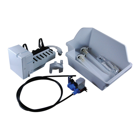
UK-KIT=$ and UK-KIT-5 contain.
..
Slotted Hex-Head Screw
Adhesive-Backed Fasteners
Ice Bucket
ICE
MAKER
WARRANTY
VERIFICATION
Warranty Label
Water Line Clamp Water Line Clamp
(used only with
Instruction Sheet
F)
Use
&
Care
Instructions,
Installation
Instructions
and Warranty
6
PARTS LIST
I
USEWITHINSTRUCTIONSHEET
1.
WaterValveAssembly
2.
SlottedHex-HeadScrew
3. HoseClamp
4.
Adhesive-BackedFasteners
~ ~ ~~
5.
FillTube Extension
6.
lcemaker
7.
IceBucket
8.
WarrantyLabel
9.
Water LineClamp
10.
Water LineClamp
11.
UserInstructionandWarranty
X X
X
X
X
X
X X X X
X
NO
X X
X
X X X
I I
I
I I
X X X X
X X
I I
I
I
I
X X
X
X X X
X
X X
X X
X
a'
1
OTHERPARTS
YOU
NEED...
Copper tubing, shut-off valve andfittings necessary UK-KIT5 also contains a bucket support for use as
tosupplywatertoyourrefrigeratorarenotincludeddescribed inInstruction
A.
inUK-KIT-4 or UK-KIT-5.
You can purchase a complete water supplykitfrom
your
GE
or Hotpoint dealer.
Recommendedwater supply kitsare Cat.
No.
WX8X2
(15
feet ofcopper tubing),WX8X3
(20
feet),
or WX8X4
(25
feet).
For
Instruction
B
only..
.youwill need a higher
bucket support anddifferentfill tube extension.
See page
12.
I
I
7
Installation
Instruction
Preparing
the
back
of
the
cabinet
Read each step thoroughly
before proceeding.
Tools needed:
Phillips-type screwdriver
Blade-type screwdriver
Sharp knife
Pliers
Step
1
Cautionm
unplug Refrigerator
To
eliminate
danger
of
electric
shock
during
installation,
you
refrigerator
must
unplug
from
the
yQ
its
electrical
outlet.
-\
Step
2
At
bottom of rear of refrigerator,
remove
2
screws holding
compresso~compartment cover
(if covered)andsave them for
reinstallation later. Bend cover back
for accesstothe compartment.
step
3
Locate femaleconnector plug
(A)
which is attached
to
cabinet
by awire tie. Removewire
tie
and discardit.
step
4
Push metal clamp
(9)
onto lower
flange ofcabinet backdirectly in
linewith water valve as shown.
Check plastic water linenut on
bottomof water valve
to
be
sure
it
is handtight.
DO
NOT
USE
TOOLS.
Remove anddiscard tape from
female connector and plug onto
maleterminals on water valve
(1).
Eitherwire cango on either
terminal.
Re-installcompressor
compartment cover
so
plastic
water lineis directed
out
of
compartment and up back
of
refrigerator.Fittingon water valve
should extendthrough hole in
coveras shown.
Note: On some models, you may
have
to
usescissors
to
cut the
compressor compartment cover
just
enough
to
allowthe water
valve inlet
to
stick
out
so
the
copper water line can be
connected
to
it
later.
I
(c) Fastenwater valve
to
cabinet
edge hole
(X)
usingslotted hex-
head screw
(2)
from kit. DONOT
DRILL
ANY ADDITIONAL
HOLES.
Step
5
On modelsthat have condenser
tubing on back
of
cabinet, insert
the plastic water line between
tubing and backof cabinet.
Step
6
Remove small plastic cap
(B)
from bottomof fill tube inlet
locatedin upper right rear corner
of refrigerator.Squeeze ends of
hoseclamp
(3)
from kit with
pliersand slide clamp over fill
tube inlet. While still squeezing
clamp, insert plastic water line
into inlet as far as
it
will
go
(approximately
1").
Then slide
clamp downward
to
capture
plasticwater line inplace.
Make sure fill tube inlet is
aimed down as shown below.
Step
7
Fastenplastic water line
to
back
e
of cabinetwith adhesive-backed
fasteners
(4),
spacing fasteners
as shown
to
take up slack inline.
1
1
8
(continued
on
page
70)
Installation
Instruction
Preparing the
back
of
the
cabinet
Read each step thoroughly
before proceeding.
Tools
needed:
Phillips-type screwdriver
Blade-type screwdriver
1/4"
nutdriver
Sharp knife
Pliers
Step
1
Caution.
Unplug Refrigerator
To
eliminate
danger
of
electric
shock
y
0
during installation,
you
must
unplug
the
1
refrigerator
from
its
electrical outlet.
Step
2
At bottom
of
rear of refrigerator,
remove
2
screwsholding
compressor compartment cover
and save them for reinstallation
later. Bend cover backfor access
to
the compartment.
,
?f
Remove
step
3
(a) Locate femaleconnector
plug
(C)
which is attached
to
cabinetby ametal clip. Remove
clip by removingscrew. Save
screw for mounting the water
valve later.Discardclip.
(b) Plug femaleconnector ontc
male terminals on water valve
(1).
Eitherwire can
go
on eithe
terminal.
I
,
(c) Fastenwater valve
to
cabinet
edge hole
(X)
usingslotted hex-
head screwthat you removedin
Step
3
(a).
DONOT DRILLANY
ADDITIONAL HOLES.
I
(d) Check plastic water linenuton
bottomof water
vah
to
be
sure
it
ishand tight.
W
NOT
USE
TOOLS.
Put
compressor compartment
coverback inplace
so
plastic
.
water line isdlrected out
of
the
top
of
the Compartment. Replace
screw
(A),
removedinStep
2.
Note:
On some models, you may
have
to
usescissors to cut the
compressor compartment cover
just enoughto allow the water
valve inlet
to
stick
out
so
the
copperwater linecan be
connected
to
it
later.
step
4
step
5
Attach waterline clamp
(10)
from
kit
to
refrigeratorfor safekeeping
untilyou connect the house
water line
to
the icemakerwater
valve (see page
17).
Drive screw
(E),
removedinStep
2,
into
cabinetedgethrough clamp and
hole incompressor cover.
Before the icemakeris operated,
the clamp must attach the copper
water line
to
the refrigerator
to
helpavoid unduewear on the
tubing that might cause leaks.
Step
6
Remove small plastic cap
(D)
from bottom
of
fill tube
inlet
locatedinupper right rearcomer
of refrigerator.Squeeze ends of
hoseclamp
(3)
from kit with
pliersand slide clamp overfill
tube inlet. While still squeezing
clamp, insert plastic water line
into inlet as far as
it
will go
(approximately
1").
Then slide
clamp downward
to
capture
plasticwater line inplace.
Make surefill tube inlet is
aimed down as shown below.
Step
7
Fasten plastic water line to back
of cabinetwith adhesive-backed
fasteners
(4),
spacingfasteners
as shown
to
take up slack in line.
W
Adhesive-backedfasteners
for plasticwater line
(continued
next
page/
9
Remove
and discard existing ice service.
Follow instructions inappropriateStep
8A
below.
Step 8A
Remove Ice traytunnel.
step%*
Remove ice traytunnel.
Disengage ice tunnel side and bot- Remove two screws
(C)
andsave
tom from retaining hooks. Lower
tun-
them for installation oficemaker.
ne1 untilsideis clear offreezer shelf Liftice tray tunnel
off
plastic hook
and remove
it
from freezer. Discard
(0)
and discard
it.
ice tunnel.
Step 8A
1
Remove ice tray shelf.
Lift ice tray shelf up
to
disengage
from tabs on cabinet wall and pull
it
forward as shown.
Tilt ice tray shelf and remove
it.
Discard shelf.
Reposition
freezer shelf.
Step 8A
Remove Ice traytunnel.
As
you
lift
tab on left side intunnel
with blade
of
screwdriver, pull tunnel
forward and
out.
Discard icetunnel.
Removeice trayshelf.
Pull
ice tray shelf
to
disengage
pins
from
holes
on
cabinet wall.
Tilt icetray shelf and remove
it.
Discard shelf.
c
Follow
instructions inappropriateStep
8B
below.
Step
88 Step 86 Step 8B
Applicable to models with
a
partial- Applicable to models witha full-width Applicable
to
models with a partial-
width shelf suspended from freezer shelf and alternate shelf locations. width shelf resting
on
freezerfloor.
width shelf. Relocate
shelf
against left wall
(under
icemaker mounting area).
Remove shelf
to
provide working
roan
during icemaker kit installation.
top, or
to
models with a stepped
full-
Reposition shelf at lowest level,
To
reposition the 2-piece shelf
supports:
Slide part
(E)
up off base
t
10
Inside
freezer compartment
’0
Step
9
Remove screw
(A)
that holds electri-
cal plugcover inplace. Discardscrew
and cover.
Step
10
Remove plastic insert
(B)
fromair
duct and discard it.
Loosentwoicemakermountina
Step
11
Cut the fill tubeextension
(5)tO
then
length with a sharp knife or single
edge razor blade andslideiton the fill
tube against thestop.
Step
12
Place icemaker in freezer compan-
ment as shown.Inserticemaker power
cord plug
(D)
into socket
on
sidewall,
makingsureprongsarematched
to
corresponding holes
and plug is firmly
seated in
socket.
Step
14
The icemakershould feel
secure
when
you
lift
the icemaker feeler arm
(F)
to
the
“OFF”
(up)position. Leave
it
there
until the refrigerator is connected
to
the water
SUDDIY
to
prevent Dremature
operation.
Step
13
Lifticemaker andpositionrear open-
ing infill cup
(E)
over fill tube ex-
tension
(5).
Hang icemaker on two
screws (C).
Make sure:
electrical plug
is
still firmly in
socket.
fill
tubeextension
(5)
is still in fill
cup opening-check rear
of
refriger-
ator
to
makesure fill tubehasnot
been pushed
out
of
the back
of
the
refrigerator.
icemakermounting screws are lo-
cated inuppermostposition
of
mount-
ing slots.
ING
SCREWSSECURELY
THENTIGHTENICEMAKERMOUNT-
Step
15
Replacefreezer shelf. Move bucket
support and ice bucket
(7)
into place
directlyunderthe icemaker.See
illustrationbelow.
NOTE: Check again
to
make sure the
icemaker power cord plug is fully in-
serted Into
its
socket
withprongs
matched
to
corresponding holes.
Checkagaintomake
sure
the
ice
maker
feeler
arm
(F)
Is In the
“OFF”
(UP)
PWRh.
Step
16
Alabel
(8)
isprovidedinthe
kit
torecord
the dateof installationforwarranty
purposes. Applyit
to
the back
of
the
refrigerator.
Step
17
The
warranty
for
the lcemaker
is
printed
on
thebackpage
of
thisbooklet. Keep
thisbookletwith
your
RetrigeratorUse
&
Care
book.
The icemakerinstallation
is
now
complete.Refer
to
water line hook-up instructions
on the back
of
therefrigerator
for
connection
to
home water supply.After water line
installation iscompleted, lower icemaker feeler arm
to
the
“ON”
(down)position.
The icemaking cvcle will not begin
unt/l
the icemakerand freerer compartment
reach operating temperature, then icemaking
will
begin automat/callly.
11
Installation
Instruction Insidefreezercompartment
MODELS THAT CALL FORTHIS
INSTRUCTION SHEET NEED
A
HIGHER BUCKET SUPPORT AND
DIFFERENT FILL TUBE THAN
IS
PROVIDED INTHIS KIT. THIS
HIGHER SUPPORT CAN ONLY
BE USED ON MODELS WITH
INSTRUCTION
6.
Obtainthis
new
support anda
fill
tube
extensionat nochargeby requesting
Pub.
No.
2-1003
fromGeneral
ElectricPublications,
c/o
Dri-View
Manufacturing
Co.,
4706
Allrnond
Ave., Louisville,
KY
40209.
Step
9
Removescrew
(A)
that holdselectri-
cal plug cover in place. Discardscrew
and cover.
Loosentwoscrews(C)amroxi-
mately
1/2”.
DO
NOT
REMOVE
THE
SCREWS.
Step
10
Take the
fill
tubeextension
(5)
fromthe
supplementarykit
2-1003
that you got
bv mail and slide it onto the fill tube
Gainstthe stop.
r
1
I
Step
11
Place icemaker in freezer compart-
ment as shown.Inserticemakerpower
cord plug
(D)
into socket on side Wall,
making sure prongsare matched to
corresponding holes and plug isfirmly
seatedinsocket. When inserted,
power cord plug should
fit
flushto
freezer wall.
Step
12
Lifticemaker andpositionrear open-
ing in fill cup
(E)
over fill tube exten-
sion
(5).
Hagicemaker
on
two
screws
(C).
Make sure:
electricalplug isstillfirmlyin
socket.
fill tube extension
(5)
is
still in
fill
cup opening-check rear of refriger-
atorto make sure
fill
tubehasnot
been pushed out of the back of the
refrigerator.
icemaker mounting screws are
lo-
cated
in
uppermost position of mount-
ing slots.
THENTIGHTENICEMAKERMOUNT-
INGSCREWSSECURELY.
1
Step 13
The icemakershouldfeel securewhen
you
lift
the icemaker feeler arm
(F)
to
the
“OFF”
(up)position. Leave
it
there
until the refrigerator is connected to
the water supply to prevent premature
operation.
12
icemaker
will
operate
Step
14
Step
15
A
label
(8)
isprovided
in
the
kit
to
record
the date of installationfor
warranty
purposes. Apply
it
to
the back of
the
refrigerator.
Step
16
The warranty
for
thelcemaker
is
printed
on
the back page
of
thisbook-
let. Keep thisbookletwith
your
Refrigerator Use
&
Carebook.
The icemakerinstallation
is
now
com
Dlete. Refer
to
water
line
hook-up
NOTE:
Check again
to
make sure
the
icemaker power cord plug is fully in-
serted
into
its
socket
with
Icemaking
cycle
will
not
begin
until
matchedto correspondingholes.
icemaker and freezer compartment
reach
ooeratinotemoerature.then
Checkagain
to
makesuretheice-
icemaking
begin
automatic
IJV.
maker feeler arm
(F)
is inthe
“OFF”
(up) position.
3
.
-r-
~~
Installation
Instruction
Insidefreezercompartment
Step
9
Remove screw
(A)
that holds elec-
tricalplug cover inplace.Discard
screw and cover.
Remove lightshield insert
(B)
and
discard
it.
*Loosentwoscrews
(C)
approxi-
mately
1
/2'.'
DO
NOT REMOVE THESE
SCREWS.
r
I
H
removed
Step
10
Cut the filltubeextension
(5)
totheB
length with a sharp knife or single-
edge razor blade and slide
it
onto the
fill tube against the stop.
Step
11
Place icemaker in freezer compart-
ment as shown.Insert icemakerpower
cord plug
(0)
into socketon side wall,
making sure prongs are matched to
corresponding holes and
plug
is
firmly
seatedinsocket.
I
I
1
Step
12
Lifticemakerand position rear open-
ing in fill cup
(E)
over fill tubeex-
tension
(5).
Hang icemaker on two
screws
(Cy
Make sure:
electrical
plug
is
still
firmly
in
socket.
fill
tube extension
(5)
is still in
fill
cup opening-check rearof refriger-
ator to make sure fill tube has not
been pushed out of the back of the
refrigerator.
icemaker mounting screws are
10-
cated inuppermostposition of mount-
ing slots.
INGSCREWSSECURELY
THENTIGHTENICEMAKERMOUNT-
/
Step
13
The icemakershould feel securewhen
you lift the icemaker feeler arm (F) to
the "OFF" (up)position. Leave
it
there
until the refrigerator is connected to
the water supply
to
prevent premature
operation.
Step
14
Put ice bucket
(7)
into place directly
under icemaker (to the
left
and all the
way
to
the rear of the shelf under
icemaker).
NOTE: Check again to
make sure the
icemakerpowercordplug
is
fully
in-
serted
into
its socket
with prongs
matchedto corresponding holes.
Checkagain to make sure icemaker
feelerarm(F) is in"OFF"(up) position,
Step
15
Alabel
(8)
isprovidedinthekittorecord
the date
of
installation for warranty
purposes. Apply it tothe back of the
refrigerator.
Step
16
The warrantyfor the icemaker
is
printed
on
thebackpage
of
this
book-
let. Keep this booklet with
your
Refrigerator Use&Carebook.
The icemaker installation isnow com-
plete.Refertowaterlinehook-up
instructionson the back of the refrig-
erator for connection to homewater
supply. After water line installation is
completed, lower icemaker feeler arm
to the "ON" (down)position.
lcemakingcyclewillnotbeginuntil
icemaker and freezer compartment
reach operating temperature, then
icemaking will begin automatically.
\
,
bucket
13
L
Installation
Instruction
Insidefreezercompartment
~~~~~~~
Step
9
Remove and discardelectricplug
cover and mounting screw
(A).
I
II
I
Cover
I
I
Step
10
Remove and discard plate
(B)
from
front of air duct.
Step
11
Loosentwoscrews
(c).
Replace
them if youremoved them when tak-
ing out the ice tray tunnel.
Screws should extend approximately
1/2”
out
from freezer wall.
Step
12
Cut the
fill
tubeextension
(5)
tothem
length with a sharp knife or single-
edge razor bladeand slide
it
onto the
fill tube against the stop.
Step
13
Place icemaker on relocated shelf in
freezer compartment as shown. Insert
icemaker power cordplug
(D)
into
socket on sidewall,makingsure
prongs are matched to COrreSpOnding
holes and
plug is
firmly
seated
in
socket.
Step
14
Lifticemakerandposition rear open-
ing
in
fillcup(E)overfilltubeextension
(5).
Hangicemakeron twoscrews
(C).
Make sure:
electrical plug
is
still
firmly
in
socket.
fill
tube extension
(5)
is still in fill
cup opening-check rearof refriger-
ator to make sure fill tube has not
been pushed out of the back of the
refrigerator.
icemaker mounting screws are
10-
cated in uppermost position of mount-
ing slots.
INGSCREWSSECURELY
THENTIGHTENICEMAKERMOUNT-
Step
15
The icemakershouldfeelsecurewhen
you lift the icemaker feeler arm
(F)
to
the
“OFF”
(up)position. Leave
it
there
until the refrigerator is connected to
the water supply to preventpremature
operation.
6-
Step
16
Moveicebucket
(7)
into place directty
undericemaker. Seeillustrationbelow.
NOTE:
Checkagain to
make
sure
the
icemakerpowercord plug
is
fully in-
serted into its socket
withprongs
matched to correspondingholes.
Check again to make surethe ice-
maker feeler arm
(F)
is
in
TIFF
(up) position.
Step
17
A label
(8)
is
provided in the
kit
to
recordthe date
of
installation for
war-
rantypurposes.Apply
it
to
the back
of
the refrigerator.
Step 18
The warrantyfor the icemakeris
printedon
the
backpage
of
thisbook-
let. Keep this booklet with your
RefrigeratorUse
&
Care book.
The icemakerinstallation isnow com
plete. Refer to waterlinehook-up
instructions on the back of the ref“-
eratorfor connection to home
4
supply. After water line installation
I-
completed, lower icemaker feeler arm
to
the
“ON”
(down)position.
lcemakingcycle will
not
beginuntil
icemaker and freezer compartment
reachoperating temperature, then
icemaking will begin automatically.
i
14
Step
9
Remove anddiscardelectricplug
cover and mounting screw
(A)
Step
12
Removeand discard white plug from
upper left corner of freezer wall.
removed
Cover
Step
10
If
grille
(E)
is not inplace
so
itslouvers
direct air
to
the left, turn
it
as follows:
Removescrew
(E,)
whichholds
grille
(8).
L
I
Remove grille
(B),
rotate
it
90°
counterclockwise, and reinstall
it
as
shownbelow.
Replace screw and tighten
Step
11
Loosen screws
(C)
butdo not screw
them all the way
out.
Screws should
extend approximately
1/2”
out
from
freezer wall.
Cutthe fill tubeextension
(5)
to the
SHORT length
if
your refrigerator
is
22.0
or
22.5
cubic feet (use a
sharp knife or single-edge razor
’
blade.) Otherwise use the
H
long
length. Slidethe extension onto
the fill tube against the stop.
Step
13
Placeicemaker on shelfinfreezer
compartment as shown.Insertice-
maker powercord plug
(D)
intosocket
on side wall, making sure prongsare
matched to corresponding holes and
plug is firmlyseated in socket.
L
Step
14
Lift icemaker and position rear
opening in
fill
cup
(E)
over fill tube
extension
(5).
Hangicemakeron two
screws
(C).
Make sure:
electricalplug isstillfirmly
in,
socket.
fill tube extension
(5)
is still in fill
cup opening-check rearof refriger-
ator to makesure
fill
tube has not
been pushed
out
of the back of the
refrigerator.
icemaker mounting screws are
10-
cated inuppermostposition of mount-
ing
slots.
INGSCREWSSECURELY.
THENTIGHTENICEMAKERMOUNT-
Step 15
The icemakershould feel securewhen
you lift the icemaker feeler arm
(F)
to
the
“OFF”
(up)position. Leave
it
there
until the refrigerator is connected to
the water supply
to
prevent premature
operation.
I
i
1
Step
16
Moveice bucket
(7)
intoplaceonshelf
directly under icemaker.
NOTE: Check again
to
make sure the
icemaker power cord plug is fully
in-
sertedintoits socket with prongs
matched
to
correspondingholes.
Check again to make sure icemaker
feelerarm
(F)
is in
“OFF”
(up)
position.
Step
17
A
label
(8)
isprovidedinthekitto record
the
date of installation for warranty
purposes. Apply
it
to the back of the
refrigerator.
Step 18
Thewarranty for theicemakeris
printed
on
the backpageofthis book-
let. Keep this booklet with
your
Refrigerator
Use
&
Care book.
The icemaker installation isnow com-
plete.Refer
to
water
line
hook-up
instructions on the back of the refrig-
erator for connection to homewater
supply. After water line installation is
completed, lower icemakerfeeler arm
to the “ON” (down)position.
lcemakingcyclewill notbegin until
icemaker and freezer compartment
reachoperatingtemperature,then
icemaking will begin automatically.
15
Installation
Instruction
Insidefreezercompartment
Step
9
Removeelectric plugcover by
inserting standard screwdriver
bladein
slot
at bottom of cover
and applying pressureupwards
while prying coveraway from
freezer wall. Discardcover.
Step
10
Loosen screws
(E)
but do not
screw them all the way
out.
Screws should extend
approximately
1/2”
out
from
freezer wall.
step
11
(a) Removeand discard white
plugfrom upper
left
corner of
freezer wall.
(b) Cut the fill tube extension
(5)
to
the
“F”
length. (Use a sharp
knifeor single-edgerator blade.)
Step
12
Remove icemakerpowercord
from clip. Hold icemaker in
freezer compartment as shown.
Insert icemakerpower cord plug
(F)
into socket on rear wall,
makingsure prongs are matched
to
corresponding holes and plug
is firmlyseated
in
socket.
Step
13
Lift icemakerand position rear
openingin fillcup
(G)
over fill
tube extension
(5).
Hang
icemakeron two screws
(E).
Make sure:
electrical plug is still firmiy
in
socket.
filltube extension
(5)
is stillin
fill cup opening-check rear of
refrigerator
to
make surefilltube
has not beenpushed
out
of the
back ofthe refrigerator.
icemakermounting screws are
locatedinuppermost position of
mounting
slots.
THEN TIGHTEN ICEMAKER
MOUNTING SCREWS SECURELY.
Step
14
The icemakershould feel secure
when you liftthe icemakerfeeler
arm
(H)
to
the
‘‘OFF’’
(up)
position. Leave
it
there untilthe
refrigeratoris connected
to
the
water supply
to
prevent
premature operation.
icemaker
will
operate
16
step
15
Position freezer shelffor icemaking
and moveice bucket
(7)
into
placeon shelf undericemakec
Straighttwo-position shelf
should be inlowerposition. Step
shelf‘s lowerstep should be
under icemaker. Cantilever
shelf‘s top lugs should be
in
6th
slots upfrom bottomof track.
NOTE: Check again
to
make
sure
the icemaker power cordis
fully inserted into itssocket
with prongs matched
to
corresponding holes.
Check again
to
makesure
icemakerfeeler arm
(H)
is
in
“OFF”
(up) position.
Step
16
A
label
(8)
is providedinthe kit
to
recordthe date
of
installation
for warranty purposes.Apply
it
to
the back ofthe refrigerator.
Step
17
The warranty for the icemaker
is printedon the back page of
this booklet. Keepthis booklet
with
your
Refrigerator
Use
&
Care Book.
The icemakerinstallation isnow
complete. Refer
to
water line
hookupinstructions on the back
of the refrigerator for connection
to
homewater supply.After
water line installation is
completed, lower icemakerfeeler
arm
to
the “ON” (down) position.
lcemaking cyclewill not be
untilicemakerand freezer
9,
compartment reach operating
temperature, then icemaking
willbegin automatically.
Water Line
fi
Installation Instruction
If
you
useyour refrigerator before
connecting the water
line,
make sure the
icemaker feeler arm is kept in the
“OFF”
position.
CAUTION:
When using any electrical device (such
as
a
power drill)duringinstallation, besure thedevice
is
insulated orwired in
a
manner to prevent the
hazard of electric shock.
All installations must bein accordance with
localplumbingcode requirements.
WARRANTY INFORMATION
Thiswaterline installation
is
notwarranted
by the refrigerator or icemaker manufacturer.
Followthese instructionscarefullyto
minimizetherisk ofexpensivewater
damage.
G’
I
WHAT YOU WILL NEED
A
cold watersupplyisrequired for
automaticicemakeroperation.
Water
pressure must be between
20
and
120
p.s.i.
Coppertubing,
1/4”
O.D.,
should be usedto
connectthe refrigerator to the watersupply.
Do
not use plastictubingorplastic fittings
because theconnection betweenthe water supply
and the refrigerator watervalve inlet
is
under
constant water pressure.Also, certain typesof
plastic tubingmay become brittlewith age and
crack, resultingin water leakage.
A
shutoff valve
should be connectedto thecold
water line. Theshutoff valve should have a water
inlet with a
minimuminsidediameterof
5/32”
at thepoint of connection to the COLD
WATER
LINE.
A
saddle typeshutoff valve
permitted by manylocal plumbing codes
is
shown
below.
Min.
5/32“
dia. opening
Check your local plumbing codesbefore choosing
this typeof valve. We recommend using the
saddle valve supplied with
GE
Water Supply Kits
WX8X2, WX8X3 and WX8X4.
17
TYPICAL PLUMBING INSTALLATION WITH WATER SUPPLY
KITS
WX8X2, WX8X3
and
WX8X4
121
INSTAUSHUTOFF VALVEON NEAREST
FREQUENTLY USEDDRINKINGWATER UNE.
a.
Choose a location forthe valve that iseasily
accessible. It is bestto connect intothe sideof a
vertical water pipe. When it
is
necessary to
connect into
a
horizontal water pipe, makethe
connection tothe top orside, rather thanatthe
bottom, toavoid drawing off any sediment from
the waterpipe.
b.
Drilla
1/4”
hole in the water pipe, using a
sharpbit. Remove any burrs resulting from
drilling the hole in the pipe.
c.
Tighten theclamp screws untilthe sealing
washer begins toswell.
,
ROUTE
COPPER
TUBINGBETWEEN
COLD
WATER
WEAND REFRIGERATOR.
Route the tubing througha hole drilledin the
floor (behindthe refrigerator or adjacent base
cabinet)asclose tothe wall aspossible. Besure
there
is
sufficient extra tubing (about
8
feet coiled
into
3
turns of about
10
inches diameter)to allow
the refrigerator tomove out fromthe wall after
installation.
~ ~~
-
141
CONNECT
COPPER
TUBING
TO
SHUTOFF VALVE.
Place thecompression nutand ferrule onto the
end of the tubing andconnect tothe shutoff valve.
Make sure the tubing isfully inserted into the
valve. Tightenthe compressionnut securely.
Q
:
151
CONNECT COPPERTUBING
TO
REFRIGERATOR.
Before makingconnectiontothe
refrigerator, besurerefrigerator power
cordisnotpluggedinto thewalloutlet.
a.
Turn wateron and flush outthe tubing, making
certain that allforeignmatter isremoved from the
line.
b.
Shut the wateroff after about one quart
of
water
has been flushed through thetubing.
NOTE:
Some localitiesmay have sand or other
foreign matter presentin the water supplyin such
quantities thatthey may, intime, collect in the
screen of thewater valve attached to the backof
the refrigerator and tendto reduce thewater flow
to the icemaker.Where such conditions exist,we
,
recommend that anadditional filter
or
strainer be
installed in the linenear therefrigerator. If a
screen type strainer is used,it should be
80
mesh
orfiner.
c.
Cut off theflared endof the copper tubing and
remove the flare nutfrom the tubing.
d.
Remove the plastic cap fromthe water valve
and plastictube assembly.
18
Water Line Installation Instruction
(continued)
<'.
'-2
.
e.
Connect coppertubing to the refrigerator
water valve by placing a
1/4"
compression nut
and ferrule onto the endof the tubingasshown.
f.
Insert the endof the copper tubing into the
water valve inlet as far
as
possible. While holding
the tubing, tighten thefitting.
g.
Fasten the copper tubingintothec1,amp
provided tohold it in
a
vertical position.
161
TURN ONWATER AND CHECK
AUJOINTS FOR LEAKS.
Tighten fittings
if
required to stop leaks.
171
PLUG REFRIGERATOR POWER CORDINTO
APPROPRIATE ELECTRICAL OUTLET.
SET THE
ICEMAKER
FEELER
ARM
TO
THE
ON
(DOWN) POSITION.
Theicemakerwill not beginto operate until it
reaches its operating temperatureof
15°F.
or
below. It will then begin operation automatically
if
the icemaker
is
in the
ON
position.
lol
MOVE
THE
REFRIGERATOR
BACK
TO
THE
WALL.
Arrange thecoil of copper tubing
so
that it does
not vibrate against the back
of
the refrigerator or
against thewall.
NOTE:
Thefirst few batches of cubes should be thrown
away,
so
that remaining impurities
in
the water
line will be flushed out.
19
YOUR AUTOMATIC ICEMAKER
Y
::>-
WARRANTY
Saveproof
of
original purchase date such as yoursalesslip or cancelled check to establish warranty period.
WHAT
IS
COVERED
FULL
ONE-YEARWARRANTY
Forone year from dateof original
purchase, wewill provide, free
of
charge, parts andservice labor
inyour hometo repair or replace
anypart
of
the automatic
icemaker
that failsbecause of a
manufacturingdefect.
This warrantyisextended to
theoriginal purchaserandany
succeeding owner for products
purchased for ordinary home use
inthe
48
mainlandstates, Hawaii
and Washington,D.C.
In
Alaskathe
warranty isthesame except thatit is
LIMITED because you must pay to
ship theproductto the serviceshop
or for the service technician’s travel
costs to your home.
All warranty servicewill beprovided
by our Factory Service Centers or
byour authorized Customer Care@
servicersduringnormal working
hours.
Look intheWhiteor Yellow Pages
of your telephone directory for
GENERAL ELECTRIC COMPANY,
GENERAL ELECTRIC FACTORY
HOTPOINT FACTORY SERVICE or
GENERAL ELECTRIC CUSTOMER
CARE@ SERVICE.
SERVICE, GENERAL ELECTRIC-
~
WHAT
1s
NOT
COVERED
Servicetrips toyourhometo
teach you how to usetheproduct.
Read your Use and Care material.
If
you then have any questions
about operatingtheproduct,
please contact your dealeror our
Consumer Affairsofficeat the
address below, orcall,tollfree:
GE AnswerCenteP
800.626.2000
consumerinformationservice
Improper installation.
If
you have aninstallationproblem,
contact your dealer or installer.
You areresponsiblefor providing
adequateelectrical,plumbingand
other connectingfacilities, including
thewater lineto the icemakerand the
water lineinstallation.
Replacementof house fuses or
resettingof circuitbreakers.
Failure of the product
if
itis used
for otherthan itsintended purpose
or used commercially.
Damage
to
product caused
byaccident, fire, floods or acts
of God.
WARRANlOR
IS
NOT
RESPONSIBLE
FOR
CONSEQUENTIAL DAMAGES.
Somestates donot allowtheexclusionor limitationof incidental or consequentialdamages,
so
theabovelimitationor exclusion
maynotapply to you. Thiswarranty givesyou specific legalrights,andyou may
also
haveother rights which vary from stateto state.
To knowwhat yourlegalrightsare inyour state,consult your local or stateconsumeraffairsoffice oryour state’sAttorneyGeneral.
Warrantor: General Electric Company
If
further help isneededconcerning this warranty, write:
Manager-Consumer Affairs, GE Appliances, Louisville,
KY
40225
I
Part
No.
162D1925P004
11-68
UK-KIT4
UK-KIT5

This manual suits for next models

1

Other GE Ice Maker manuals

GE OPAL NUGGET User manual

GE

GE OPAL NUGGET User manual

GE IM6 Operating instructions

GE

GE IM6 Operating instructions

GE Profile XPIOX3SCSS User manual

GE

GE Profile XPIOX3SCSS User manual

GE unc15 Operating instructions

GE

GE unc15 Operating instructions

GE OPAL01GEPKT User manual

GE

GE OPAL01GEPKT User manual

GE UCC15NP User manual

GE

GE UCC15NP User manual

GE Monogram Refrigerator Manual

GE

GE Monogram Refrigerator Manual

GE Monogram ZDI15 User manual

GE

GE Monogram ZDI15 User manual

GE Kit IM-5SS Operating instructions

GE

GE Kit IM-5SS Operating instructions

GE monogram ZDIC150 User manual

GE

GE monogram ZDIC150 User manual

GE GBS2OKB Operating instructions

GE

GE GBS2OKB Operating instructions

GE Monogram ZDI15CBB User guide

GE

GE Monogram ZDI15CBB User guide

GE Monogram ZDI15CWW User guide

GE

GE Monogram ZDI15CWW User guide

GE Profile XPIOX3SCBT User manual

GE

GE Profile XPIOX3SCBT User manual

GE MONOGRAM ZDIS15CSS User guide

GE

GE MONOGRAM ZDIS15CSS User guide

GE monogram ZDIC150 User manual

GE

GE monogram ZDIC150 User manual

GE OPAL 2.0 User manual

GE

GE OPAL 2.0 User manual

GE XPIO43SCSS User manual

GE

GE XPIO43SCSS User manual

GE IM-4A Operating instructions

GE

GE IM-4A Operating instructions

GE IM-5D Original instructions

GE

GE IM-5D Original instructions

GE monogram ZDIC150 User manual

GE

GE monogram ZDIC150 User manual

GE IM-4A Operating instructions

GE

GE IM-4A Operating instructions

GE UCC15NPRII Operating instructions

GE

GE UCC15NPRII Operating instructions

GE OPAL01GEPKT User manual

GE

GE OPAL01GEPKT User manual

Popular Ice Maker manuals by other brands

ibingo KC-300AS Product introduction

ibingo

ibingo KC-300AS Product introduction

Hoshizaki KM-40B How to replace

Hoshizaki

Hoshizaki KM-40B How to replace

BERG BC360N Service, installation, and instruction manual

BERG

BERG BC360N Service, installation, and instruction manual

U-Line Echelon BI-2115 Use and care guide

U-Line

U-Line Echelon BI-2115 Use and care guide

Hoshizaki IM-130BAB-21 Service manual

Hoshizaki

Hoshizaki IM-130BAB-21 Service manual

Carnival King 382IBS250 user manual

Carnival King

Carnival King 382IBS250 user manual

ITV SPIKA Series Service manual

ITV

ITV SPIKA Series Service manual

Hoshizaki KM-1300SAH instruction manual

Hoshizaki

Hoshizaki KM-1300SAH instruction manual

Hoshizaki KM-470AJ instruction manual

Hoshizaki

Hoshizaki KM-470AJ instruction manual

Manitowoc S3000 Installation, operation and maintenance manual

Manitowoc

Manitowoc S3000 Installation, operation and maintenance manual

EdgeStar 01M450SS owner's manual

EdgeStar

EdgeStar 01M450SS owner's manual

Hoshizaki F-801MAH instruction manual

Hoshizaki

Hoshizaki F-801MAH instruction manual

Avallon AIMG151GPRI owner's manual

Avallon

Avallon AIMG151GPRI owner's manual

Morris DIM-20220 user manual

Morris

Morris DIM-20220 user manual

KitchenAid KUIS15NRTW - 25 lbs. Capacity Ice Maker manual

KitchenAid

KitchenAid KUIS15NRTW - 25 lbs. Capacity Ice Maker manual

Cornelius Enduro-300 IntelliCarb Operator's manual

Cornelius

Cornelius Enduro-300 IntelliCarb Operator's manual

Cornelius Nordic CCU0220 Brochure & specs

Cornelius

Cornelius Nordic CCU0220 Brochure & specs

Freezimer HIM-35B user manual

Freezimer

Freezimer HIM-35B user manual

manuals.online logo
manuals.online logoBrands
  • About & Mission
  • Contact us
  • Privacy Policy
  • Terms and Conditions

Copyright 2025 Manuals.Online. All Rights Reserved.