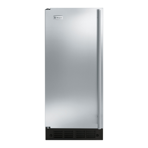
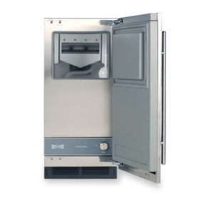
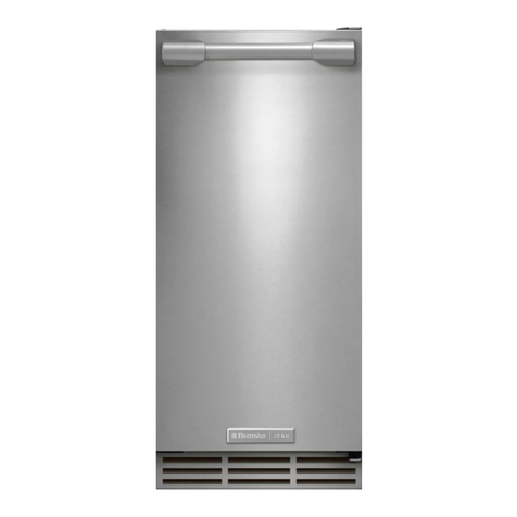
GE UCC15NPRII Operating instructions

Write the model and serial
numbers here:
Model #_________________
Serial # _________________
Find these numbers on a label
on the top inner case liner of the
unit toward the front.
GE is a trademark of the General Electric Company. Manufactured under trademark license.
OWNER’S MANUAL
AND INSTALLATION
INSTRUCTIONS
ICE MACHINE
49-1000640 Rev. 3 11-22 GEA
UCC15NP
ENGLISH/FRANÇAIS/
ESPAÑOL
SAFETY INFORMATION .........3
USING THE ICE MACHINE
Packaging ............................6
Controls ..............................6
Features ..............................8
Starting the Ice Machine ................8
INSTALLATION INSTRUCTIONS
Grounding the Ice Machine..............9
Before You Begin ......................9
Location and Preparation ...............9
Advance Planning .................... 11
Dimensions ..........................12
Door Swing ..........................13
Door Panel...........................15
Handle Reversing Instructions ..........18
Plumbing ............................18
Toe Kick Location ....................19
Drain Pump Kit UPK4 Accessory
Installation ....................... 20
CARE AND CLEANING ......... 24
TROUBLESHOOTING TIPS......27
LIMITED WARRANTY ...........28
ACCESSORIES .................. 29
CONSUMER SUPPORT ......... 30

249-1000640 Rev. 3
THANK YOU FOR MAKING GE APPLIANCES A PART OF YOUR HOME.
Whether you grew up with GE Appliances, or this is your first, we’re happy to have you in the family.
We take pride in the craftsmanship, innovation and design that goes into every GEAppliances
product, and we think you will too. Among other things, registration of your appliance ensures that we
can deliver important product information and warranty details when you need them.
Register your GE appliance now online. Helpful websites and phone numbers are available in the
Consumer Support section of this Owner’s Manual. You may also mail in the pre-printed registration
card included in the packing material.

49-1000640 Rev. 3 3
SAFETY INFORMATION
READ AND SAVE THESE INSTRUCTIONS
IMPORTANT SAFETY INFORMATION
READ ALL INSTRUCTIONS BEFORE USING THE APPLIANCE
INSTALLATION
WARNING EXPLOSION HAZARD
Keep flammable materials and vapors, such as gasoline, away from appliance. Failure to do so can result in fire,
explosion, or death.
WARNING To reduce the risk of fire, explosion, electric shock, or injury when using your ice
machine, follow these basic safety precautions:
Ŷ 7KLV,FHPDFKLQHPXVWEHSURSHUO\LQVWDOOHG
DQGORFDWHGLQDFFRUGDQFHZLWKWKH,QVWDOODWLRQ
,QVWUXFWLRQVEHIRUHLWLVXVHG
Ŷ 8QSOXJWKH,FHPDFKLQHEHIRUHPDNLQJUHSDLUV
replacing a light bulb, or cleaning.
NOTE:3RZHUWRWKH,FHPDFKLQHFDQQRWEH
disconnected by any setting on the control panel.
NOTE: Repairs must be performed by a qualified
Service Professional.
Ŷ 5HSODFHDOOSDUWVDQGSDQHOVEHIRUHRSHUDWLQJ
Ŷ 'RQRWXVHDQH[WHQVLRQFRUG
Ŷ 'RQRWVWRUHRUXVHJDVROLQHRURWKHUIODPPDEOH
vapors and liquids in the vicinity of this or any other
appliance.
Ŷ 'RQRWVWRUHH[SORVLYHVXEVWDQFHVVXFKDVDHURVRO
cans with a flammable propellant in this appliance.
Ŷ 7RSUHYHQWVXIIRFDWLRQDQGHQWUDSPHQWKD]DUGVWR
FKLOGUHQUHPRYHWKH,FHPDFKLQHGRRUIURPDQ\,FH
machine before disposing of it or discontinuing its
use.
Ŷ 7RDYRLGVHULRXVLQMXU\RUGHDWKFKLOGUHQVKRXOGQRW
stand on, or play in or with the appliance.
Ŷ &KLOGUHQDQGSHUVRQVZLWKUHGXFHGSK\VLFDOVHQVRU\
or mental capabilities or lack of experience and
knowledge can use this appliance only if they are
supervised or have been given instructions on safe
XVHDQGXQGHUVWDQGWKHKD]DUGVLQYROYHG
Ŷ 7KLVDSSOLDQFHLVLQWHQGHGWREHXVHGLQKRXVHKROG
and similar applications such as: staff kitchen areas
in shops, offices and other working environments;
farm houses; by clients in hotels, motels, bed
& breakfast and other residential environments;
catering and similar non-retail applications.
Ŷ &RQQHFWWRSRWDEOHZDWHUVXSSO\RQO\$FROGZDWHU
supply is required for automatic icemaker operation.
The water pressure must be between 30 and 120 psi
(207-827 kilopascals).
Ŷ 'RQRWDSSO\KDUVKFOHDQHUVWRWKH,FHPDFKLQH
Certain cleaners will damage plastic which may
cause parts such as the door or door handles to
detach unexpectedly. See the Care and Cleaning
section for detailed instructions.
CAUTION 7RUHGXFHWKHULVNRILQMXU\ZKHQXVLQJ\RXU,FHPDFKLQHIROORZWKHVHEDVLFVDIHW\
precautions.
Ŷ .HHSILQJHUVRXWRIWKH³SLQFKSRLQW´DUHDV
clearances between the doors and between the
doors and cabinet are necessarily small. Be careful
closing doors when children are in the area.
Ŷ 'RQRWWRXFKWKHFROGVXUIDFHVLQWKHLFH
compartment.
Ŷ $YRLGFRQWDFWZLWKPRYLQJSDUWVRIWKHLFHPDNHU

449-1000640 Rev. 3
Do not, under any circumstances, cut or remove the third (ground) prong from the power cord. For
personal safety, this appliance must be properly grounded.
The power cord of this appliance is equipped with a
3-prong (grounding) plug which mates with a standard
SURQJJURXQGLQJZDOORXWOHWWRPLQLPL]HWKH
SRVVLELOLW\RIHOHFWULFVKRFNKD]DUGIURPWKLVDSSOLDQFH
Have the wall outlet and circuit checked by a qualified
electrician to make sure the outlet is properly
grounded.
Where a standard 2-prong wall outlet is encountered, it
is your personal responsibility and obligation to have it
replaced with a properly grounded 3-prong wall outlet.
The ice maker should always be plugged into its own
YROW+]DPSFLUFXLW7KLVSURYLGHVWKHEHVW
performance and also prevents overloading house
ZLULQJFLUFXLWVZKLFKFRXOGFDXVHDILUHKD]DUGIURP
overheated wires.
Never unplug your ice maker by pulling on the power
cord. Always grip plug firmly and pull straight out from
the outlet.
Repair or replace immediately all power cords that
KDYHEHFRPHIUD\HGRURWKHUZLVHGDPDJHG'RQRW
use a cord that shows cracks or abrasion damage
along its length or at either end.
When moving the ice maker, be careful not to roll over
or damage the power cord.
CONNECTING ELECTRICITY
WARNING ELECTRICAL SHOCK HAZARD
Plug into a grounded 3-prong outlet
'RQRWUHPRYHWKHJURXQGSURQJ
'RQRWXVHDQDGDSWHU
Failure to follow these instructions can result in death, fire, or electrical shock.
SAFETY INFORMATION
IMPORTANT SAFETY INFORMATION
READ ALL INSTRUCTIONS BEFORE USING THE APPLIANCE
READ AND SAVE THESE INSTRUCTIONS
WARNING FIRE OR EXPLOSION HAZARD Flammable Refrigerant
This appliance contains isobutane refrigerant,
also known as R600a, a natural gas with high
environmental compatibility. However, it is also
combustible. Adhere to the warnings below to
reduce the risk of injury or property damage.
1. When handling, installing and operating the
appliance, care should be taken to avoid damage to
the refrigerant tubing.
2. 6HUYLFHVKDOORQO\EHSHUIRUPHGE\DXWKRUL]HG
VHUYLFHSHUVRQQHO8VHRQO\PDQXIDFWXUHUDXWKRUL]HG
service parts.
3. 'LVSRVHRI,FHPDFKLQHLQDFFRUGDQFHZLWK)HGHUDO
and Local Regulations. Flammable refrigerant and
insulation material used require special disposal
procedures. Contact your local authorities for the
HQYLURQPHQWDOO\VDIHGLVSRVDORI\RXU,FHPDFKLQH
4. Keep ventilation openings in the appliance
enclosures or in the built-in structure clear of
obstruction.
5. 'RQRWXVHDQLFHSLFNPHWDORUVKDUSHGJHG
instrument to remove any frost or ice in the ice
maker compartment as it may puncture the liner and
then the flammable refrigerant tubing behind it.
6. 'RQRWXVHHOHFWULFDODSSOLDQFHVLQVLGHWKHIRRG
storage compartment of the appliance.
7.'RQRWXVHDQ\HOHFWULFDOGHYLFHIRUPHOWLQJRU
thawing any ice or frost in your icemaker.

49-1000640 Rev. 3
WARNING SUFFOCATION AND CHILD ENTRAPMENT HAZARD
Remove the door from the appliance prior to disposal. Failure to do so can result in child entrapment which can
lead to death or brain damage.
IMPORTANT: Child entrapment and suffocation are not
problems of the past. Junked or abandoned appliances
DUHVWLOOGDQJHURXVHYHQLIWKH\ZLOOVLWIRU³MXVWDIHZ
GD\V´,I\RXDUHJHWWLQJULGRI\RXUROGDSSOLDQFH
please follow the instructions below to help prevent
accidents.
Before You Throw Away Your Old Appliance:
ŶTake off the doors.
ŶLeave the internal components in place so that
children may not easily climb inside.
PROPER DISPOSAL OF YOUR OLD APPLIANCE
READ AND SAVE THESE INSTRUCTIONS
SAFETY INFORMATION
IMPORTANT SAFETY INFORMATION
READ ALL INSTRUCTIONS BEFORE USING THE APPLIANCE
REFRIGERANT AND FOAM DISPOSAL:
'LVSRVHRIRUUHF\FOHDSSOLDQFHLQDFFRUGDQFHZLWK)HGHUDODQG/RFDO5HJXODWLRQV)ODPPDEOHLQVXODWLRQPDWHULDO
used requires special disposal procedures. Contact your local authorities for the environmentally safe disposal or
recycling of your appliance.

649-1000640 Rev. 3
Remove Packaging
IMPORTANT:'RQRWUHPRYHDQ\SHUPDQHQW
instruction labels inside your ice machine or the Tech
Sheet that is fastened behind the kickplate.
Ŷ5HPRYHWDSHDQGDQ\ODEHOVIURP\RXULFHPDNHU
before using (except the model and serial number
label).
To remove any remaining tape or glue, rub the area
briskly with your thumb. Tape or glue residue can
also be easily removed by rubbing a small amount of
liquid dish soap over the adhesive with your fingers.
Wipe with warm water and dry.
Ŷ'RQRWXVHVKDUSLQVWUXPHQWVUXEELQJDOFRKRO
flammable fluids or abrasive cleaners to remove tape
or glue. These products can damage the surface of
\RXULFHPDNHU)RUPRUHLQIRUPDWLRQVHH,PSRUWDQW
6DIHW\,QVWUXFWLRQV
Door Alarm
An alert will sound when the door has been left open for
PLQXWHV7KHDOHUWVWRSVZKHQGRRULVFORVHG6QRR]H
the alert by pressing any button.
'LVDEOHWKHGRRUDODUPE\SUHVVLQJ³3RZHU´&OHDQDQG
³)LOWHU5HVHW´EXWWRQVDWWKHVDPHWLPH
Sabbath Mode
The Sabbath Mode was designed for use on the Jewish
Sabbath and Holidays. The icemaker will not make ice
GXULQJWKH6DEEDWKPRGH,I6DEEDWKPRGHLVHQWHUHG
while making ice, icemaker will complete current cycle
EHIRUHWXUQLQJRIIOHVVWKDQPLQXWHV,FHPDNLQJ
ZLOOVWDUWDJDLQDWWKHHQGRIWKH6DEEDWKPRGH,IWKH
icemaker is equipped with a drain pump, it will continue
to work as normal.
The icemaker will exit Sabbath mode automatically after
96 hours.
ON/OFF - To activate the Sabbath Mode, Press and
KROG³3RZHU´DQG³)LOWHU5HVHW´IRUVHFRQGV7RH[LW
6DEEDWK0RGH3UHVVDQG+ROG³3RZHU´DQG³)LOWHU
5HVHW´IRUVHFRQGV7KH0DNLQJ,FH7LPHWR&OHDQ
DQG5HSODFH)LOWHUOLJKWVZLOODOOWXUQRQWRLQGLFDWH
6DEEDWKPRGHLVDFWLYH
1. POWER3UHVVDQGKROGIRUVHFRQGVWRWXUQLFHPDNLQJRQ0DNLQJ,FH,QGLFDWRUZLOOWXUQRQ3UHVVDQGKROG
IRUVHFRQGVWRWXUQLFHPDNLQJRII,ILFHPDNHULVPDNLQJLFHZKHQWXUQHGRIIWKH0DNLQJ,FHLQGLFDWRU
will flash until the current icemaking cycle is complete prior to turning off. The icemaker will also drain
DQ\ZDWHULQWKHWDQNHYHU\WLPHLWLVWXUQHGRII,IGXULQJLFHPDNLQJ\RXQHHGWRWXUQRII\RXUSURGXFW
LPPHGLDWHO\SUHVVVDQGKROGWKH3RZHUEXWWRQIRUVHFRQGVDJDLQ
2. CLEAN - Press and hold for 3 seconds to start the cleaning process. (See Care and Cleaning)
3. FILTER RESET - Press after changing filter to reset filter timer. (See GSWF Water Filter)
4. WiFi - Press and hold Clean and Filter buttons at the same time. WiFi symbol will start blinking. (See Wifi section)
5. MAKING ICE ,QGLFDWRUZLOOEHRQZKHQXQLWLVZLWKLQLFHPDNLQJPRGH
6. TIME TO CLEAN ,QGLFDWRUZLOOWXUQRQDIWHUPRQWKVLQGLFDWLQJLWLVWLPHWRRUGHUFOHDQHU,QGLFDWRUZLOOIODVKDIWHU
6 months indicating it is time to clean the machine. (See Care and Cleaning)
7. Replace Filter ,QGLFDWRUZLOOLOOXPLQDWHZKHQLWLVWLPHWRRUGHUDILOWHU,QGLFDWRUZLOOIODVKZKHQLWLVWLPHWRUHSODFH
the filter. (See GSWF Water Filter)
Packaging
USING THE ICE MACHINE: Packaging/ Controls
1 2 3
4
56
7
Controls

49-1000640 Rev. 3 7
Regulatory Information
FCC/IC Compliance Statement:
7KLVGHYLFHFRPSOLHVZLWK3DUWRIWKH)&&5XOHV
Operation is subject to the following two conditions:
1. This device may not cause harmful interference, and
2. This device must accept any interference received,
including interference that may cause undesired
operation.
This equipment has been tested and found to comply
with the limits for a Class B digital device, pursuant to
3DUWRIWKH)&&5XOHV7KHVHOLPLWVDUHGHVLJQHG
to provide reasonable protection against harmful
interference in a residential installation. This equipment
generates, uses and can radiate radio frequency energy
and, if not installed and used in accordance with the
instructions, may cause harmful interference to radio
communications.
However, there is no guarantee that interference will
QRWRFFXULQDSDUWLFXODULQVWDOODWLRQ,IWKLVHTXLSPHQW
does cause harmful interference to radio or television
reception, which can be determined by turning the
equipment off and on, the user is encouraged to try to
correct the interference by one or more of the following
measures:
• Reorient or relocate the receiving antenna.
,QFUHDVHWKHVHSDUDWLRQEHWZHHQWKHHTXLSPHQWDQG
receiver.
• Connect the equipment into an outlet on a circuit
different from that to which the receiver is connected.
• Consult the dealer or an experienced radio/television
technician for help.
Labelling: Changes or modifications to this unit not
expressly approved by the manufacturer could void the
user’s authority to operate the equipment.
Appliance Communication
WiFi (for customers in the United States, its
territories, and Canada)
'RZQORDGWKH6PDUW+4DSS
• Available for iPhone from the Apple Store or from
link at GEAppliances.com.
• Available for Android from Google Play or from link
at GEAppliances.com.
Select Create Account on app.
• Enter information, and select Register. An e-mail will
be generated.
• When you receive the e-mail, select Verify Account.
6LJQLQZLWK\RXUFUHGHQWLDOVDQGVHOHFW$XWKRUL]HWR
allow the app to communicate with your icemaker.
Set up the app.
• Press the at the top of the screen.
&KRRVH*($SSOLDQFHV!5HIULJHUDWLRQ!8QGHU
&RXQWHU,FHPDNHU!
• The info button will show a picture of the touch
display on the appliance. Select OK.
• Select Next.
Press WiFi Connect on the control. Press and hold
Clean and Filter buttons at the same time The WiFi
symbol will start flashing on the display.
• Select Next in the app.
)LQGWKHSDVVZRUGRQWKH&RQQHFWHG$SSOLDQFH
,QIRUPDWLRQ/DEHOE\RSHQLQJWKH:DWHU)LOWHU$FFHVV
'RRUDWWKHERWWRPRIWKH,FH0DNHU
• Enter the password into the app.
&RQQHFWWRWKH,FHPDNHU¶V:L)L0RGXOHLQWKHSKRQH¶V
:L)LVHWWLQJVWKHQUHWXUQEDFNWRWKH6PDUW+4$SS
and select Next.
7KH:L)LZLOOKDYHWKHIRUPDW³*(B02'8/(B
;;;;´7KHPRGXOHQXPEHUFDQDOVREHIRXQGRQ
WKH&RQQHFWHG$SSOLDQFH,QIRUPDWLRQODEHOLQVLGHWKH
Filter Access cover below the ice storage bin.
• Connect to the home WiFi network and type in the
home WiFi password.
,IDOOFKHFNPDUNVDSSHDUDQGWKHXVHUJHWVDVFUHHQ
that says the device is connected, the device has
been successfully connected.
,IWKHDSSIDLOVWRFRQQHFWWKHDSSZLOOGLVSOD\WKH³2RSV
6RPHWKLQJ:HQW:URQJ´VFUHHQ7KHXVHUZLOOEHJLYHQ
possible reasons why connection failed and the option
to retry.
Controls
USING THE ICE MACHINE: Packaging/ Controls

849-1000640 Rev. 3
Starting the ice machine
,FHVFRRS
Light
Water filter
Kick Plate
&RQQHFWHG$SSOLDQFH,QIRUPDWLRQ/DEHO
Control panel
Water filter
access door
Initial Start Up
1. Turn on the water supply.
2. Switch on the electrical power.
3UHVVDQGKROG3RZHUIRUVHFRQGVWRVWDUWWKH
PDFKLQH7KH0DNLQJ,FHOLJKWZLOOWXUQRQ
4. Water will begin to flow into the unit. When the
reservoir is full, water will start to drain from the
machine. After a few minutes the compressor, water
pump and fan motor will begin to operate as the first
ice making cycle begins.
,QDSSUR[LPDWHO\PLQXWHVLFHZLOOIDOOLQWRWKHLFH
storage bin. The machine makes 24 cubes at a time.
,WLVQRUPDOIRUWKHILUVWEDWFKHVRILFHWRPHOWDVWKH
ELQFRROV,WZLOOWDNHKRXUVRIFRQWLQXRXVUXQ
time to fill the ice bin. When the ice bin is full, the ice
PDFKLQHZLOOVKXWRII,WZLOODXWRPDWLFDOO\UHVWDUWZKHQ
the ice level falls, either from use or normal meltage.
'LVFDUGWKHILUVWELQIXOORILFH
Features
USING THE ICE MACHINE: Features/ Starting the ice machine
This machine takes in room temperature air at the lower
right front and forces warm air out the lower left front.
Restricting the airflow or operating the machine in a hot
or cold environment will adversely affect the ability of the
ice machine to make ice.
When the door is opened, the control panel, ice making
area and ice storage bin are visible. The scoop is located
in a holder on the inside of the door.
This is a gravity drain model that must have a building
drain connection below the level of the drain tube at the
back of the cabinet. A pump can be installed, which can
force drain water up a maximum of 8 feet, allowing it
to be located where a gravity drain isn't available. See
Accessories on page 27 for more information on the
drain pump. Warm Air Out $LU,QWDNH

49-1000640 Rev. 3 9
GROUNDING THE ICE MACHINE
WARNING Electrical Shock Hazard.
Failure to follow these instructions can result in death,
fire, or electrical shock.
The power cord of this appliance is equipped with a
3-prong (grounding) plug which mates with a standard
SURQJJURXQGLQJZDOORXWOHWWRPLQLPL]HWKH
SRVVLELOLW\RIHOHFWULFVKRFNKD]DUGIURPWKLVDSSOLDQFH
Have the wall outlet and circuit checked by a qualified
electrician to make sure the outlet is properly
grounded.
Where a standard 2-prong wall outlet is encountered,
it is your personal responsibility and obligation to have
it replaced with a properly grounded 3-prong wall
outlet.
'212781'(5$1<&,5&8067$1&(6&8725
5(029(7+(7+,5'*5281'3521*)520
7+(32:(5&25'
'212786($1$'$37(53/8*72&211(&7
7+($33/,$1&(72$3521*287/(7
'212786($1(;7(16,21&25':,7+7+,6
$33/,$1&(
Questions? Call 800.GE.CARES (800.432.2737) or visit our Website at: GEAppliances.com
In Canada, call 1.800.561.3344 or visit our Website at: GEAppliances.ca
BEFORE YOU BEGIN
Read these instructions completely and carefully.
• IMPORTANT —Observe all governing codes
and ordinances. Save these instructions for local
inspector’s use.
• Note to Installer – Be sure to leave these
instructions with the Consumer.
• Note to Consumer – Keep these instructions for
future reference.
• Skill level – ,QVWDOODWLRQRIWKLVDSSOLDQFHUHTXLUHV
basic mechanical skills.
• Completion time – ,QVWDOODWLRQFDQYDU\
:DWHU/LQH,QVWDOODWLRQ
minutes
• Proper installation is the responsibility of the
installer.
• Product failure due to improper installation is not
covered under the Warranty.
ICE MACHINE LOCATION AND
PREPARATION
This ice machine is designed to be used indoors, in a
controlled environment.
,WLVPDGHXSRIWZRPDMRUV\VWHPVWKHLFHPDNLQJ
system and the ice storage system. The ice making
system makes ice when the ice level becomes low
and stops when it is full.
The ice storage system is an insulated chest
ZLWKDGUDLQDWWKHERWWRPIRUPHOWLQJLFH,WLVQRW
refrigerated, insuring that the bin contains fresh ice.
IMPORTANT: Never keep anything in the ice storage
bin that is not ice. Objects like wine or beer bottles are
not only unsanitary, but the labels can slip off and plug
up the drain.
IMPORTANT: Never allow the machine to operate
without regular cleaning. The machine will last longer
if it is kept clean. Regular cleaning should happen
twice per year. Some water conditions will dictate
even more frequent cleaning of the ice making
section, and some carpets or pets will dictate more
frequent cleaning of the condenser.
Specifications
The ice machine will operate adequately within the
limits, but functions best in temperatures between
60°F and 80°F.
0LQLPXPDLUWHPSHUDWXUH)&
• Maximum air temperature: 100°F (38°C)
0LQLPXPZDWHUWHPSHUDWXUH)&
• Maximum water temperature: 90°F. (32°C)
• Minimum water pressure: 30 psi (2.07 bar)
• Maximum water pressure: 120 psi (8.27 bar)
Electrical voltage limits:
See the Rating Plate inside the ice machine.
INSTALLATION INSTRUCTIONS
Installation
Instructions ICE MACHINE

10 49-1000640 Rev. 3
Installation Instructions
INSTALLATION INSTRUCTIONS
ICE MACHINE LOCATION AND PREPARATION (Cont.)
Utility and Operational Requirements
• This ice machine must be connected to a potable
water supply.
All water, including potable water supplied by
municipalities, contains some impurities or minerals.
Water absorbs impurities from the air as rain and/or
as it flows through the ground. Some of the impurities
are solid particles. These are known as suspended
solids, and a fine particle filter will remove them.
Other impurities are chemically bonded to the water
molecules and cannot be filtered out. These are
called dissolved solids.
,FHPDGHE\WKLVPDFKLQHZLOOKDYHDORZHUPLQHUDO
content than the water it was made from. This is due
WRWKHPHWKRGRIPDNLQJLFH3XUHUZDWHUZLOOIUHH]H
first in the ice making molds. The reason for this is
that anything dissolved in water lowers the water's
IUHH]LQJWHPSHUDWXUH7KLVFRQFHQWUDWHVPRVWRIWKH
impurities of the ice machine water reservoir where
they may form hard deposits known as scale. The
machine dilutes the concentration of minerals by
over-filling the reservoir during the harvest cycle (with
the excess water flowing down the drain). Water use
varies with air and water temperatures.
Some impurities will inevitably remain, and will stick
to the parts in the machine. This will cause malformed
ice cubes. Eventually, built up mineral scale can
shorten machine life.
To keep the machine operating properly, these
impurities or minerals will have to be regularly
GLVVROYHGE\DQDFLGFOHDQHU'LUHFWLRQVIRUWKLVPD\
be found in the Care and Cleaning section.
This machine can be supplied with Reverse Osmosis
water, but the water conductivity must be no less
than 10 microSiemens/cm. A reverse osmosis system
should include post treatment or blending to satisfy
the R.O. water's potential aggressiveness.
'HLRQL]HGZDWHULVQRWUHFRPPHQGHGDQGFRXOG
damage the machine.
Because water softeners exchange one mineral
for another, softened water may not improve water
conditions when used with ice machines.
0LQLPXPUHFRPPHQGHGFOHDUDQFHVRQVLGHV
RQWRSLQEDFN
• Minimum water pressure: 30 psi
• Maximum water pressure: 120 psi
• Minimum water temperature: 40°F
• Maximum water temperature: 90°F.
This ice machine is designed to operate in a wide
range of air temperatures with a minimum air
WHPSHUDWXUHRI)DQGDPD[LPXPDLUWHPSHUDWXUH
of 100°F.
Although the machine will function within the listed
ranges, it works best at water temperatures between
)DQG)DQGDLUWHPSHUDWXUHVEHWZHHQ)
and 80°F.
Operating a unit outside of the limits can cause
problems that are not covered by the warranty and, if
extreme, cause damage to the unit.
7KLVPDFKLQHFDQEHEXLOWLQWRDFDELQHW,WLVDQ
air cooled refrigeration system. Air flows in and out
of it through the grill at the bottom front. The grille
must not be blocked by any covering door, or other
obstruction.

49-1000640 Rev. 3 11
ADVANCE PLANNING
CAUTION Due to excessive weight, TWO PEOPLE ARE REQUIRED TO MOVE AND INSTALL THIS Ice
maker. Failure to do so can result in back or other injury.
Cutout & Product Dimensions
Installation Notes
A drain pump is available for this ice machine. The
GUDLQSXPSNLWQXPEHULV83.DQGLVDYDLODEOHDW
GEApplianceparts.com or by calling
,Q&DQDGDYLVLW GEAppliances.ca or
call 800.561.3344.
Built-In Installation:,IDILQLVKHGIORRULVWREHLQVWDOOHG
in the area after the ice machine has been built in,
shims the expected thickness of the floor should be
installed under the unit to keep the machine level with
the planned floor level.
NOTE: The water connection is at the back and adds a
few inches to the cabinet depth.
Installation on a slab: You will need to install a drain
pump to the appliance and pump the water to the point
of drainage. See Accessories. Pumps will pump up to
8 feet high.
Installation over a crawl space or basement: Either
a gravity drain or a pump may be used. For pump, see
Accessories,IWKHUHLVQRWHQRXJKURRPEHKLQGWKH
machine for a drain/waste receptacle, the drain will
have to be below the floor.
NOTE: When installed in a corner, the door swing may
be limited due to handle contact with the wall or cabinet
face.
A water supply is required. Water supplies vary in the
degree of mineral content. High mineral content water
will require more frequent maintenance. Water filtration
may improve the taste of the ice as well as cut down on
some of the mineral build up.
15"
(38.1 cm)
34-1/8" min.
Adjustable to
34-7/8"
34-1/2" min.
to 35"
20-3/8"
3-7/8"
*3-5/8"
3/4"
24"
cabinet
depth
Counter-top
overhang
Stainless exterior
door dimension.
(cutom panel
size may vary)
*Reference dimension.
Assumes front of door
without exterior panel
aligns with front of
cabinet as shown.
Floor drain
access hole
Installation Instructions
INSTALLATION INSTRUCTIONS

12 49-1000640 Rev. 3
Water inlet:1/4"
DIMENSIONS
Installation Instructions
INSTALLATION INSTRUCTIONS
3 7/8"
20 3/8"
FLOOR DRAIN
ACCESS HOLE

49-1000640 Rev. 3 13
DOOR SWING
Moving the hinges allows the door to open from either
the left or the right side. Change the swing BEFORE
attaching the door panel.
1. Remove the top and bottom hinge screw covers to
gain access to the screws.
2. Remove the hinge screws (4 total for top and
bottom hinge).
3. Remove the door.
4. Remove the door gasket and ice scoop .
8VH D VORWWHG VFUHZGULYHU WR SU\ RQ WKH VQDSV RQ
the lower decorative cover at the 4 location shown
in the figure.
6. Remove the upper decorative cover in the same way.
7. Remove the top hinge and hinge cover. Remove
the hinge cover from the hinge.
8. Remove the lower hinge and hinge cover. Remove
the hinge cover from the hinge.
9. Slide the original top hinge cover on the original
lower hinge and attach this assembly to the top, on
the opposite side of the original location.
10. Slide the original lower hinge cover on the original
top hinge and attach this assembly to the lower hinge
location, on the opposite side for the original location.
Installation Instructions
INSTALLATION INSTRUCTIONS
Steps 8-11
Remove
1
23
4
Push to Release

14 49-1000640 Rev. 3
DOOR SWING (Cont.)
11. Remove any plastic protective covering from the
stainless door panel
8VLQJD3KLOOLSVVFUHZGULYHULQVWDOOWKHVL[VFUHZV
(supplied with door panel kit) as shown in the figure
to attach the inner panel to the exterior panel.
Make sure the handle is located on the desired
side.
13. Turn the upper decorative cover 180 degrees
and snap in the lower position. Turn the lower
decorative cover 180 degrees and snap in the
upper position
14. Replace the door gasket and ice scoop.
5HPRYHWKHXSSHUKLQJHSODWHE\SXVKLQJLQDQG
sliding to the outside and lower hinge plate by
firmly pushing in and down as shown in the figure.
,QVWDOOWKHXSSHUDQGORZHUKLQJHSODWHVRQWKH
opposite side.
17. Replace the door panel by
installing the top and
bottom hinges with
the 4 screws.
Installation Instructions
INSTALLATION INSTRUCTIONS
Screws
Screws
1
2
4
3

49-1000640 Rev. 3
INSTALLING THE DOOR PANEL
The ice machine is supplied without a conventional
door covering, allowing the attachment of a door panel
or a custom panel.
NOTE:,IWKHGRRUVZLQJLVWREHFKDQJHGLWQHHGVWR
be done BEFORE attaching the door panel.
Door Panel
Finished door panels with handles are available from
GE Appliances for attachment to the ice machine. See
Accessories on page 27.
A custom panel of wood or other material not
H[FHHGLQJOEVFDQEHXVHGDQGPXVWIROORZWKHVH
guidelines:
ZLGWK´
KHLJKWEHWZHHQ´DQG´
WKLFNQHVV´WR´
For Custom Panel:
1. Place product in opening and level by adjusting
leveling legs as needed.
2. Measure how much if any the custom panel needs
to extend above the inner door panel to match
any panels on either side. Note the clearance
between the top of the panel and the countertop
VKRXOGEHDWOHDVW´
3. Remove the door by removing the 4 hinge screws.
4. Cut panel to the specified width and desired
height.
/D\SDQHORQDVXUIDFHDQGDOLJQWKHGRRURQWRS
of the panel so that it located as measured in step
2. The sides of the panel should align with the
sides of the door.
6. Mark locations of at least the 4 holes in the top
and bottom. Remove the door and measure and
mark any remaining holes per the diagram.
'ULOOSLORWKROHVRQWKHEDFNRIWKHSDQHODW\RXU
PDUNLQJV8VHDGULOOVWRSWRSUHYHQWGULOOLQJ
through the panel.
Cabinet
opening
´RUJUHDWHU
clearance
Toekick
height
´
´
´
´
´
´
Centerline
´
´
´
´
´
TYP (10)
Installation Instructions
INSTALLATION INSTRUCTIONS

16 49-1000640 Rev. 3
INSTALLING THE DOOR PANEL (Cont)
,IWKHGRRUVZLQJLVJRLQJWREHFKDQJHGSOHDVHFRPSOHWHSULRUWRLQVWDOOLQJWKHGRRUSDQHO6HHSDJH
'HSHQGLQJRQWKHGRRUNLWEHLQJLQVWDOOHGWKHGRRUKDQGOHPD\QHHGWREHIOLSSHGLIWKHGRRUVZLQJLVEHLQJ
changed. Please see instructions on page 18 on how to flip the door handle.
Attaching the Door Panel
1. Remove the gasket from the inside of the door and
retain for later use.
,GHQWLI\WKHSU\WDEVRQWKHWRSDQGERWWRP
decorative door trims.
3. Pry on each tab and pull down on the trim as
shown until you can remove each of the trims.
4. Remove any plastic protective covering from the
stainless door panel
3ODFHWKHGRRUSDQHORQWRWKHRXWVLGHRIWKHGRRU
and secure it with 6 machine screws. (Provided in
'RRU3DQHO.LW
6. Snap the upper and lower trims back on the inner
panel.
7. Re-install the door gasket.
Installation Instructions
INSTALLATION INSTRUCTIONS
1
23
4

49-1000640 Rev. 3 17
INSTALLING THE DOOR PANEL (Cont)
8. On free-standing locations, attach the side covers
from the hardware packet over the hinge by peeling
off the covering over the adhesive and placing it
over the side of the hinge. Note:,IWKHXQLWLVEHLQJ
built-in, a screw can be used to screw into the
cabinet instead on installing the side covers.
9. Also on free standing applications, attach the top
hinge cover from hardware packet with the
2 screws provided.
Side Cover
Installation Instructions
INSTALLATION INSTRUCTIONS
WARNING Door Hinge Pinch Point
Hazard
,PSURSHULQVWDOODWLRQFDQOHDGWRDILQJHUSLQFKSRLQW
KD]DUGQHDUWKHKLQJHZKHQRSHUDWLQJWKHGRRU
For installations that are not under a counter, follow
the installation instructions. A protective guard is
provided for limiting access to the door hinge.

18 49-1000640 Rev. 3
PLUMBING - DRAIN PUMP
Drain Installation
A drain pump is available for this ice machine. The
GUDLQ SXPS NLW QXPEHU LV 83. DQG LV DYDLODEOH DW
GEApplianceparts.com or by calling GE
Appliances at ,Q &DQDGD YLVLW
GEAppliances.ca or call 800.661.1616.
PLUMBING - GRAVITY DRAIN
Drain Installation
NOTICE Restrictions in the drain
system to the machine will cause water to back
up into the ice storage bin and melt the ice.
Gravity drain tubing must be vented, have no
kinks, and slope to the building drain. Air gaps
are typically required by local codes.
A: Floor Drain Located Under Unit
1. Place the unit (ice machine) in front of the
installation opening. Adjust leveling legs to the
appropriate height.
2. Remove the left side (when facing the product)
access panel to the drain connection.
3. Remove the plastic cover/ plug in the base pan
of the unit.
4. Remove the clamp and rotate the barbed
elbow on the drain tube so it will drain
through the base pan and into the floor drain.
Re-secure the clamp.
5HLQVWDOO WKH DFFHVV SDQHOV
6. While trying to locate the unit drain as close as
possible to the floor drain, carefully push the
unit into place.
Installation Instructions
HANDLE REVERSING INSTRUCTIONS
1. Remove the allen wrench from the panel
installation screw kit envelope
2. Loosen the set screw using the allen wrench.
Remove the handle and flip it around so the logo is
facing the other way.
3. Place the handle caps over the fasteners of the
door. Take care to support the handle so it doesn’t
fall and scratch the appliance finish. Make sure
both handle caps are resting on the face of the
door.
4. Lock one end of the handle into position by
tightening the set screw in the handle cap with the
DOOHQ ZUHQFK SURYLGHG '2 127 RYHUWLJKWHQ
.HHS VXSSRUWLQJ WKH KDQGOH DV \RX ORFN WKH RWKHU
end of the handle into position by tightening the set
VFUHZ LQ WKH KDQGOH FDS '2 127 RYHUWLJKWHQ
LOOSEN
set screw
set screw
fastener
handle cap
set screw
set screw
INSTALLATION INSTRUCTIONS

49-1000640 Rev. 3 19
INSTALLATION INSTRUCTIONS
PLUMBING - GRAVITY DRAIN (cont)
B: Floor Drain Located Off to the Side or Back of
the Unit (not directly under the unit)
1. Place the unit (ice machine) in front of the
installation opening. Adjust leveling legs to the
appropriate height.
2. Remove the left side (when facing the product)
access panel to the drain connection.
5RXWH´,'[´2'W\JRQWXELQJFOHDU
plastic) through the hole in the lower back
panel. Connect tubing to the barbed elbow
and secure with a clamp. NOTE: Tubing and
clamp are not included and must be purchased
separately.
4. Take care in measuring the amount of tubing
needed to reach the floor drain and cut to
desired length. NOTE: Ensure there is enough
tubing to reach the drain but not too much
to kink or bunch up when unit is moved into
position.
5HLQVWDOOWKHDFFHVVSDQHOV
Water Supply
The recommended water supply line is part
number WX08X10006G. and is available at
GEApplianceparts.comRUE\FDOOLQJ
,Q&DQDGDYLVLWGEAppliances.ca or call
,QVWDOODQHDVLO\DFFHVVLEOHVKXWRIIYDOYHEHWZHHQ
the supply and the unit. This shut- off valve should
not be installed behind the unit.
The water connection is at the back of the cabinet.
When built in: Coil enough tubing behind the
machine so it can be pushed into the cavity without
kinking the tubing.
Connect water
supply here.
Installation Instructions
TOE KICK LOCATION
The toe kick can be adjusted to help align with your
cabinets. The toe kick comes installed in the inward
position. To move the toe kick to the outward position:
1. Loosen the screws on both sides as shown to
remove the metal toe kick.
2. Loosen the 2 long screws in front and remove the
plastic frame.
,QVHUWWKHEXVKLQJVSURYLGHGLQWKHOLWHUDWXUHEDJ
onto the posts on the rear of the frame as shown.
4. Re-install the plastic frame using the 2 long
screws.
5HLQVWDOOWKHPHWDOWRHNLFNXVLQJWKHVFUHZV
in the side. The toe kick can be adjusted up and
down to your desired position.

20 49-1000640 Rev. 3
Installation Instructions
INSTALLATION INSTRUCTIONS
BEFORE YOU BEGIN
Read these instructions completely and carefully.
•IMPORTANT –Save these
instructions for local inspector’s use.
•IMPORTANT –Observe all
governing codes and ordinances.
• Note to Installer – Be sure to leave these
instructions with the Consumer.
• Note to Consumer – Keep these
instructions for future reference.
• Skill level±,QVWDOODWLRQRIWKLVDSSOLDQFHUHTXLUHV
basic mechanical skills.
•Proper installation is the responsibility of installer.
•Product failure due to improper installation is not
covered under the Warranty.
Drain Pump Kit UPK4 Accessory Installation
WHAT YOU WILL NEED:
´RSHQER[ZUHQFKRUDGMXVWDEOHZUHQFK
'ULOOZLWKSKLOOLSVKHDGELWRU3KLOOLSVVFUHZGULYHU
Slip joint pliers
Side cutting pliers
NOTE: This pump can be installed in a cube ice machine
or a nugget ice machine.
1
3
2
4
7
8
9
6
KIT CONTENTS:
'UDLQ3XPS&KHFN9DOYH$VVHPEO\
39&'UDLQ3LSH3UHVVXUH6HQVRU
Assembly (1)
3 - Rubber Pad (For Pump Mounting) (1)
'LVFKDUJH7XELQJ&OHDU
0HWDO&ODPS)RU'LVFKDUJH7XELQJ
6 - Plastic Snap Ring (1)
7 - Pump Fixing Bolts (2);
Spring Washer (2); Flat Washer (2)
8 - Pressure Sensor Case Screw (ST/4*12)
(1)
9 - Ground Screw With Washer (M/4*8) (1);
Lock Washer(1)
This manual suits for next models
1
Table of contents
Languages:
Other GE Ice Maker manuals

GE
GE UK-KIT-4 Installation guide

GE
GE IM4 Operating instructions

GE
GE monogram ZDIC150 User manual

GE
GE Monogram Refrigerator User manual

GE
GE IM4D Original instructions

GE
GE Monogram ZDI15 User manual

GE
GE OPAL 2.0 User manual

GE
GE MONOGRAM ZDIS15CSS User guide

GE
GE OPAL P4INSASBVTS User manual

GE
GE IM6 Operating instructions

GE
GE UCC15NJ-II Operating instructions

GE
GE IM-4B Operating instructions

GE
GE Monogram ZDI15 User manual

GE
GE XPIO43SCSS User manual

GE
GE OPAL 2.0 User manual

GE
GE Profile OPAL User manual

GE
GE OPAL NUGGET User manual

GE
GE monogram ZDIC150 User manual

GE
GE Monogram ZDI15 User manual

GE
GE Kit IM-5SS Operating instructions