manuals.online logo
Brands
  1. Home
  2. •
  3. Brands
  4. •
  5. GE
  6. •
  7. Network Hardware
  8. •
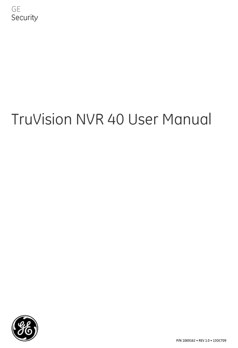
  9. GE TruVision NVR 40 User manual

GE TruVision NVR 40 User manual

© 2009 GE Security, Inc. P/N 1069163 • REV 1.0 • ISS 13OCT09
Content
Description 1
Handling safety 1
Operating safety 1
Rack system precautions 1
Package content 2
Unpacking the NVR 40 2
Before you begin 2
NVR 40 installation and rack mount 2
Front panel 2
Turning on the TruVision NVR 40 3
TruVision NVR 40 configuration 3
Front panel LEDs 4
Troubleshooting 4
Packaging and warranty conditions 4
Description
The TruVision NVR 40 is a network video recorder capable
of recording video from up to 12 or 24 IP cameras
(depending on the specific model). TruVision NVR 40 has
either two or four SATA disks (storing 1 TB each).
This quick start guide gives you step-by-step instructions on
how to install and configure the TruVision NVR 40 unit.
Important: If you are using the device within a GE-NAV 3.0
(or later) environment, go to the following site to get the
latest version of the software:
http://www.gesecurity.com/portal/site/GESecurity/menuite
m.11620ebca5cc0a06574efe10140041ca/?vgnextoid=d0b5
6e992c81e110VgnVCM100000592d7003RCRD
If you are using the VisioWave/UltraView CCS or VSC
software solution, refer to CCS or VSC user manuals.
Handling safety
A fully assembled TruVision NVR 40 unit can weigh
up to 18 kg (40 lb.). Do not try to lift this by yourself. A safe
lifting height is 20U.
Operating safety
Permanently unplug the unit if you think that it has become
damaged and before you move it.
The TruVision NVR 40 unit operates from a power supply
input voltage range of 100 to 240 VAC, 50 to 60 Hz.
A safe electrical earth connection must be provided to the
power cord.
Rack system precautions
The following safety requirements must be considered
when the unit is mounted in a rack:
• The unit must be mounted in a 19” rack.
• The rack construction must support the total weight of
the installed units and the design should incorporate
stabilizing features suitable to prevent the rack from
tipping or being pushed over during installation or in
normal use.
• When loading a rack with the units, fill the rack from
the bottom up and empty it from the top down.
• The rack design should take into consideration the
maximum operating ambient temperature for the unit,
which is 40°C (104°F).
• The rack should have a safe electrical distribution
system and it must not be overloaded by the total
number of units installed in the rack.
• The electrical distribution system must provide a
reliable earth for each unit and for the rack.
GE
Security
TruVision NVR 40 Quick Start Guide
2 TruVision NVR 40 Quick Start Guide
Package content
The package contains:
• One TruVision NVR 40 unit
• One accessories box with handles and screws
• Two power cords (one for use in EU and the other in
North America)
• One CD with TruVision NVR 40 user manuals
• One CD with GE-NAV 3.0 application software
• This quick start guide
Unpacking the NVR 40
1. Position the shipping case within 2 m (6 ft.) of the site
where you intend to use your storage unit.
2. Inspect the packaging for crushes, cuts, water damage,
or any other evidence of mishandling during transit. If
you suspect damage, photograph the packaging
before you open it.
3. Take care to open the box right side up.
4. Remove the accessories box.
5. Gently remove the TruVision NVR 40 unit from the
shipping case and put it in a safe place.
Figure 1: Unpacking the unit
Before you begin
Before you begin, make sure the site where you intend to
set up and use your storage unit has the following:
• Standard power from an independent source or a rack
power distribution unit with a UPS
• Host computer
NVR 40 installation and rack mount
A set of rack mounting handles and screws are included in
the package. To mount the unit on the rack, follow the
procedure below:
Caution: Refer to “Rack system precautions” on page 1
before you begin the assembly procedure.
1. Take out the screws and handles from the box included
in the package.
2. Using the screws, connect the handles to the NVR 40
unit. See Figure 2, item 2.
3. Lift the unit and align with rack.
4. Carefully align the unit with the rack and slide it into
position, and then fix the unit to the rack with the
screws provided. See Figure 2, item 1.
WARNING: To prevent injury, grasp the unit underneath the
lower edge, and lift with both hands. To prevent injury, keep
your back straight and lift with your legs, not your back.
Figure 2: NVR 40 handles and screw position for rack mount
Front panel
All connectors are located on the front panel of the chassis
(see Figure 3 on page 3), they include:
• One PS-2 keyboard connector (purple) and one PS-2
mouse connector (green)
• Four high-speed USB 2.0 ports
• One VGA connector
• Two Ethernet ports (10/100/1000 Mbps)
• One On/Off button
• One power socket
• One interface module
TruVision NVR 40 Quick Start Guide 3
Figure 3: Front panel connectors
1. Power socket
2. Interface module
3. Keyboard and mouse
4. Power button
5. VGA
6. LEDs
7. USB ports
8. Ethernet ports
Turning on the TruVision NVR 40
Caution: Do not operate the unit until the ambient
temperature is within the specified operating range.
To start the TruVision NVR 40 unit and connect to the
network, follow this procedure:
1. Connect the power cord to the unit. See Figure 4,
item 1.
2. Connect the Ethernet cable. See Figure 4, item 2.
3. Press the power button on the front panel, to turn on
the unit. See Figure 3.
4. The topmost LED on the front panel indicates whether
AC mains power is present; constant green indicates
when the power is on. See Figure 7 on page 4.
5. You are now ready to configure the TruVision NVR 40
unit through a Web server using a host computer. See
Figure 6 on page 4.
Figure 4: NVR 40 basic setup connections
TruVision NVR 40 configuration
The TruVision NVR 40 is designed for configuration and
installation through an Ethernet network. All configuration
and monitoring is done via a Web server.
1. Connect a host computer to the NVR 40 (this can be
done via a direct connection with a PC/notebook or
through an appropriate network.
Caution: Default IP address is 192.168.1.2. Ensure that your
computer will be able to see this device on the network.
2. Launch your favorite web-browser (for example,
Internet Explorer or Mozilla Firefox) and connect to IP
address 192.168.1.2.
3. Access the device configuration window, by selecting
Administration from the main menu. Enter the following
values in the logon and password dialog box
(see Figure 5):
User name: admin
Password: admin
Note: You can change this password later in the
“Change administrative password” window. See the
user manual for more details.
4. Select the Network Configuration icon.
5. Select the appropriate network configuration. See
Figure 6 on page 4. If in doubt, please check the
network policy with your IT department.
6. Click the Apply button at the bottom of the window, to
confirm the configuration.
7. Restart the NVR 40 unit by clicking Restart on the Web
server main menu.
8. Verify that you can connect to the Web server using the
new settings.
Your TruVision product is now ready to be used.
Figure 5: Administration logon and password dialog box
4 TruVision NVR 40 Quick Start Guide
Figure 6: Web server network configuration window
Front panel LEDs
The front panel contains three LEDs (see Figure 7).
Figure 7: Front panel LEDs
Table 1: Front panel LEDs
Icon LED Description
Power status This LED indicates when the
equipment is turned on. Constant
green indicates power on.
Storage status/activity This LED monitors the status of the
storage in the system.
VOS (video operating
system) identification LED
This LED indicates when the
embedded software (VisioWave
Security Service) has detected an
abnormal condition or a failure.*
* In case of storage failure (LED is constant red), contact technical support.
Troubleshooting
If you have a problem setting up or configuring your NVR 40
try these solutions before contacting your local supplier.
Table 2: Troubleshooting
Failure Possible reasons
Unit is overheating Fans damaged.
Cannot find storage space Hard drive failure.
Cannot connect to the Web server
of the unit
Incorrect IP configuration or
network issue.
Packaging and warranty conditions
Should there be a need for warranty repairs, return the unit
in its original packaging, otherwise warranty conditions will
be voided.

Other manuals for TruVision NVR 40

1

Other GE Network Hardware manuals

GE DEH41552 User manual

GE

GE DEH41552 User manual

GE PB3-POS-RP ProBridge User manual

GE

GE PB3-POS-RP ProBridge User manual

GE ATS1203 Assembly instructions

GE

GE ATS1203 Assembly instructions

GE NetworX NX-7002 User manual

GE

GE NetworX NX-7002 User manual

GE 0150-0241 ProBridge User manual

GE

GE 0150-0241 ProBridge User manual

GE MDS iNET Series User manual

GE

GE MDS iNET Series User manual

GE MDS TransNET User manual

GE

GE MDS TransNET User manual

GE TruVision NVR 40 User manual

GE

GE TruVision NVR 40 User manual

GE 3300 User manual

GE

GE 3300 User manual

GE MDS SD Series User manual

GE

GE MDS SD Series User manual

GE MDS 4710M User manual

GE

GE MDS 4710M User manual

GE MDS P21 Original operating instructions

GE

GE MDS P21 Original operating instructions

GE 40M06AAG User manual

GE

GE 40M06AAG User manual

Popular Network Hardware manuals by other brands

D-Link ShareCenter Pulse DNS-320 user manual

D-Link

D-Link ShareCenter Pulse DNS-320 user manual

LaCie LaCinema Classic Quick install guide

LaCie

LaCie LaCinema Classic Quick install guide

VERITAS NetBackup 5340 Appliance Product Description

VERITAS

VERITAS NetBackup 5340 Appliance Product Description

Seagate Mirra Specifications

Seagate

Seagate Mirra Specifications

ADTRAN NetVanta Series Quick configuration guide

ADTRAN

ADTRAN NetVanta Series Quick configuration guide

Fostex 8338 owner's manual

Fostex

Fostex 8338 owner's manual

Rohde & Schwarz ENV216 user manual

Rohde & Schwarz

Rohde & Schwarz ENV216 user manual

Bosslan BOSSGSM15 user manual

Bosslan

Bosslan BOSSGSM15 user manual

Intellinet 560665 user manual

Intellinet

Intellinet 560665 user manual

Iomega StorCenter ix4-200d user guide

Iomega

Iomega StorCenter ix4-200d user guide

Gigamon GigaVUE TA Series Hardware installation guide

Gigamon

Gigamon GigaVUE TA Series Hardware installation guide

WatchNet ENS-08 POE Connection guide

WatchNet

WatchNet ENS-08 POE Connection guide

Buffalo TeraStation user guide

Buffalo

Buffalo TeraStation user guide

Fike FSM-IP Installation and operation manual

Fike

Fike FSM-IP Installation and operation manual

Javad TRIUMPH-3NR user manual

Javad

Javad TRIUMPH-3NR user manual

LaCie Network Space MAX user manual

LaCie

LaCie Network Space MAX user manual

Asus AAEON FWS-8600 user manual

Asus

Asus AAEON FWS-8600 user manual

EnerSys Alpha Cordex 48-650W Technical guide

EnerSys

EnerSys Alpha Cordex 48-650W Technical guide

manuals.online logo
manuals.online logoBrands
  • About & Mission
  • Contact us
  • Privacy Policy
  • Terms and Conditions

Copyright 2025 Manuals.Online. All Rights Reserved.