manuals.online logo
Brands
  1. Home
  2. •
  3. Brands
  4. •
  5. GE
  6. •
  7. Oven
  8. •
  9. GE Monogram ZET857SYSS User manual

GE Monogram ZET857SYSS User manual

GE Monogram ®
Installation
Instructions
30" Convection
Built-In Ovens
Models
7_2T8 575YS5
7_,T857DYSB
Zk2T85713YBB
7__,7"857"WY_7
7_,T8 375YS5
7_2T837l)YSB
7_2T837BYBB
7__,7"837"WY_7
IV!'llW:lH OlIO[,1
Before you begin--Read these instructions completely and carefldly.
IMPORTANT: Save these instructions for local inspector's use,
IMPORTANT: OBSERVE ALL GOVERNING CODES AND ORDINANCES.
NOTE TO INSTALLER: Be sure to leave these instructions with the
Coilsuiner.
NOTE TO CONSUMER: Keep these instructions with your Use and Care
Book tor flttttI'e referet/ce.
This appliance must he properly grounded. See "Electrical Supply", page 9. ]
If you have questions concerning the installa-
tion of"this product, call the (;E Answer
Center #_Consumer Information Service at
800.626.2000, 24 hours a day, 7 days a week.
Proper installation is tile responsibility of the
installer. Product fi_ilut'e due to improper installation
is not covered under tile (;E Appliance V',_lrranty. See
tile [Tse K"Care Guide tor warranty intormation.
If you received a damaged oven, you should
conutct your dealer.
CAUTION:
• This oven should be installed by a qualified
installer or service technician.
• Never use the oven tor warming or heating a
room. Prolonged use of the oven without
adequate ventilation can be hazardous.
Check with local utilities for electrical codes which
apply in your area. Local codes vary. Installation,
electrical connections and grounding must comply
with applicable codes. In tile absence of local codes,
the oven should be installed in accordance with
National Electrical Code ANSI/NFPA 70-1990.
Contents Design Information
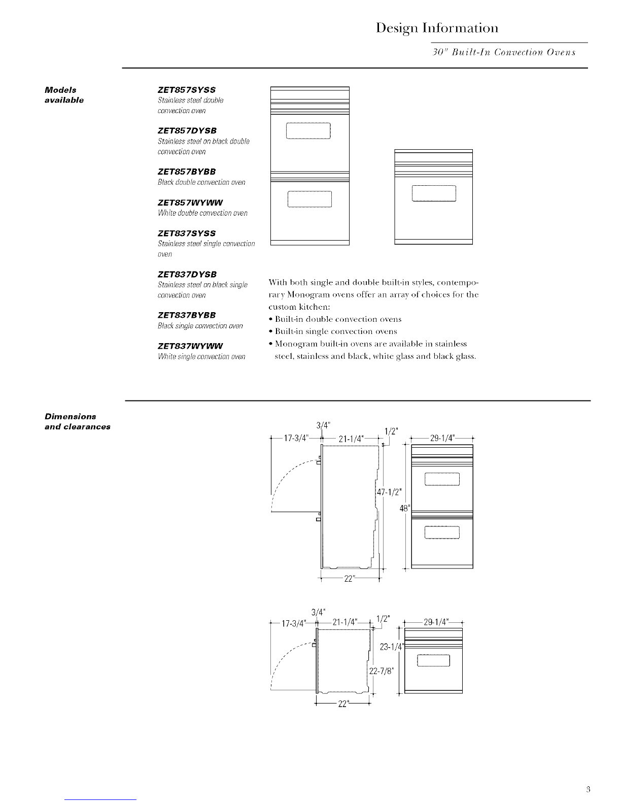
Models Available .................................................................................................................................. 3
Dimensions and Clearances ............................................................................................................... 3
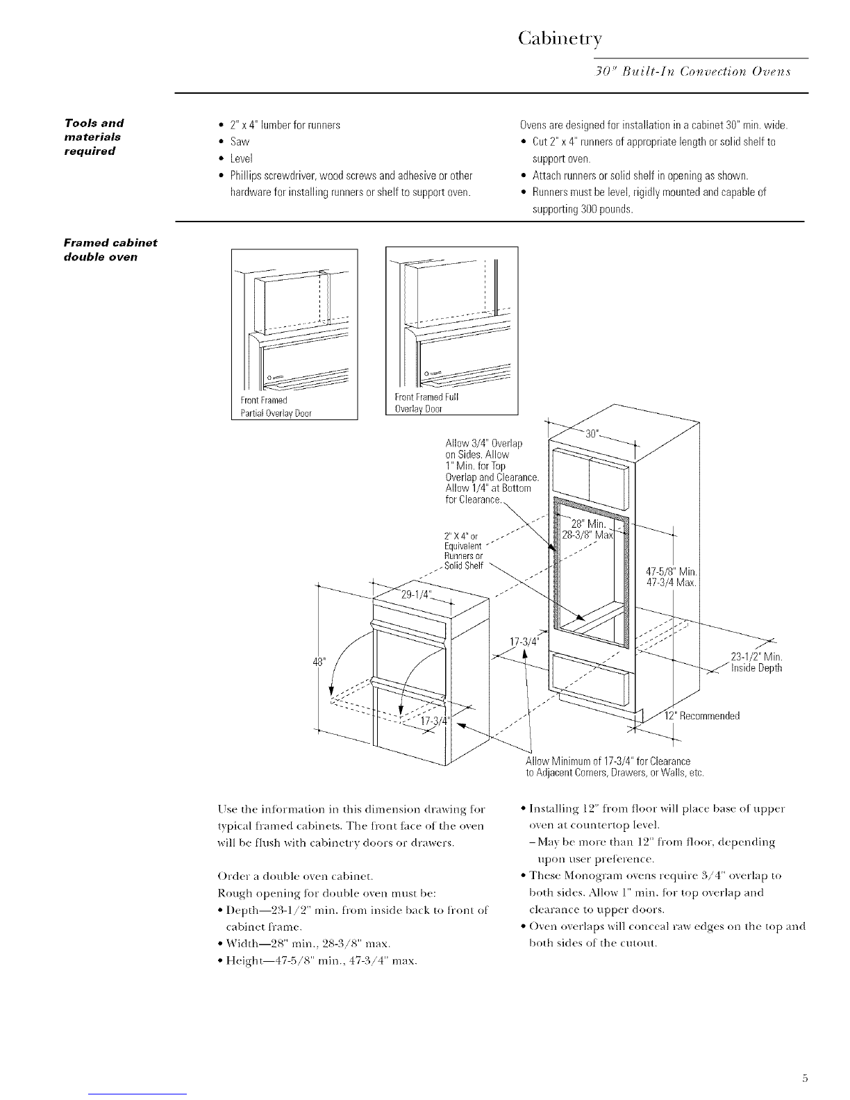
Cabinet Style Options ......................................................................................................................... 4
Cabinetry
Tools and Materials req uired ............................................................................................................. 5
Framed Cabinet, Double Oven .......................................................................................................... ,_
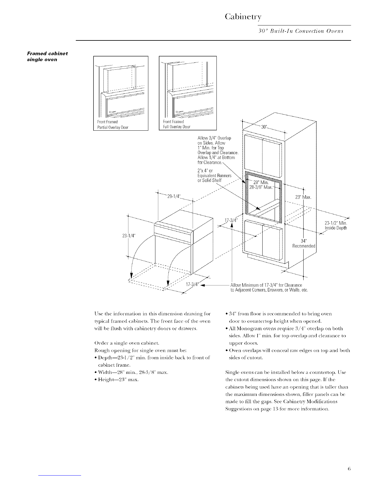
Framed Cabinet, Single Oven ............................................................................................................ 6
Fram eless Cabin ets .............................................................................................................................. 7
Installation
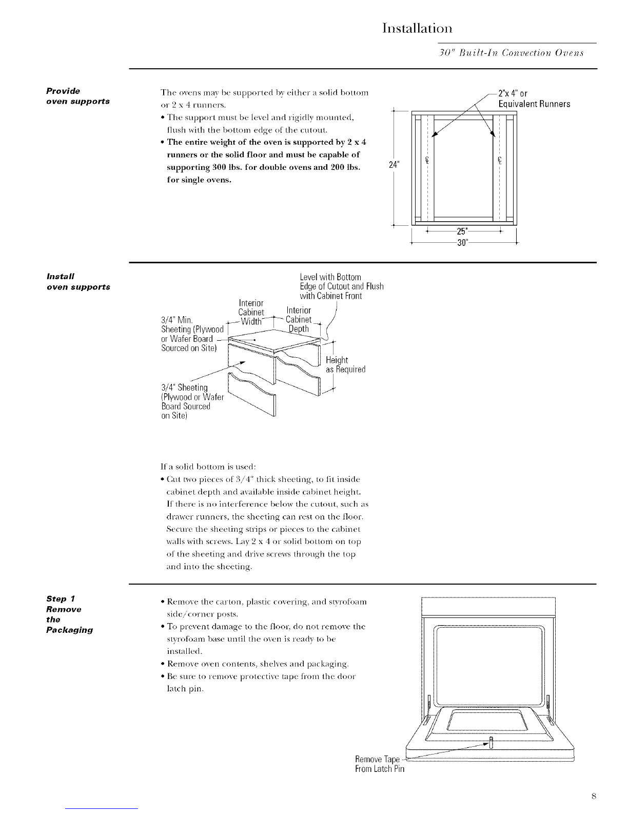
Provide Oven Supports ....................................................................................................................... 8
Install Oven Supports .......................................................................................................................... 8
Step 1: Remove the Packaging ............................................................................................................ 8
Electrical Supply .................................................................................................................................. 9
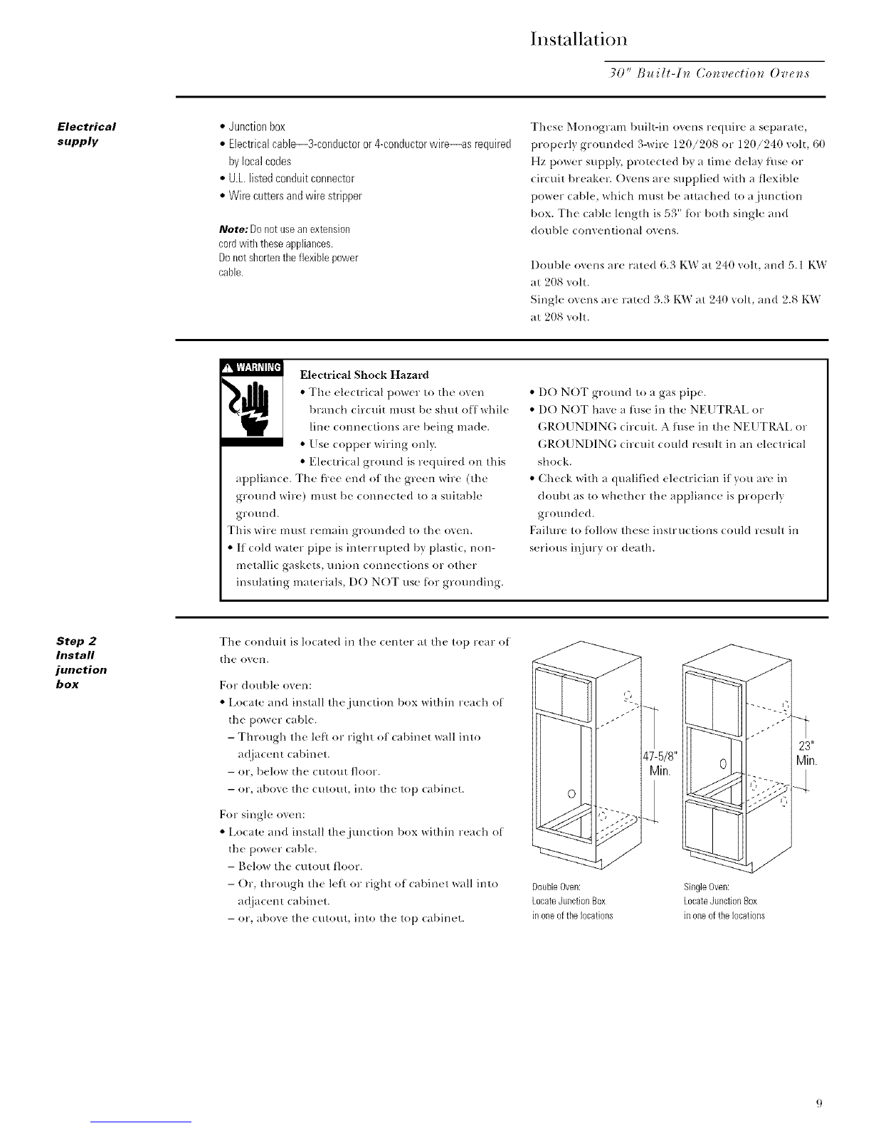
Step 2: Install.]traction Box ................................................................................................................ 9
208V Electrical Supply ....................................................................................................................... 10
Step 3: Remove Oven Doors ............................................................................................................. 11
Step 4: Rotate Cable through Ctttt)ttt ............................................................................................... l l
Step 5: Secm'e Oven to Cabinet ........................................................................................................ l 1
Step 6: Replace the Oven Door ........................................................................................................ 12
Step 7: Cmmect Electrical ................................................................................................................. 19
Cabinetry Modification Suggestions
Determine Need for Fillet" Panels ..................................................................................................... 13
Fillet" Panel Construction .................................................................................................................. 13
(',tit Rail for Fillet" Panel .................................................................................................................... 14
(:tit Appearance Panel ...................................................................................................................... 14
Determine Location of Cleats ........................................................................................................... 14
Cut and Secm'e Cleats tit Fillet" Panel ............................................................................................... 15
Secm'e Rail to Appearance Panel ..................................................................................................... 15
Secure Assembled Fillet" Panel to Cabinet ....................................................................................... 15
Design hdbrmation
30" Built-I_ Co_vectio_ Ove_s
Models
available ZET857S YSS
Stainlesssteeldouble
convection oven
ZETa57D YSB
Stainlesssteelonblackdouble
convection oven
ZET857BYBB
Blackdoubleconvectionoven
ZET85 7WYWW
Whitedoubleconvectionoven
ZETa37S YSS
Steinlesssteelsingleconvection
even
ZET837D YSB
Stainlesssteelonblacksingle
convection oven
ZET837BYBB
B/a_ singleconvectionoven
ZET837WYWW
Whitesingleconvectionoven
I }
With both single and double built-in styles, contempo-
rary Monogram ovens ottbr an array of choices for the
custom kitchen:
• Built-in double convection ovens
• Built-in single convection ovens
• Monogram built-in ovens are available in stainless
steel, stainless and black, white glass and black glass.
Dimensions
and clearances
7-3/4"
3/4"
_ 17-3/4"_L 21-1/4"--
i
L
22'_
/2" --29-1/4"--
23-
:-7/8
Design hdbrmation
30" Built-I_ (o_vectio_ Ove_,_
Cabinet style
options
FrontFramedPartialOverlayDoor Front FramedFuji Overlay Door
Monogram ovens are installed directly into a wall 01-
wall oven cabinetry, 30" minimum width. The fl-ont
sm-tilce of the ovens will be nearly tlush with sur-
rounding cabinetry. To obtain optimal appearance,
cabinet cutouts must be exact. The examples shown
here illustrate typical styles of 30" cabinets and oven
fit. Installation instructions tot each of these basic
cabinetry styles are provided in this section.
Designer Note: Whenever
possible,alignthe ovenwith
cabinetry detailssuch as
drawers,doorsandreveals.
f_ Framebss
Cabinetry
30" t_uill-I_ (o_veclio_ Ove_s
Tools and
materials
required
Framed cabinet
double oven
•2"x 4" lumberfor runners
• Saw
• Level
• Phillips screwdriver,wood screws andadhesiveor other
hardware for installing runnersor shelfto support oven.
Ovensare designedfor installation in a cabinet 30" rain. wide.
• Out2" x4" runners ofappropriate length or solid shelfto
support oven.
• Attach runnersor solid shelf in openingas shown.
• Runnersmust be level, rigidly mounted and capable of
supporting 3(}0pounds.
FrontFramed
PartialOverlayDoor
FrontFramedFull
Overlay Door
Allow 3/4" Overlap
onSides.Allow
1"Min. for Top
OverlapandClearance.
Allow 1/4" at Bottom
for Clearance.
23-1/2"Min.
_"Recommended
Use the inlormation in this dimension drawing tor
typical trained cabinets. The tvont titce of"the oven
will be f]ush with cabinetry doors or drawers.
Order a double oven cabinet.
Rough opening for double oven must be:
• I)epth--23-1i2" min. fiom inside back to tront of
cabinet fl-ame.
• Width--28" rain., 28-3/8" max.
• Height--47-5/8" rain., 47-3/4" max.
Allow Minimumof 17-3/4"for Clearance
to AdjacentCorners,Drawers,or Walls,etc.
• Installing 12" from floor will place base of upper
i)verl at cotnlteltop level.
-May be more than 12" from floor, depending
upon user preference.
• These Monogram ovens require 3/4" overlap to
both sides. Allow 1" rain. fbr top overlap and
clearance to upper doors.
• t)ven overlaps will conceal raw edges on the top and
both sides of the cutout.
Cabinetry
30" Buill-I_ (o_vr'clio_ Ovr'_s
Framed cabinet
single oven
FrontFramed
PartialOvedayDoor
FrontFramed
Full Overlay Door
Allow 3/4" Overlap
onSides.Allow
1"Min. forTop
OverlapandClearance.
Allow 1/4" at Bottom
2"x4" or
Eq_
or SolidShelf
23-1/4"
23-I/2" Min.
InsideDepth
Allow Minimumof 17-3/4"for Clearance
to AdjacentCorners,Drawers,or Wails,etc.
Use the inlormation in this dimension drawing tor
typical h-amed cabinets. The h-ont li_ce of the oven
will be flush with cabinetry doors or drawers.
Order a single oven cabinet.
Rough opening tot single oven must be:
• I)epth--23-1/2" rain. fl-om inside back to fi-ont of
cabinet hame.
• Width--28" rain., 28-3/8" max.
• Height--23" max.
• 34" h'om floor is recommended to bring oven
door to countertop height when opened.
• All Monogram ovens require 3/4" overlap on both
sides. Allow 1" rain. tot top overlap and clearance to
upper doors.
• Oven overlaps will conceal rmv edges on top and both
sides of cutout.
Single ovens can be installed below a countertop. Use
the cutout dimensions shown on this page. If the
cabinets being used have an opening that is tuller than
the maximum dim_ nsions shown, filler panels can be
made to fill the gaps. See Cabinet1T Modifications
Suggestions on page 13 tot more infbrmation.
Cabinetry
30" Buill-I_ (o_veclio_ Ove_s
Frameless
cabinets
Frameless
Trim Strip or UpperCabinet Shelf
With Finished Endslike Cabinet
Sides. 1" Min. Deepfor Oven
Flange Overlap and
Cabinet Depth 23-1/2" Min.
FromInside Back to
of Cabinet Frame or Side
Panel,Excluding Doors
or Drawer Fronts.
_3O"f
J
O0
3/4" 0
Shelf Cut Back Flushwith 0
Front of Side Panel
See page 9.
Double Ovens
47-5/8" Min.
Single Ovens
23" Min.
FabricateFiller
Panelif Necessary,Similar
to DrawerFrontor
UpperCabinetDoors
or OrderAdditional
DrawerFront
1/2" Cleatsto
HoldOvenMounting
Screws,MeasureOven
to FindExactLocations.
FinishTrimStrip1/4"Min.
DeepforClearance.
ToObtainInstallationHeight
fromFloorit maybeNecessary
to InstallaLowerFillerPanel.
Use the inlormation in this dimension drawing %r
typical h-ameless cabinets. The h-ont t_me of the oven
will be f]ush with cabinetry doors or drawers.
Whenever possible, order 30" h-am_less cabinet with
the cutout sized to fit the oven. If yon are using stock
cabinets, additional finished fillet- pieces may be
required to covet openings.
Rough opening tot single and double ovens:
• I)epth--23-1/2" rain. liom inside back to flont of
cabinet or side panel, excluding doors or drawer
tionts.
• Width--28" rain.
- Frameless cabinet cutout width may be up to
28-3/4". Add 1/2" cleats to the sides, flush with
the tiont edge of the side panels to accept
mounting screws.
• Height--tot double oven 47-5/8" rain.
• Height--tor single oven 23" min.
Both single and double ovens require 3/4" overlap
around edges of opening on both sides. Allow 1/2"
tor top overlap.
• Allow 1/8" clearance between top of oven and
cabinet door ol- panel and 1/8" between bottom of
oven and cabinet drawer.
• Installation of double oven requires a total height ot"
48-1/4" including clearances at top and bottom.
• Installation of single oven requires a total height
of 23-1/2" including clearances.
Installation
30" Built-I_ ( o_vectio_ Ove_L_
Provide
oven supports The ovens may be supported by either a solid bottom
OY 2 X 4 YunneFs,
• The support must be level and rigidly monnted,
flush with the bottom edge of the cutout.
• The entire weight of the oven is supported by 2 x 4
runners or the solid floor and must be capable of
supporting 300 lbs. for double ovens and 200 lbs. 24"
for single ovens.
/_ 2"x4"or
EquivalentRunners
;/x \\
'_ 'i
i
i
i
ti
i
i
i
i
i
i
i
i
i
i
i
i
i
i
i
i
i
i
i
i
i
i
i
i
i
i
i
i
i
i
_25"_ 30"
Install
oven supports
Levelwith Bottom
Edgeof CutoutandFlush
with CabinetFront
Interior !
Cabinet Interior J
3/4" Min. 4,_-Width_l_- Cabinet /
Sheeting(Plywood Depth ](
or WaferBoard _ _._
SourcedonSite) __- --Tp__..------._ He_ht ,
__ _ II % asrlequlrea
3/4" She_ [__"_ _
(PlywoodorWafer _ '_ '"_--
BoardSourced _ I[
on Site)
Ifa solid bottom is used:
• Cut two pieces of 3/4" thick sheeting, to tit inside
cabinet depth and awfilable inside cabinet height.
If there is no interfbrence below the cutout, such as
drawer r-nnners, the sheeting can rest on the floor.
Secure the sheeting strips or pieces to the cabinet
walls with screws. Lay 2 x 4 or solid bottom on top
of the sheeting and drive screws through the top
and into the sheeting.
Step 1
Remove
the
Packaging
• Remove the carton, plastic covering, and styrofbam
side/corner posts.
• To prevent damage to the floor, do not renlove the
sl}rofl)an_ base until the oven is ready to be
installed.
•Remove oven contents, shelves and packaging.
• Be sure to remove protective tape ti'om the door
latch pin.
RemoveTape/_
FromLatchPin
Installation
30" Built-I_ ( o_vedion Ovens
Electrical
supply
•Junction box
•Electrical cable--3-conductor or 4-conductorwire--as required
by local codes
• U.L.listed conduit connector
• Wire cutters and wire stripper
Note: Donotuseanextension
cordwith theseappliances.
Donotshortentheflexible power
cable.
These Monogram built-in ovens require a separate,
properly grounded 3-wire 120/208 or 120/240 volt, 60
Hz power supply, protected by a time delay ltrse or
circuit breaker. Ovens are supplied with a flexible
power cahle, which must be attached to a junction
box. The cable length is 53" tor both single and
double conventional ovens.
I)ouble ovens are rated 6.3 KW at 240 volt, and 5.1 KW
at 208 w)lt.
Single ovens are rated 3.3 KW at 240 volt, and 2.8 KW
at 208 volt.
Electrical Shock Hazard
• The electrical power to the oven
branch circuit must be shut off while
line connections are being made.
• Use copper wiring only.
• Electrical ground is required on this
appliance. The fl-ee end of the green wire (the
ground wire) must be connected to a suitable
ground.
This wire must remain grounded to the oven.
• If cold water pipe is interrupted by plastic, non-
metallic gaskets, union connections or other
insulating materials, I)O NOT use tbr grounding.
• DO NOT grotmd to a gas pipe.
• DO NOT have a fuse in the NEUTI_M+ oi"
GROUNI)ING circuit. A fl:se in the NEI ?Tl0LkI+or
GROUNI)ING circuit could result in an electrical
shock.
• Check with a qualified electrician if you are in
doubt as to whether the appliance is properly
grounded.
Failure to tbllow these instructions could result in
serious i:_iury ol- death.
Step 2
Install
junction
box
The conduit is located in the center at the top rear of
the oven.
FoI" dotlble oven:
• Locate and install the junction box within reach of
the power cable.
- Through the leli or right of cabinet wall into
a(!iacent cabinet.
- or, below the cutout tloor.
- or, above the cutout, into the top cabinet.
For single oven:
• Locate and install the junction box within reach of
the power cable.
- Below the cutout [loot.
- Or, through the left or right of cabinet wall into
a(!iacent cabinet.
- or, above the cutout, into the top cabinet.
DoubleOven:
LocateJunctionBox
in oneofthe locations
23"
¢7-5/8" "n
Min.
Single Oven:
LocateJunction Box
in oneof the locations
Installation
30" Built-I_ (o_vection Ove_s
208V
Electrical
supply
_ Th_se OX_ llS aye pF_-wh-_ d _)t- connec-
]tion lo 24¢) volt, 60 Hz., suppl). If connecting
to a 208 _olt supply modifications must be made.
to _l 2'08 vol
If connecting to a 208 volt, 60 Hz., supply, a jumper
mtlst be tlsed across two tetmitlals.
•For double ovens, there are lwojumpers, one fin- the
upper oven, one for the lower oven.
• For single ovens there is one jumper.
Single ovens,
double ovens-
(upper oven)
Jumper LoosenScrews
Jumper Tighten Screws
To connect to 208 volt circuit:
•Remove the access panel(s) located on the back of
the ovens.
• Loosen the first and second screws ill the terminal
block as shown.
• Remove the jumper and place between the fh-st and
second screws, tighten the screws to hold the
jumper in place.
• Replace the access panel(s).
Double ovens-
(lower oven) I)ouble ovens-Lower
JumperL00 n
o
Jumper Loosen Screws
Jumper Tighten Screws
10
Installation
30" Built-b_ ( o_vectio_ Ove_,_
Step 3
Remove
Oven
Door(s)
Caution: Donotlift theovenorovendoorwitb handle.
Locked
Ne Latch
•()pen the door lttlly.
• Push hinge latches up to lock hinges in open
position.
• (;rasp each side of door and pull the door straight
out and away fi-om tlle oven.
• I.ay the oven door on packaging to prevent
scratching.
Step 4
Route
cable
through
cutout
Step 5
Secure
oven
to cabinet
Caution: Oven{s)areveryheavy.2peopleare requiredto lift oven(s)
into theopening.Ovenshavesidebandies.Graspsidehandlewith one
handand intoovenopeningwith otberband.Lift theovento the
cabinetopening,verycarefully.
With oven in front of cabinet opening:
• Insert power cable into cabinet opening.
• Lift the oven into opening while continuing to rived
the cable in the direction of" the installed junction
box. Be sure the cable does not get pinched between
the back of the oven and cabinet wall.
ShippingBase
• Slide oven into cabinet opening.
• I)rill 3/32" pilot holes into cabinet flame through
mounting holes in oven fl'ont li-ame.
• Secure oven to cabinet with screws fllrnished.
-Single ovens, use 2 screws, one on each side.
-I)ouhle ovens, use 4 screws, 2 on each side.
crews provided. Failur_ to do so could
ause the oven to mo_ or tip dtlFing tlse
tnd result ill p_rsonal il_iur }.
(DO ©
/
] 1
Installation
30" Built-I. (o_vectio. Ove.s
Step 6
Replace the
oven door
• Grasp door th-n:ly on both sides,
• Slide the hinge slots ill the bottom of the cloor over
the hinges.
• Push tile cloor all the way in against oven.
• ()pen the door thlly and push hinge latches down,
as illustrated, on both sides to secure.
• (;lose the door and open slowly to be sure it moves
smoothl>
Step 7
Connect
electrical
Electrical Shock Hazard
• Electrical ground is required on this
appliance.
• I)o Not connect to the electrical
supply until appliance is
permanently grounclecl.
• Disconnect power to the junction box beli>re
making the electrical connection.
• This appliance must be connected to a grounded,
metallic, permanent wiring system, or a grounding
connector shoulcl be connected to tile grounding
terminal or wire lead on the appliance.
Failure to do so could result in a fire, personal
mjnry or electrical shock.
• When connecting to a 3-conductor branch circuit:
-Connect oven recl lead to branch circuit recl leacl.
-Connect oven |alack lead to branch circuit black
lead.
-Connect oven bare copper conductor and white
lead to branch circuit neutral lead (white or gray).
Junct:on Branch Circuit
Red Black
White.
Bareo
Green
Wires CaNe UL-Listed
FromOven ConduitConnector
• When connecting to a 4-conductor branch circuit:
-Connect oven recl lead to branch circuit recl leacl.
-Connect oven |alack lead to branch circuit black
lead.
-Break connection between oven white lead and
oven bare copper cl)t)dtlctor.
-Connect oven white lead to branch circuit neutral
lead (white or gray).
-Connect oven bare copper conductor to branch
circuit grouncl lead (green or bm-e copper).
Note: Usecopperwire only.
Junction Branch Circuit
Red White
Wires
Barn or
Green CaNe UL Listed
Wires From Oven Conduit Connector
12
Installation
30" Built-I_ (o_vectio_ Ove_s
Determine
need for
rifler panels
If dae cabinets being used have an opening that is
taller than the maximmn dimensions indicated tbr
the ovens, filler panels can be made to till the gaps.
Stock filler strips are usually awdlable or fbr larger
gaps order an extra drawer fl-ont. I)rawer honts are
recommended because they will match tl_e cabinetry
and have finished edges. Any cut edges will be seen
and should be finished.
Frameless cabinets usually come with a fl-ont panel
covering the opening. Fox-the optimum finished look,
this panel can be removed and used to construct filler
panels.
The oven support floor and supports should be
installed at the required locations.
If there is a gap belween the oven support floor and
the bottom of the opening, a bottom filler panel
should be constructed to fill the gap.
Measure from the oven support floor to the top of"the
opening. If the opening height is larger than the
maximmn cutout height, a filler panel should be
constructed to fill the gap.
FillerPanel
Overlaps
Slightly like
DoorsAbove
FillerPanel
Overlaps
[awer Shelf
Slightly
Filler panel
construction We suggest that the filler" panel be constructed using
4 pieces:
• Appearance panel to match doors and drawers.
• A fail which will be covered by the oven overlaps
and conceal any slight gap between the top or
bottom of the oven and the start of the filler- panel.
The fhce of the rail should be made of finished
matching material; the cut edges and ends do not
need to be finished.
• Cleats which will be used to secure the filler panel
and rail to the cabinet. One for each side.
Cleals
/
_Screws
Top FillerPanel
Appearance Panel
_J
Rail
BottomFillerPanel
Cleats
Scraws_
'_ Screws
\
Cleats
Rail
\\
AppearancePanel
Screws_]_:_
/
Cleats
13
Cabinetry Modification Suggestions
30" Buill-I_ (o_vedio_ Ovens
Cut rail
for filler
panel
Cut the rail out of linished material:
• Tile width should match cabinet opening width.
• Tile height of tile top rail should be enough to
securely attach the rail to dae appearance panel,
plus 1/4" oven trim overlap.
• Tile height of tile bottom rail should be enough to
securely attach the rail to tile appearance panel,
plus 7/8" oven trim overlap.
• Tile height of both the top and bottom rails should
be a_!justed depending upon the height of the gap
to be filled or to enhance appearance.
TopRail
Lengthto Match
CabinetCutoutOpening
BottomRail
Lengthto Match
Cabinet Cutout Opening
Cut appearance
panel Else drawer fl-onts for appearance panels or cut
finished material and finish raw edges.
• The appearance panel width should match drawer
fronts or doors.
• Make the appearance panel appropriate height to
fill the gap above or below the oven, allowing for
reveals and overlaps to match existing drawers or
dooYs,
Width toMatch
drawers ordoors
Determine
location
of cleats _ FramedCabinet _'
Appearance Panel
MarkCorners
with Pencil
InsideFront
of Cabinet
Frameless Cabinet
with Pencil
InsideFront
of Cabinet
• To find the exact position of the cleats, place the
appearance panel onto tile cabinet in desired
position and align to match tile other drawers and
dooI's.
• Use a pencil to mark tile back side of tile panel
where it meets the cabinet corners.
f 4
Cabinetry Modification Suggestions
30" Buill-I_ (o_vedio_ Ove_L_
Cut and
secure cleats
to filler panel
Appearance
Panel
TopFillerPanel
Cle{
Appearance
Panel
BottomFillerPanel
Cleat
Secure rail
to appearance
panel
For the top filler panel:
• Cut 2 cleats octt of 3/4" thick material, approxi-
mately 1-1/4" wide.
• Cut tile cleats to a length leaving apwoximately
1/2" at tile bottom of the appearance panel to
attach tile rail.
• l'osition the outside edge and top of" the cleat
against tile corner pencil marks.
• Secure the cleat to tile appearance panel with
SC f'ews.
Note: Tl_escrewssl_ouidhe longenoughto securethecleats to tl_e
filler panelwitl_outpenetratingtile appearanceside.
For the bottom filler panel:
• (;tat 2 cleats out of" 3/4" thick material, approxi-
mately 1-1/4" wide.
• (;tit the cleats to a length leaving approximately
1/2" at tile top of the filler panel to attach the rail.
• Position the outside edge ancl bottom of" the cleat
against the corner pencil marks.
• Secure the cleat to tile appearance panel with
sciews.
Note: if appearancepanelis verynarrow,cleats can beattachedto
tile rail.
TopFillerPanel
Cleats Cleats
Appearances/Panel
Screws _ ScrewsRail
%ttom FillerPanel
Rail _::_
Screws \\ Screws
Cleats AppearancePanel Cleats
• l'lace rail against cleats ancl flush with the outsicle
edges of the cleats. Secure with wood screws. If the
appearance panel is very narro_: cleats can be
attached to the rail.
Note: Thescrewsshould beions enoughto securerail to tl_efiller
panelwitllout penetratingtl_efinished face of tile filler panel.
Secure
assembled
filler panel
to cabinet
Cleats\
Framed Cabinet
FillerPanel
Attach
WithScrews
InsideFrontofCabinet
/
/Cleats
/
Cleats
Frameless Cabinet
Attach
With Screws
InsideFrontofCabinet
Cleats
)
•Ilace filler panel in proper position. To attain
proper relationship to ac[jacc nt ch-awers ancl doors
you may need to space tile filler panel ottt fiom the
cabinet face!edges clsing ch-awer bumpers or other
spacers.
15
Monogram:
General Electric Company
Louisville, KY 40225
NOTI_]: While performing installationsdescribedinthis book,
safetyglassesor gogglesshouldbe worn.
Monog'*zzm product or s_n,ice, call (;l" Answer Ck_zl_r_"_
.nzsumer i_/b_w_alio_z _i_ _.al _f)f). 626.2000 a_O'
lim_< da3 oz _ligfiL
For Mo_uNram local s_.rvice i_z youz a_va, _all
l 800444 1845.
N()TE: P) oduct imp]ovemenl is a conlimfing ende tvol at (;ene]al
Elecl_ic Therefore, materials, appearance and specificalioiJs are
sul!lect to cl_J_ge witho_l J_<_ice
Pub No 49-8791
Dwg No 164DS333P046
© 1997 (;E Appliances
(ND 521) 3/97

This manual suits for next models

7

Other GE Oven manuals

GE JKP86 User manual

GE

GE JKP86 User manual

GE JKC06GJ Specification sheet

GE

GE JKC06GJ Specification sheet

GE Oven User manual

GE

GE Oven User manual

GE JKP35 User manual

GE

GE JKP35 User manual

GE SCB1001MSS User instructions

GE

GE SCB1001MSS User instructions

GE JKP37G User manual

GE

GE JKP37G User manual

GE JKP30 User manual

GE

GE JKP30 User manual

GE JGRC14 User manual

GE

GE JGRC14 User manual

GE 164D2966P122 User manual

GE

GE 164D2966P122 User manual

GE CT9070 User manual

GE

GE CT9070 User manual

GE Profile PVM1790 User manual

GE

GE Profile PVM1790 User manual

GE JVM1600 Series User manual

GE

GE JVM1600 Series User manual

GE JTP10GS User manual

GE

GE JTP10GS User manual

GE Profile advantium SCB1000 User manual

GE

GE Profile advantium SCB1000 User manual

GE JKP20 User manual

GE

GE JKP20 User manual

GE Advantium ZSA1201 User manual

GE

GE Advantium ZSA1201 User manual

GE Monogram ZET1SMSS User manual

GE

GE Monogram ZET1SMSS User manual

GE JKS06 User manual

GE

GE JKS06 User manual

GE JRP20 User manual

GE

GE JRP20 User manual

GE JGRP18GEL User manual

GE

GE JGRP18GEL User manual

GE CT918STSS User manual

GE

GE CT918STSS User manual

GE Monogram ZET1SMSS User instructions

GE

GE Monogram ZET1SMSS User instructions

GE CT9070SHSS User manual

GE

GE CT9070SHSS User manual

GE JKP15 Series User manual

GE

GE JKP15 Series User manual

Popular Oven manuals by other brands

Impecca Courant TO9M1 user manual

Impecca

Impecca Courant TO9M1 user manual

NEFF B64VS71 0B Series User manual and installation instructions

NEFF

NEFF B64VS71 0B Series User manual and installation instructions

Siemens HM633GB.1 User manual and installation instructions

Siemens

Siemens HM633GB.1 User manual and installation instructions

Guspro BB-8416884 Operation & maintenance manual

Guspro

Guspro BB-8416884 Operation & maintenance manual

Bosch HBA 23B1.0 S Instructions for use

Bosch

Bosch HBA 23B1.0 S Instructions for use

Bosch HBS573B.0B User manual and installation instructions

Bosch

Bosch HBS573B.0B User manual and installation instructions

Bosch HBF534E 0Q Series User manual and installation instructions

Bosch

Bosch HBF534E 0Q Series User manual and installation instructions

AEG KSK788280M user manual

AEG

AEG KSK788280M user manual

Comfee CTO-E101A(BK) instruction manual

Comfee

Comfee CTO-E101A(BK) instruction manual

TREVIDEA Girmi FE60 user manual

TREVIDEA

TREVIDEA Girmi FE60 user manual

Piper Products CHEF SYSTEM CS2-10 Specifications

Piper Products

Piper Products CHEF SYSTEM CS2-10 Specifications

APW Wyott X*WAV 1417 Installation and operating instructions

APW Wyott

APW Wyott X*WAV 1417 Installation and operating instructions

Fagor MIDI45 Installation, use and maintenance

Fagor

Fagor MIDI45 Installation, use and maintenance

Progress PBN12001X user manual

Progress

Progress PBN12001X user manual

Whirlpool AKZM 750 User and maintenance manual

Whirlpool

Whirlpool AKZM 750 User and maintenance manual

Electrolux OKC8P31X user manual

Electrolux

Electrolux OKC8P31X user manual

Monogram ZTSX1DP owner's manual

Monogram

Monogram ZTSX1DP owner's manual

Hix SubliPro-Ct owner's manual

Hix

Hix SubliPro-Ct owner's manual

manuals.online logo
manuals.online logoBrands
  • About & Mission
  • Contact us
  • Privacy Policy
  • Terms and Conditions

Copyright 2025 Manuals.Online. All Rights Reserved.