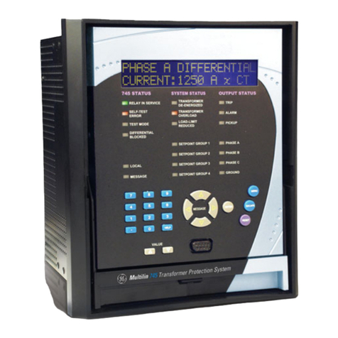
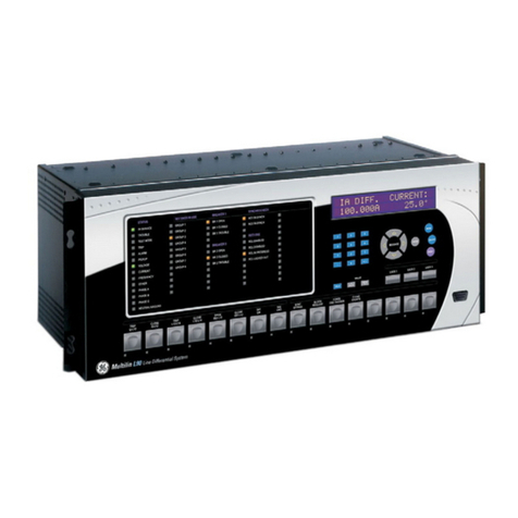
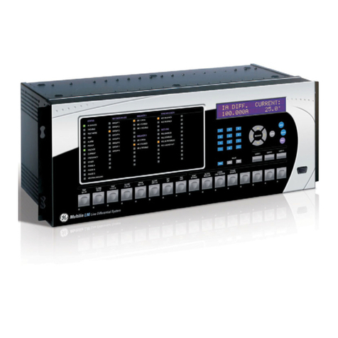
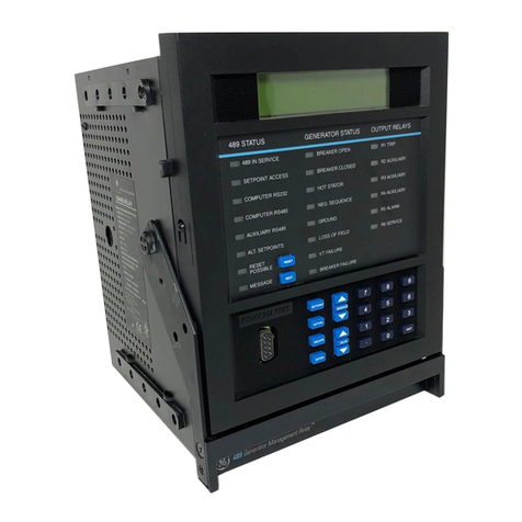
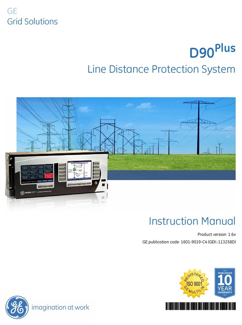
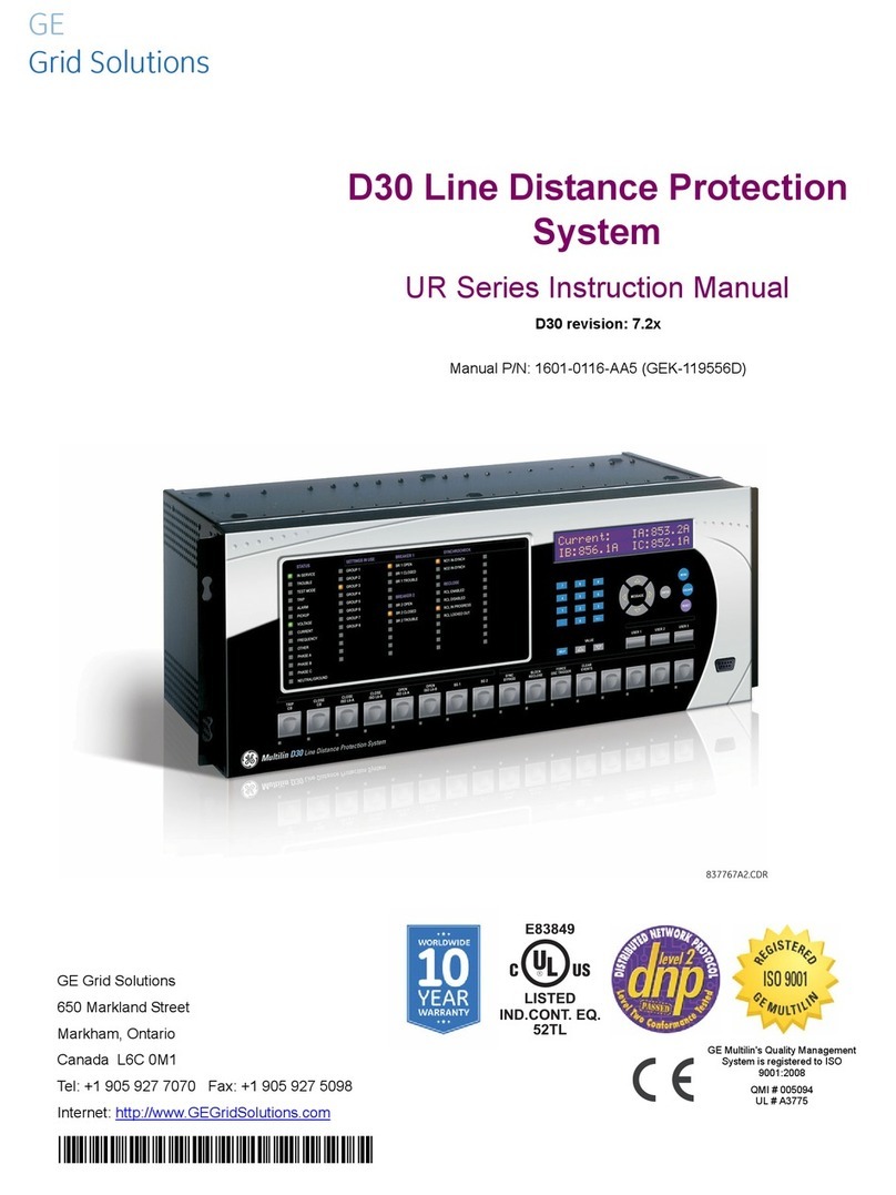
GE D90 Plus User manual

GE
Digital Energy
Instruction Manual
Product version: 1.9x
GE publication code: 1601-9019-F3 (GEK-113468C)
D90Plus
Line Distance Protection System
1601-9019-F3
IISO 9001
G
N
E
I
L
M
I
U
T
L
T
E
S
I
R
G
E
E
D
R

Copyright © 2015 GE Multilin Inc. All rights reserved.
D90Plus Line Distance Protection System Instruction Manual for version 1.9x.
D90Plus, EnerVista, EnerVista Launchpad, EnerVista URPlus Setup, FlexLogic, FlexCurves,
FlexAnalog, FlexMatrix, Digital Energy, Multilin, and GE Multilin are trademarks or registered
trademarks of GE Multilin Inc.
The contents of this manual are the property of GE Multilin Inc. This documentation is
furnished on license and may not be reproduced in whole or in part without the permission
of GE Multilin. The content of this manual is for informational use only and is subject to
change without notice.
Part number: 1601-9019-F3 (July 2015)

D90PLUS LINE DISTANCE PROTECTION SYSTEM – INSTRUCTION MANUAL iii
D90Plus Line Distance Protection System
Table of contents
1 INTRODUCTION Safety symbols and definitions....................................................................................1
For further assistance ...................................................................................................1
2PRODUCT
DESCRIPTION
Product description........................................................................................................3
Firmware architecture .................................................................................................................................4
Hardware architecture ................................................................................................................................5
Communications overview ........................................................................................................................8
Front panel interface ....................................................................................................................................8
Protection features.....................................................................................................................................10
Automation features..................................................................................................................................14
Equipment manager features ............................................................................................................... 15
Metering and monitoring features......................................................................................................15
Digital fault recorder features............................................................................................................... 16
Communications features....................................................................................................................... 17
Order codes ...................................................................................................................18
Specifications................................................................................................................18
Protection specifications..........................................................................................................................18
Automation specifications ......................................................................................................................29
Equipment manager.................................................................................................................................. 30
Metering specifications ............................................................................................................................ 31
Digital fault recorder specifications....................................................................................................32
Front panel interface ................................................................................................................................. 33
Hardware specifications..........................................................................................................................34
Communications specifications ...........................................................................................................36
Inter-relay communications specifications ....................................................................................37
Test specifications.......................................................................................................................................37
Environmental specifications ................................................................................................................38
Approvals and certification.....................................................................................................................38
3 INSTALLATION Unpack and inspect .....................................................................................................39
Panel cutouts ................................................................................................................40
Dimensions.....................................................................................................................................................40
Rear terminal layout .................................................................................................................................. 41
Wiring .............................................................................................................................42
Typical wiring.................................................................................................................................................42

iv D90PLUS LINE DISTANCE PROTECTION SYSTEM – INSTRUCTION MANUAL
TABLE OF CONTENTS
Dielectric strength .......................................................................................................................................43
Main processor module ............................................................................................................................44
Communications module.........................................................................................................................46
Power supply module.................................................................................................................................46
AC modules.....................................................................................................................................................47
Contact input and output modules .....................................................................................................49
Inter-relay communication modules..................................................................................................53
Install software .............................................................................................................59
System requirements.................................................................................................................................59
Install software..............................................................................................................................................60
Connect for first time with Quick Connect.......................................................................................62
Configure the D90Plus for software access ......................................................................................63
Activate the D90Plus ....................................................................................................................................66
Connect to the D90Plus ..............................................................................................................................66
4 FRONT PANEL
INTERFACE
Front panel ....................................................................................................................69
Front panel operation..................................................................................................70
Metering menu..............................................................................................................71
Control menu.................................................................................................................72
Digital fault recorder menu........................................................................................73
Equipment manager menu.........................................................................................75
Annunciator...................................................................................................................76
Annunciator operation ..............................................................................................................................76
Self-test page.................................................................................................................................................78
Product information page........................................................................................................................78
Communication status page..................................................................................................................78
5 ENERVISTA
SOFTWARE
Introduction...................................................................................................................81
Settings templates .......................................................................................................81
Enable the settings template in offline mode.................................................................................82
Enable the settings template in online mode.................................................................................82
Edit the settings template........................................................................................................................82
Add password protection to a template...........................................................................................83
View the settings template......................................................................................................................84
Remove the settings template...............................................................................................................85
Secure and lock FlexLogic equations........................................................................85
Lock FlexLogic equations.........................................................................................................................86
Lock FlexLogic equations to a serial number .................................................................................86
Settings file traceability ..............................................................................................87
Settings file traceability information...................................................................................................88
Online device traceability information...............................................................................................89
Additional traceability rules ....................................................................................................................89
6 COMMUNICATIONS Communications overview .........................................................................................91
Ethernet network topology......................................................................................................................91
Network settings ..........................................................................................................94
Ethernet ports................................................................................................................................................95
TFTP protocol .................................................................................................................................................98
SNTP protocol ................................................................................................................................................99
HTTP protocol..............................................................................................................................................100
Network filtering........................................................................................................................................101
Ethernet actual values............................................................................................................................102
Remaining TCP/IP connections ..........................................................................................................103

TABLE OF CONTENTS
D90PLUS LINE DISTANCE PROTECTION SYSTEM – INSTRUCTION MANUAL v
PRP actual values ..................................................................................................................................... 104
Date and time actual values and commands ............................................................................ 104
Modbus communications......................................................................................... 105
Modbus protocol....................................................................................................................................... 106
Modbus user map .................................................................................................................................... 106
DNP communications ............................................................................................... 107
DNP protocol............................................................................................................................................... 107
DNP user point list.................................................................................................................................... 111
IEC 60870-5-104 communications ......................................................................... 112
IEC 60870-5-104 protocol .................................................................................................................... 112
IEC 60870-5-104 point lists.................................................................................................................. 114
IEC 61850 communications ..................................................................................... 115
GSSE/GOOSE............................................................................................................................................... 115
IEC 61850 server configuration ......................................................................................................... 128
Logical node prefixes.............................................................................................................................. 130
MMXU deadbands.................................................................................................................................... 132
GGIO1 status configuration................................................................................................................. 134
GGIO2 control configuration............................................................................................................... 135
GGIO4 analog configuration ............................................................................................................... 136
GGIO5 control configuration............................................................................................................... 138
Unbuffered report control configuration ...................................................................................... 139
Buffered report control configuration ............................................................................................ 140
IEC 61850 actual values........................................................................................................................ 141
FlexStates.................................................................................................................... 144
FlexState settings ..................................................................................................................................... 144
FlexState actual values.......................................................................................................................... 145
Real-time clock .......................................................................................................... 146
User-programmable self-tests ............................................................................... 148
Serial port ................................................................................................................... 150
Direct inputs and outputs........................................................................................ 150
Direct input and output configuration ...........................................................................................151
Direct input and output examples ................................................................................................... 154
Direct input and output statistics ..................................................................................................... 161
Direct input and output commands................................................................................................162
Teleprotection inputs and outputs ........................................................................ 162
Teleprotection settings .......................................................................................................................... 163
Teleprotection channel test actual values ................................................................................... 163
Teleprotection commands................................................................................................................... 164
Inter-relay communications ................................................................................... 164
Inter-relay communication actual values .................................................................................... 165
Inter-relay communication commands......................................................................................... 167
Communication logic operands ............................................................................. 168
Customize the operands....................................................................................................................... 168
Communication FlexAnalog parameters .............................................................. 169
7 PROTECTION Protection overview..................................................................................................171
Introduction to protection elements ............................................................................................... 171
Power system............................................................................................................. 173
Installation settings ................................................................................................................................. 173
AC input modules ..................................................................................................................................... 174
Power system frequency ...................................................................................................................... 179
About AC sources ..................................................................................................................................... 180
Grouped protection elements................................................................................. 183
Line pickup................................................................................................................................................... 183

vi D90PLUS LINE DISTANCE PROTECTION SYSTEM – INSTRUCTION MANUAL
TABLE OF CONTENTS
Distance elements....................................................................................................................................187
Current elements ......................................................................................................................................229
Voltage elements ......................................................................................................................................265
Breaker failure ............................................................................................................................................276
Wattmetric zero-sequence directional ground fault ...............................................................287
Control elements ....................................................................................................... 291
Pilot-aided schemes ................................................................................................................................292
Setting group control ..............................................................................................................................323
Trip output....................................................................................................................................................324
FlexMatrix .....................................................................................................................................................330
VT fuse failure .............................................................................................................................................333
Open pole detector ..................................................................................................................................335
Autoreclose..................................................................................................................................................338
Underfrequency.........................................................................................................................................361
Overfrequency............................................................................................................................................363
Breaker configuration.............................................................................................................................365
Breaker flashover......................................................................................................................................372
Digital counters..........................................................................................................................................377
FlexCurves ....................................................................................................................................................380
Protection inputs and outputs ................................................................................ 384
Protection virtual inputs.........................................................................................................................384
Protection virtual outputs .....................................................................................................................386
Contact input configuration.................................................................................................................388
Contact outputs.........................................................................................................................................393
Direct inputs ................................................................................................................................................394
Direct outputs.............................................................................................................................................396
Teleprotection inputs and outputs ...................................................................................................397
Using shared operands in protection..............................................................................................400
Protection FlexLogic.................................................................................................. 402
Protection FlexLogic gates and operators....................................................................................405
FlexLogic rules............................................................................................................................................406
Protection FlexLogic equation editor...............................................................................................406
Protection FlexLogic timers..................................................................................................................407
Non-volatile latches.................................................................................................................................408
Protection FlexElements ........................................................................................................................409
Customizing the protection FlexLogic operands .......................................................................414
Protection FlexLogic operands...........................................................................................................415
Protection FlexAnalog parameters ........................................................................ 427
8 AUTOMATION Automation controller overview............................................................................. 429
Input and output structure...................................................................................................................430
Breakers ...................................................................................................................... 431
Breaker control ..........................................................................................................................................431
Breaker interlocking.................................................................................................................................434
Disconnects ................................................................................................................ 436
Disconnect configuration......................................................................................................................436
Disconnect control ...................................................................................................................................441
Disconnect interlocking .........................................................................................................................444
Automation control................................................................................................... 446
Front panel status and control...........................................................................................................446
Local-remote control scheme.............................................................................................................448
Synchrocheck .............................................................................................................................................450
Selector switch...........................................................................................................................................455
Automation inputs and outputs ............................................................................. 461
Automation virtual inputs .....................................................................................................................461

TABLE OF CONTENTS
D90PLUS LINE DISTANCE PROTECTION SYSTEM – INSTRUCTION MANUAL vii
Automation virtual outputs.................................................................................................................. 463
Contact input and output default assignment........................................................................... 464
Contact input configuration................................................................................................................ 465
Contact outputs ........................................................................................................................................ 469
Virtual analog outputs ........................................................................................................................... 471
Using shared operands in automation .......................................................................................... 471
Automation logic ....................................................................................................... 473
Automation operators............................................................................................................................ 476
Automation logic equation editor..................................................................................................... 481
Customizing the automation logic operands.............................................................................. 487
Automation logic operands................................................................................................................. 487
Automation FlexAnalog parameters ..................................................................... 491
9EQUIPMENT
MANAGER
Overview of equipment manager........................................................................... 493
Circuit breaker arcing management ..................................................................... 494
Battery monitor ......................................................................................................... 497
Indications and wiring............................................................................................................................ 497
Battery monitor settings ....................................................................................................................... 498
Using shared operands in equipment manager.................................................. 500
Shared equipment manager operands ......................................................................................... 501
Renaming equipment manager operands................................................................................... 502
Equipment manager operands.......................................................................................................... 503
Equipment manager FlexAnalog parameters...................................................... 504
10 DIGITAL FAULT
RECORDER
Sequence of events recorder .................................................................................. 505
Front panel operation............................................................................................................................. 505
Fault report................................................................................................................. 506
Front panel indications.......................................................................................................................... 506
Fault report operation............................................................................................................................ 507
Fault type determination ...................................................................................................................... 508
Fault location.............................................................................................................................................. 508
Fault report settings................................................................................................................................ 509
Transient recorder .................................................................................................... 512
Front panel indications.......................................................................................................................... 514
Transient recorder settings.................................................................................................................. 515
Disturbance recorder ............................................................................................... 521
Front panel indications.......................................................................................................................... 523
Disturbance recorder settings............................................................................................................ 524
Using shared operands in digital fault recorder ................................................. 529
Shared digital fault recorder operands..........................................................................................530
Digital fault recorder FlexAnalog parameters..................................................... 531
11 METERING Metering source......................................................................................................... 533
Phasor Measurement Unit....................................................................................... 533
Phasor Measurement Unit configuration...................................................................................... 534
Phasor Measurement Unit calibration ........................................................................................... 535
Phasor Measurement Unit communications .............................................................................. 536
Phasor Measurement Unit triggering ............................................................................................. 539
Phasor Measurement Unit recording.............................................................................................. 548
Phasor Measurement Unit reporting over network ................................................................. 552
Phasor Measurement Unit one-shot............................................................................................... 553
Data logger................................................................................................................. 556
Data logger function configuration................................................................................................. 556

viii D90PLUS LINE DISTANCE PROTECTION SYSTEM – INSTRUCTION MANUAL
TABLE OF CONTENTS
Data logger channel configuration ..................................................................................................558
Metered values .......................................................................................................... 560
Phase current metering .........................................................................................................................564
Ground current metering ......................................................................................................................566
Phase voltage metering.........................................................................................................................566
Auxiliary voltage metering....................................................................................................................567
Power metering .........................................................................................................................................568
Energy metering........................................................................................................................................569
Frequency metering ................................................................................................................................570
Tracking frequency ..................................................................................................................................570
Clearing metered values........................................................................................................................571
Observing current and voltage phasors ............................................................... 571
Using shared operands in metering ...................................................................... 573
Shared metering operands ..................................................................................................................574
Customizing the metering logic operands....................................................................................575
Metering logic operands........................................................................................................................576
Metering FlexAnalog parameters........................................................................... 577
12 LOCAL INTERFACE Local interface overview.......................................................................................... 581
Annunciator panel..................................................................................................... 582
Annunciator operation ...........................................................................................................................582
Annunciator configuration ...................................................................................................................583
Mimic diagram editor ............................................................................................... 588
Dynamic symbols......................................................................................................................................589
Static symbols ............................................................................................................................................590
Metering blocks..........................................................................................................................................591
Text blocks....................................................................................................................................................593
View modes .................................................................................................................................................593
Pre-configured mimic diagrams........................................................................................................594
Metering summary editor........................................................................................ 598
User-programmable pushbuttons ......................................................................... 601
User-programmable pushbutton operation................................................................................602
User-programmable pushbutton settings....................................................................................603
User-programmable pushbutton editor ........................................................................................606
13 SECURITY Password security .....................................................................................................609
Password security operation...............................................................................................................610
Password security settings...................................................................................................................610
EnerVista security management system .............................................................. 613
Enable the security management system ....................................................................................613
Add a new user ..........................................................................................................................................614
Modify user privileges .............................................................................................................................615
14 TESTING Test mode ................................................................................................................... 617
Force contact inputs................................................................................................................................617
Force contact outputs ............................................................................................................................618
Self-tests ..................................................................................................................... 619
Self-test error messages .......................................................................................................................620
Self-test logic operands .........................................................................................................................625
15 THEORY OF
OPERATION
Distance elements..................................................................................................... 627
Distance element arming logic ..........................................................................................................627

TABLE OF CONTENTS
D90PLUS LINE DISTANCE PROTECTION SYSTEM – INSTRUCTION MANUAL ix
Distance element time domain algorithm.................................................................................... 628
Distance element frequency domain algorithm........................................................................ 628
Distance supervision............................................................................................................................... 629
Distance characteristics........................................................................................................................ 630
Memory polarization............................................................................................................................... 636
Distance elements analysis................................................................................................................. 637
Phase distance applied to power transformers .................................................. 642
Example of system with power transformers............................................................................. 645
Ground directional overcurrent theory................................................................. 647
Ground directional overcurrent example ..................................................................................... 648
Series compensated lines ........................................................................................ 649
Memory polarized directional comparators................................................................................ 649
Dynamic reach control .......................................................................................................................... 650
Single-pole tripping................................................................................................... 652
SLG fault scenario for single-pole tripping ................................................................................... 654
SLG fault evolving into an LLG fault scenario for single-pole tripping ............................ 655
Phase selection.......................................................................................................................................... 656
Communications channels for pilot-aided schemes............................................................... 657
Permissive echo signaling.................................................................................................................... 664
Pilot scheme and phase selector coordination.......................................................................... 665
Cross-country fault example .............................................................................................................. 666
16 APPENDIX Warranty..................................................................................................................... 669
Revision history ......................................................................................................... 669

xD90
PLUS LINE DISTANCE PROTECTION SYSTEM – INSTRUCTION MANUAL
TABLE OF CONTENTS

D90PLUS LINE DISTANCE PROTECTION SYSTEM – INSTRUCTION MANUAL 1
D90Plus Line Distance Protection System
Chapter 1: Introduction
Introduction
This chapter outlines safety and technical support information for the D90Plus Line
Distance Protection SystemTM.
Safety symbols and definitions
Before attempting to install or use the device, review all safety indicators in this document
to help prevent injury, equipment damage, or downtime.
The following safety and equipment symbols are used in this document.
DANGER
DANGER: Indicates a hazardous situation which, if not avoided, will result in death or serious
injury.
WARNING
IMPORTANT: Indicates a hazardous situation which, if not avoided, could result in death or serious
injury.
CAUTION
CAUTION: Indicates a hazardous situation which, if not avoided, could result in minor or
moderate injury.
NOTICE
FASTPATH: Indicates practices not related to personal injury.
For further assistance
For product support, contact the information and call center as follows:
GE Digital Energy
650 Markland Street
Markham, Ontario
Canada L6C 0M1
Worldwide telephone: +1 905 927 7070
Europe/Middle East/Africa telephone: +34 94 485 88 54
North America toll-free: 1 800 547 8629
Fax: +1 905 927 5098

2D90
PLUS LINE DISTANCE PROTECTION SYSTEM – INSTRUCTION MANUAL
FOR FURTHER ASSISTANCE CHAPTER 1: INTRODUCTION
Worldwide e-mail: multilin.tech@ge.com
Website: http://gedigitalenergy.com/multilin

D90PLUS LINE DISTANCE PROTECTION SYSTEM – INSTRUCTION MANUAL 3
D90Plus Line Distance Protection System
Chapter 2: Product description
Product description
This chapter outlines the product, order codes, and specifications.
Product description
Designed for superior performance and ease-of-use, the D90Plus is a single platform
solution for protecting transmission lines from medium voltage (MV) to extra high voltage
(EHV) and cables of various voltage levels. It allows transmission limits to be maintained or
even increased while respecting the transient stability limits of the power system.
The scalable platform consists of protection, control, automation, monitoring,
communication, digital fault recorder, and security functionality. This incremental scaling
allows advanced customization to suit specific user requirements. The convergent
platform integrates multiple devices, eliminating external devices and reducing the
footprint of relay panels, resulting in reduced wiring, commissioning, and capital costs. The
unique sub-cycle distance algorithm can trip in less than one power system cycle for
source impedance ratios (SIR) up to 30.
The key benefits of the D90Plus are
• Secure subcycle protection ensures trip times less than one cycle
• Reliable and secure protection on lines equipped with series compensation
• Superior phase selection algorithm ensures secure high speed single-pole tripping
• Simplified programmable automation controller eliminates the need for substation
programmable logic controller
• Configurable alarm annunciator eliminates the need for separate annunciator panel
• Intuitive and easy-to-use large front panel color display with preconfigured
information on metering, fault records, event records, and separate control screen for
bay control
• High-end fault and disturbance recording, including internal relay operating signals,
eliminating the need for redundant recording devices
• Reduced installation space requirements through compact design
• True convergence of protection, metering, automation, bay control functions, multiple
input and output options, and extensive communications capability
• Built-in phasor measurement unit streaming synchrophasors as per IEEE C7.118

4D90
PLUS LINE DISTANCE PROTECTION SYSTEM – INSTRUCTION MANUAL
PRODUCT DESCRIPTION CHAPTER 2: PRODUCT DESCRIPTION
Firmware architecture
The D90Plus is a sub-cycle distance protection and advanced automation controller that is
organized into six functions.
•Protection
•Automation
• Metering
• Digital fault recorder (DFR)
• Equipment manager
• Front panel interface
These functions operate independently from one another. Each function has its own
configuration settings and generates it own output signals. All functions share the
hardware and the communications facilities within the device.
The protection function contains the necessary elements required to detect faults in the
power system and send tripping signals to isolate the fault. This is the primary sub-system
for many users. The protection function also has its own dedicated FlexLogic engine that
runs at the same scan rate as the protection (16 times per power system cycle). Protection
FlexLogic is used to create custom logic schemes for protection purposes.
The automation function is divided into two major sub-groupings: control schemes and
automation logic. Control schemes are hard-coded general purpose schemes responsible
for automatic control within the substation. These include breaker and disconnect switch
control, interlocking, and synchrocheck. Automation logic is intended for development of
custom or advanced automatic schemes where the user requires a level of functionality
beyond that provided in the hard-coded schemes. Automation logic generally requires a
lower execution rate than protection logic but with expanded functionality and lines of
logic.
The metering function generates a range of real-time power system measurements,
including voltage, current, frequency, complex power, and energy. It also incorporates a
data logger that provides historical recording of selected metering quantities and includes
statistical (maximum, minimum, and average) and alarm capabilities. The metering
function also provides synchrophasor capabilities in accordance with IEEE C37.118-2005.
The digital fault recorder (DFR) function incorporates transient recorder, disturbance
recorder, and fault report capabilities. The transient recorder is intended to capture short
events, such as a fault at a high sampling rate (up to 256 samples per cycle). The
disturbance recorder captures longer events, such as a power swing at a lower sampling
rate. The channel assignments and triggering of these features can be independently
configured. The fault report facility provides a comprehensive record of the key
measurements associated with an event, including fault type, fault location, pre-fault and
post-fault quantities, and clearing time.
The equipment manager function monitors important parameters of the station battery
under normal operation and can be used to detect incipient failures.
Despite their logical separation, signals can be exchanged among these functions. For
instance, it is useful for the digital fault recorder to record the output of protection
functions. Consequently, a pre-determined set of signals is available as inputs to each
function. The figure illustrates these signals.

CHAPTER 2: PRODUCT DESCRIPTION PRODUCT DESCRIPTION
D90PLUS LINE DISTANCE PROTECTION SYSTEM – INSTRUCTION MANUAL 5
Figure 1: Functional architecture
The D90Plus also includes shared operand functionality. Output signals from the various
functions can be assigned as shared operands available to all functions. These signals can
then be assigned as inputs within other functions.
For example, assume that the PHASE TOC1 OP protection FlexLogic operand is required as a
signal within the automation function. This signal is then assigned as a shared operand. As
such, the PHASE TOC1 OP operand subsequently becomes available to the automation
function by appearing in the list of available operands.
Hardware architecture
The unit is a microprocessor-based device. It has a modular design, its chassis containing
discrete modules that interface over a common bus. Each module has a specific purpose.
Several modules are required for basic operation of the device, while others are optional.
The power supply module receives AC or DC power from an external supply and produces
conditioned 12 V DC power for all modules in the chassis. The power supply also generates
48 V DC power for external contact wetting. The output contact indicating a critical failure
of the unit also resides on this module.
Virtual outputs
Elements…
FlexLogic
Virtual analogs
Data logger,
synchrophasors
Protection
Protection analog values
FlexAnalog values
Protection operands
Virtual inputs
Shared operands
Automation
Virtual analog values
FlexAnalog values
Elements…
Automation logic
Automation operands
Virtual inputs
Shared operands
Digital fault recorder
FlexAnalog values
Equipment manager
Shared operands
Metering
Front panel HMI
Remote
inputs
Automation
contact
inputs
Protection
contact
inputs
CTs and VTs
DSP
Automation
contact
outputs
870701A3.CDR
FlexAnalogs
Virtual outputs
Protection operands
Shared operands
Transient record,
Disturbance record,
Fault report
Battery monitor
Breaker arcing
FlexAnalog values
Shared operands
Protection operands
Automation operands
Metering operands
Equipment manager operands
Annunciator,
Mimic diagram
Shared
operands
Protection
contact
outputs
Teleprotection
inputs
Direct
inputs

6D90
PLUS LINE DISTANCE PROTECTION SYSTEM – INSTRUCTION MANUAL
PRODUCT DESCRIPTION CHAPTER 2: PRODUCT DESCRIPTION
The AC module measures AC currents and voltages derived from CTs and VTs. These
signals are sampled and digitized and sent over the device’s bus to the CPU module for
further processing. A version is available that accepts nominal 5 A current and another
that accepts nominal 1 A current.
Input and output modules monitor digital (on and off) signals from external devices (field
contacts or other IEDs), control external devices such as breakers, and send digital signals
to other devices. Input and output modules are subdivided into protection inputs and
outputs and automation inputs and outputs, with several variations of each type.
The CPU module contains the firmware for the D90Plus. The firmware contains the
algorithms required for the various functions provided by the device. The CPU receives
analog and digital data from the AC and input/output modules. The CPU processes the
data and resulting control actions are sent back to the input-output modules. The CPU has
one rear Ethernet port that is used for configuration and record retrieval and one rear
RS485 port supporting the Modbus and DNP protocols. The CPU also contains the IRIG-B
port required for clock synchronization.
The communications module is required for communicating with external devices over
Ethernet using the trivial file transfer protocol (TFTP), HTTP, Parallel Redundancy Protocol
(PTP), IEC 61850, DNP 3.0, or IEC60870-5-104 protocol. This module is also required for
peer-to-peer GSSE/GOOSE messaging. This module contains its own microprocessor that is
dedicated to handling communications tasks. It also contains two redundant Ethernet
ports. Each port supports 100Base-FX over multi-mode fiber and 10/100Base-TX over
twisted pair, with auto-negotiation. These ports can additionally be configured for single IP
or dual IP redundancy.
NOTE
NOTE: The D90Plus requires one power supply module, one CPU module, one AC module, and at
least one protection input/output module. Communications modules are optional.
The front panel interface consists of an annunciator display, a main display, and an
EnerVista USB port. The annunciator display collects alarm indications from the
D90Plus internal functions and presents them using a standard annunciator format. Alarms
and their corresponding messages are entirely user-configurable. The main display allows
the user to view metering data collected by the D90Plus. It also provides access to the
control functions via dedicated control pushbuttons. The USB port allows the user to
interface with the D90Plus using the EnerVista software running on a computer.

CHAPTER 2: PRODUCT DESCRIPTION PRODUCT DESCRIPTION
D90PLUS LINE DISTANCE PROTECTION SYSTEM – INSTRUCTION MANUAL 7
Figure 2: D90Plus block diagram
Figure 3: D90Plus hardware overview
An option of the D90Plus is support for the Parallel Redundancy Protocol (PRP) of IEC 62439-
3 (clause 4, 2012). The PRP allows high availability in substation automation networks. It
applies to networks based on Ethernet technology (ISO/IEC 8802-3).
$&'5
3URWHFWLRQ
$XWRPDWLRQ
(TXLSPHQWPDQDJHU
'LJLWDOIDXOWUHFRUGHU
0HWHULQJ
/RFDO+0,
&RQWDFWRXWSXWV
9LUWXDORXWSXWV
*226(
*66(
&RQWDFWLQSXWV
9LUWXDOLQSXWV
&7LQSXWV
97LQSXWV
*226(
*66(
+0,6&$'$ ,('
(QHU9LVWDVRIWZDUH
$QDORJ
PHDVXUHPHQW
RIFRQWDFWVWDWH
&RPPXQLFDWLRQV
PRGXOH
%DVH7
%DVH);
6LQJOHJURXQGLQJ
VWXGIRUVLPSOLILHG
ZLULQJ
5XJJHGFKDVVLV
²&WR&
7ZRWLHUHGGDJJHUHG
WHUPLQDOEORFNVHDV\
DFFHVVWRORZHU
WHUPLQDOV
0DLQWHQDQFH
(WKHUQHWSRUW
$&'5

8D90
PLUS LINE DISTANCE PROTECTION SYSTEM – INSTRUCTION MANUAL
PRODUCT DESCRIPTION CHAPTER 2: PRODUCT DESCRIPTION
Communications overview
The EnerVista URPlus Setup software can communicate with the relay through three ports:
the front panel USB port, the rear Ethernet port, and the rear RS485 port. Both rear ports
are located in slot D.
Figure 4: Communications overview
To communicate through the D90Plus rear RS485 port from a computer’s RS232 port, the
GE Multilin RS232/RS485 converter box is required. This device (catalog number F485)
connects to the computer using a straight-through serial cable. A shielded twisted-pair (20,
22, or 24 AWG) connects the F485 converter to the D90Plus rear communications port. The
converter terminals (+, –, GND) are connected to the D90Plus communication module (+, –,
COM) terminals. Terminate the line with a 120 Ω, 1 nF R-C network.
Communications via Ethernet requires a connection to an Ethernet network using a
standard copper or fiber cable. The Ethernet port can also connect directly to a computer
using a cross-over cable.
To communicate via the faceplate USB port, use a standard USB serial cable. No converter
box is required.
For additional information, refer to:
Main processor module on page 44.
Front panel interface
Information is displayed on the D90Plus front panel through two display panels. One serves
as a digital annunciator and the other reflects display and control functions. The panels
provide easy access and visualization of device information, ranging from the large display
$&'5
853OXV
VHULHV,('
853OXV
VHULHV,('
853OXV
VHULHV,(' 2WKHU,(&,('V
,(&
VXEVWDWLRQFRQILJXUDWLRQ
(QHU9LVWDVRIWZDUH
0XOWL/LQN
(WKHUQHWVZLWFKHV
9LVWD1(7VRIWZDUH
&25325$7(
:$1
2WKHUVXEVWDWLRQV
6XEVWDWLRQ& 6XEVWDWLRQ%
-XQJOH08;718
8QLYHUVDOPXOWLSOH[HU
6XEVWDWLRQ$
(06
'06
6&$'$
6\VWHPFRQWUROFHQWHU
5HJLRQDOFRQWUROFHQWHU
(QJLQHHULQJ
3ODQQLQJ
+LVWRULDQ
6XEVWDWLRQJDWHZD\
DOWHUQDWLYH
6&$'$
/(*(1'
&RSSHU
)LEHU
+XEVZLWFK
6&$'$
FRPPXQLFDWLRQV
(WKHUQHW
5HGXQGDQWQHWZRUN
23(135272&2/²,(&
&203/,$17,('V
68%67$7,21$

CHAPTER 2: PRODUCT DESCRIPTION PRODUCT DESCRIPTION
D90PLUS LINE DISTANCE PROTECTION SYSTEM – INSTRUCTION MANUAL 9
of metered values, such as voltage, current, demand, energy, and sequence components,
to a comprehensive display of fault reports, sequence of events, and transient recorded
waveforms. The front panel interface also displays device health information with critical
and non-critical alarm status. The panels allow access to comprehensive information
without having to navigate through conventional displays and keypads.
Annunciator
The D90Plus provides an embedded, configurable color LCD annunciator on the front panel
of the device, eliminating the need for LEDs and separate annunciators in the panel.
Any contact, direct input, remote input, or internally generated operand can be assigned
to the annunciator. Up to 288 targets can be assigned. The display can be configured for
12, 24, or 48 alarms per page to a maximum of 24 pages. A separate self-test message
page displays error messages about device health. This page also provides a graphical
representation of the error messages, which assists in identifying and correcting problems.
Figure 5: Typical annunciator display
Control functions
The front panel interface contains a mimic diagram that provides status and control for
2 breakers and up to 6 disconnect switches. Many different bay configurations can be
realized through the setting of the device. Tagging of a device and substitution of device
status can also be carried out through front panel. Status and control of the autoreclose
function is also available through the mimic diagram.
Figure 6: Front panel control example
USB port
The front panel provides a USB 2.0 port for local connection to a computer.

10 D90PLUS LINE DISTANCE PROTECTION SYSTEM – INSTRUCTION MANUAL
PRODUCT DESCRIPTION CHAPTER 2: PRODUCT DESCRIPTION
Figure 7: Front panel USB connection
Protection features
The D90Plus is designed for superior performance and ease-of-use, providing a single
platform solution for protecting transmission lines from medium voltage (MV) to extra high
voltage (EHV) and cables of various voltage levels. The scalable platform consists of
protection, control, automation, monitoring, communication, digital fault recorder (DFR)
and security functionality. The incremental scaling allows customization in building the
device to suit specific requirements. The convergent platform integrates multiple devices,
eliminating external devices, and reduces the footprint of relay panels, resulting in reduced
wiring, commissioning, and capital costs.
Distance protection
The core of the D90Plus relay is the subcycle distance function providing a high degree of
sensitivity and selectivity for all types of faults. The distance function features five zones of
phase distance and ground distance protection, providing the user the utmost flexibility of
making each zone directional, non directional, or reverse. This allows customization to a
variety of applications, including primary line protection, backup protection for busbars,
and backup protection for generators, transformers, and reactors. The D90Plus can be
applied to power systems with different earthing conditions, lines with in-zone
transformers or tapped transformer feeders and overhead lines with series compensation.
Each zone element for the phase and ground distance can be set to the quadrilateral or
mho characteristic with the flexibility of designing different characteristic shapes to suit for
different power system conditions.
The advanced comparator based distance elements provide utmost security, sensitivity,
and selectivity for different types of faults. Superior digital filtering techniques provide
secure and optimum reach accuracy even under worst-case CVT transients without
compromising the operating time. Secure direction detection is achieved by using positive
sequence memory voltage polarization providing reliable directionality for worst-case
close-in faults. The D90Plus employs a well-proven algorithm for phase selection, which
provides fast, secure, and reliable faulted phase identification for single pole tripping and
proper fault distance calculation for a variety of power system conditions. An additional
voltage monitoring function provides extra security to the distance element, which can be
used to block the distance elements under voltage transformer fuse failure conditions.
For additional information, refer to:
Distance elements on page 187
$&'5
Other manuals for D90 Plus
4
Table of contents
Other GE Power Distribution Unit manuals
Popular Power Distribution Unit manuals by other brands

Lucent Technologies
Lucent Technologies J85568C-1 product manual

ferroamp
ferroamp SSO installation manual

Bachmann
Bachmann BlueNet BN2000 manual

Planet Networking & Communication
Planet Networking & Communication IPM-16120 user manual

ABB
ABB SafeRing 36 Installation and operating instructions

DAS
DAS DASnet Rack 99 230V ETH user manual