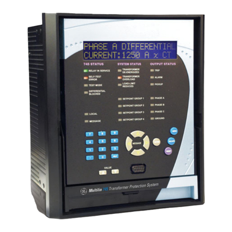
GE SPM Series User manual

SPM
SYNCHRONOUS MOTOR PROTECTION
AND CONTROL
Instruction Manual
Software Revision: 210.000
Manual P/N: 1601-0072-A6
Copyright © 2001 GE Power Management
GE Power Management
215 Anderson Avenue, Markham, Ontario
Canada L6E 1B3
Tel: (905) 294-6222 Fax: (905) 294-8512
Internet: http://www.GEindustrial.com/pm Manufactured under an
ISO9001 Registered system.
g
GE Power Managemen
t


These instructions do not purport to cover all details or variations in equipment nor provide for every possibl
e
contingency to be met in connection with installation, operation, or maintenance. Should further information b
e
desired or should particular problems arise which are not covered sufficiently for the purchaser’s purpose, th
e
matter should be referred to the General Electric Company.
To the extent required the products described herein meet applicable ANSI, IEEE, and NEMA standards; bu
t
no such assurance is given with respect to local codes and ordinances because they vary greatly.


GE Power Management SPM Synchronous Motor Protection & Control
i
TABLE OF CONTENTS
1. INTRODUCTION 1.1 OVERVIEW
1.1.1 GENERAL DESCRIPTION ........................................................................ 1-1
1.1.2 FUNCTIONAL OVERVIEW........................................................................ 1-1
1.2 ORDERING
1.2.1 ORDER CODES ........................................................................................ 1-3
1.2.2 ACCESSORIES......................................................................................... 1-3
1.3 SPECIFICATIONS
1.3.1 SPM SPECIFICATIONS............................................................................ 1-4
2. INSTALLATION 2.1 OVERVIEW
2.1.1 DESCRIPTION .......................................................................................... 2-1
2.1.2 ELEMENTS OF A SYNCHRONOUS MOTOR CONTROLLER.................2-1
2.2 MECHANICAL INSTALLATION
2.2.1 UNPACKING THE SPM............................................................................. 2-2
2.2.2 REMOVING THE DRAWOUT RELAY....................................................... 2-2
2.2.3 INSERTING THE DRAWOUT RELAY....................................................... 2-2
2.2.4 MOUNTING THE SPM .............................................................................. 2-2
2.2.5 SPM MOUNTING ACCESSORIES............................................................ 2-2
2.3 ELECTRICAL INSTALLATION
2.3.1 DESCRIPTION .......................................................................................... 2-4
2.3.2 GROUNDING............................................................................................. 2-6
2.3.3 FIELD AND EXCITER VOLTAGE INPUTS ............................................... 2-6
2.3.4 RELAY OUTPUTS..................................................................................... 2-6
2.3.5 CURRENT TRANSFORMER INPUT......................................................... 2-6
2.3.6 POWER FACTOR OUTPUT...................................................................... 2-6
2.3.7 DC FIELD CURRENT INPUT....................................................................2-6
2.3.8 EXCITER VOLTAGE OUTPUT MONITOR................................................ 2-6
2.3.9 POWER FACTOR REGULATION OUTPUT ............................................. 2-7
2.3.10 CONTROL VOLTAGE ............................................................................... 2-7
2.3.11 EXTERNAL VOLTAGE PF REFERENCE................................................. 2-7
2.3.12 RS485 COMMUNICATIONS PORT .......................................................... 2-8
3. SYNCHRONOUS MOTOR
APPLICATIONS 3.1 OVERVIEW
3.1.1 GENERAL.................................................................................................. 3-1
3.2 COLLECTOR-RING MOTORS
3.2.1 STARTING AND SYNCHRONIZING......................................................... 3-5
3.2.2 RELUCTANCE TORQUE SYNCHRONIZING........................................... 3-6
3.2.3 STARTING PROTECTION ........................................................................ 3-7
3.2.4 REDUCED VOLTAGE STARTING............................................................ 3-8
3.2.5 POWER FACTOR (PULL-OUT) PROTECTION...................................... 3-10
3.2.6 POWER FACTOR OPERATION ............................................................. 3-11
3.2.7 CONTROLLER ACTION DURING PULL-OUT........................................ 3-12
a RESYNC MODE...................................................................................... 3-12
b RIDE-THRU MODE ................................................................................. 3-12
3.2.8 EFFECT OF VOLTAGE DIPS ON MOTOR POWER FACTOR .............. 3-13
3.2.9 POWER FACTOR DETECTION & INDICATION – OVERHAULING LOAD 3-
15
3.2.10 POWER FACTOR REGULATION........................................................... 3-16
3.3 BRUSHLESS CONTROLLER
3.3.1 DESCRIPTION ........................................................................................ 3-17

ii
SPM Synchronous Motor Protection & Control GE Power Management
TABLE OF CONTENTS
3.3.2 BRUSHLESS MOTOR REVIEW..............................................................3-17
3.3.3 STARTING THE BRUSHLESS MOTOR .................................................3-18
3.3.4 STALL PROTECTION ............................................................................. 3-19
3.3.5 POWER FACTOR (PULL-OUT) PROTECTION...................................... 3-19
3.3.6 POWER FACTOR REGULATION ........................................................... 3-19
4. USER INTERFACE 4.1 SPMPC SOFTWARE
4.1.1 DESCRIPTION .......................................................................................... 4-1
4.1.2 SPMPC INSTALLATION............................................................................ 4-2
4.1.3 CONFIGURATION.....................................................................................4-3
4.1.4 CREATING A NEW SETPOINT FILE........................................................ 4-4
4.1.5 EDITING A SETPOINT FILE ..................................................................... 4-5
4.1.6 LOADING SETPOINTS FROM A FILE......................................................4-6
4.1.7 UPGRADING SETPOINT FILES TO A NEW REVISION..........................4-7
4.1.8 PRINTING SETPOINTS & ACTUAL VALUES...........................................4-8
4.1.9 TRENDING ................................................................................................ 4-9
4.2 KEYPAD INTERFACE
4.2.1 DESCRIPTION ........................................................................................ 4-10
4.2.2 CHANGING SETPOINTS ........................................................................ 4-11
4.2.3 CHANGING CALIBRATION VALUES ..................................................... 4-12
4.2.4 CHANGING CONFIGURATIONS............................................................4-13
4.2.5 VIEWING & CHANGING STATUS MODE PARAMETERS.....................4-14
4.2.6 ALTERNATE MENU OPERATION..........................................................4-14
5. SETPOINTS 5.1 OVERVIEW
5.1.1 DESCRIPTION .......................................................................................... 5-1
5.2 SETPOINTS MENU
5.2.1 POWER FACTOR TRIP ............................................................................ 5-2
5.2.2 POWER FACTOR DELAY......................................................................... 5-2
5.2.3 POWER FACTOR SUPRESSION............................................................. 5-2
5.2.4 POWER FACTOR MODE.......................................................................... 5-3
5.2.5 FIELD APPLICATION RELAY DELAY ......................................................5-3
5.2.6 FIELD CONTACTOR AUXILIARY RELAY DELAY.................................... 5-3
5.2.7 AC CT PRIMARY RATING ........................................................................ 5-4
5.2.8 MOTOR FULL LOAD AMPS...................................................................... 5-4
5.2.9 MOTOR LOCKED ROTOR AMPS.............................................................5-4
5.2.10 SYNCHRONOUS SLIP.............................................................................. 5-5
5.2.11 STALL TIME .............................................................................................. 5-5
5.2.12 RUN TIME.................................................................................................. 5-5
5.2.13 DIRECT CURRENT CT PRIMARY RATING.............................................5-6
5.2.14 FIELD OVERTEMPERATURE (HIGH FIELD OHMS) PROTECTION.......5-7
5.2.15 FIELD UNDERCURRENT ......................................................................... 5-8
5.2.16 FIELD UNDERCURRENT DELAY.............................................................5-8
5.2.17 FIELD UNDERVOLTAGE.......................................................................... 5-8
5.2.18 FIELD UNDERVOLTAGE DELAY.............................................................5-9
5.2.19 INCOMPLETE SEQUENCE DELAY..........................................................5-9
5.3 OPTIONAL POWER FACTOR REGULATION SETPOINTS
5.3.1 DESCRIPTION ........................................................................................ 5-10
5.3.2 POWER FACTOR REGULATOR ............................................................5-10
5.3.3 REGULATOR GAIN.................................................................................5-10
5.3.4 STABILITY............................................................................................... 5-10
5.3.5 REGULATOR OUTPUT LIMIT................................................................. 5-11

GE Power Management SPM Synchronous Motor Protection & Control
iii
TABLE OF CONTENTS
5.3.6 FLOOR VOLTS........................................................................................ 5-11
5.4 CONFIGURATIONS MENU
5.4.1 MOTOR TYPE......................................................................................... 5-12
5.4.2 LINE FREQUENCY ................................................................................. 5-12
5.4.3 POWER FACTOR REFERENCE ............................................................ 5-12
5.4.4 RTU ADDRESS....................................................................................... 5-12
5.4.5 BAUD RATE ............................................................................................ 5-12
5.4.6 PARITY.................................................................................................... 5-12
5.4.7 TURNAROUND ....................................................................................... 5-13
5.4.8 STATUS MODE....................................................................................... 5-13
5.4.9 PASSWORD............................................................................................ 5-13
5.5 CALIBRATION MENU
5.5.1 FULL-SCALE EXCITER DC VOLTAGE .................................................. 5-14
5.5.2 FULL-SCALE EXCITER DC AMPS......................................................... 5-14
5.5.3 FULL-SCALE MOTOR AC AMPS............................................................ 5-14
6. ACTUAL VALUES 6.1 DISPLAY SCROLLING
6.1.1 DESCRIPTION .......................................................................................... 6-1
6.2 STATUS
6.2.1 MOTOR RUNNING HOURS...................................................................... 6-2
6.2.2 INCOMPLETE SEQUENCE TRIP COUNTER ..........................................6-2
6.2.3 FIELD LOSS TRIP COUNTER.................................................................. 6-2
6.2.4 PULL-OUT TRIP COUNTER..................................................................... 6-2
6.2.5 RESYNCRONIZATION ATTEMPTS TRIP COUNTER.............................. 6-2
6.2.6 MISSING EXTERNAL PF VOLTAGE REFERENCE COUNTER.............. 6-2
6.2.7 CHECK EXCITER TRIP COUNTER.......................................................... 6-3
6.2.8 POWER FACTOR TRIP COUNTER.......................................................... 6-3
6.2.9 SQUIRREL CAGE TRIP COUNTER ......................................................... 6-3
6.2.10 FIELD OVERVOLTAGE TRIP COUNTER.................................................6-3
7. TESTING AND
TROUBLESHOOTING 7.1 START-UP PROCEDURE
7.1.1 INSPECTION............................................................................................. 7-1
7.1.2 SPM TEST CHECKS................................................................................. 7-1
a STANDBY MODE...................................................................................... 7-1
b TEST MODE.............................................................................................. 7-1
7.1.3 START-UP DESCRIPTION ....................................................................... 7-2
7.2 DISPLAY AND MESSAGES
7.2.1 DISPLAY.................................................................................................... 7-3
7.2.2 SPM MESSAGES...................................................................................... 7-3
7.3 REGULATOR TUNE-UP
7.3.1 INSTRUCTIONS........................................................................................ 7-5
7.4 TROUBLESHOOTING
7.4.1 TROUBLESHOOTING GUIDE .................................................................. 7-6
7.5 PROGRAMMING
7.5.1 PROGRAMMING EXAMPLE..................................................................... 7-8
7.6 DOs AND DON’Ts
7.6.1 DOs.......................................................................................................... 7-12
7.6.2 DON'Ts .................................................................................................... 7-12

iv
SPM Synchronous Motor Protection & Control GE Power Management
TABLE OF CONTENTS
7.7 FREQUENTLY ASKED QUESTIONS
7.7.1 SPM FAQ................................................................................................. 7-13
7.8 REVISION HISTORY
7.8.1 FIRMWARE ............................................................................................. 7-15
7.8.2 SUMMARY............................................................................................... 7-16
8. ACCESSORIES 8.1 VOLTAGE DIVIDER NETWORK
8.1.1 GE POWER MANAGEMENT VDN............................................................8-1
8.1.2 GE MEBANE VDN.....................................................................................8-2
8.2 FIELD CURRENT CALIBRATION MODULE
8.2.1 GE POWER MANAGEMENT MODULE.................................................... 8-3
8.3 DC CURRENT TRANSFORMER
8.3.1 DESCRIPTION .......................................................................................... 8-5
9. MODBUS
COMMUNICATIONS 9.1 IMPLEMENTATION
9.1.1 MODBUS PROTOCOL.............................................................................. 9-1
9.1.2 PERFORMANCE REQUIREMENTS......................................................... 9-1
9.1.3 SETPOINTS............................................................................................... 9-1
9.1.4 EXECUTE OPERATION COMMAND CODES (COIL NUMBERS) ...........9-1
9.2 MEMORY MAPPING
9.2.1 MODBUS MEMORY MAP ......................................................................... 9-2
9.2.2 FORMAT CODES...................................................................................... 9-7
10. FUNCTIONAL TESTS 10.1 INTRODUCTION
10.1.1 DESCRIPTION ........................................................................................ 10-1
10.2 COLLECTOR-RING MOTOR FIELD APPLICATION TEST
10.2.1 SETUP..................................................................................................... 10-2
10.2.2 RELAY PROGRAMMING ........................................................................ 10-2
a CONFIGURATIONS ................................................................................ 10-2
b SETPOINTS............................................................................................. 10-2
10.2.3 TEST........................................................................................................10-2
10.3 COLLECTOR-RING MOTOR POWER FACTOR TEST
10.3.1 SETUP..................................................................................................... 10-3
10.3.2 RELAY PROGRAMMING ........................................................................ 10-3
a CONFIGURATIONS ................................................................................ 10-3
b SETPOINTS............................................................................................. 10-3
10.3.3 TEST........................................................................................................10-3
10.4 COLLECTOR-RING MOTOR POWER FACTOR TRIP TEST
10.4.1 SETUP..................................................................................................... 10-4
10.4.2 RELAY PROGRAMMING ........................................................................ 10-4
a CONFIGURATIONS ................................................................................ 10-4
b SETPOINTS............................................................................................. 10-4
10.4.3 TEST........................................................................................................10-4
10.5 BRUSHLESS MOTOR FIELD APPLICATION TEST
10.5.1 SETUP..................................................................................................... 10-5
10.5.2 RELAY PROGRAMMING ........................................................................ 10-5
a CONFIGURATIONS ................................................................................ 10-5
b SETPOINTS............................................................................................. 10-5

GE Power Management SPM Synchronous Motor Protection & Control
v
TABLE OF CONTENTS
10.5.3 TEST........................................................................................................ 10-5
10.6 BRUSHLESS MOTOR POWER FACTOR TEST
10.6.1 SETUP..................................................................................................... 10-6
10.6.2 RELAY PROGRAMMING........................................................................ 10-6
a CONFIGURATIONS ................................................................................ 10-6
b SETPOINTS............................................................................................. 10-6
10.6.3 TEST........................................................................................................ 10-6
10.7 BRUSHLESS MOTOR POWER FACTOR TRIP TEST
10.7.1 SETUP..................................................................................................... 10-7
10.7.2 RELAY PROGRAMMING........................................................................ 10-7
a CONFIGURATIONS ................................................................................ 10-7
b SETPOINTS............................................................................................. 10-7
10.7.3 TEST........................................................................................................ 10-7
10.8 AC CURRENT METERING AND PULL-OUT TEST
10.8.1 SETUP..................................................................................................... 10-8
10.8.2 RELAY PROGRAMMING........................................................................ 10-8
a CONFIGURATIONS ................................................................................ 10-8
b SETPOINTS............................................................................................. 10-8
10.8.3 TEST........................................................................................................ 10-8
10.9 EXCITER / FIELD VOLTAGE METERING TEST
10.9.1 SETUP..................................................................................................... 10-9
10.9.2 RELAY PROGRAMMING........................................................................ 10-9
a CONFIGURATIONS ................................................................................ 10-9
b SETPOINTS............................................................................................. 10-9
10.9.3 TEST........................................................................................................ 10-9
10.10 EXCITER / FIELD CURRENT METERING TEST
10.10.1 SETUP................................................................................................... 10-10
10.10.2 RELAY PROGRAMMING...................................................................... 10-10
a CONFIGURATIONS .............................................................................. 10-10
b SETPOINTS........................................................................................... 10-10
10.10.3 TEST...................................................................................................... 10-10
A. COMMISSIONING A.1 COMMISSIONING
A.1.1 COLLECTOR-RING SETTINGS................................................................A-1
A.1.2 BRUSHLESS SETTINGS..........................................................................A-2
B. FIGURES AND TABLES B.1 FIGURES AND TABLES
B.1.1 LIST OF FIGURES ....................................................................................B-1
B.1.2 LIST OF TABLES.......................................................................................B-2
C. WARRANTY C.1 WARRANTY
C.1.1 WARRANTY ..............................................................................................C-1

vi
SPM Synchronous Motor Protection & Control GE Power Management
TABLE OF CONTENTS

GE Power Management SPM Synchronous Motor Protection & Control 1-
1
1 INTRODUCTION 1.1 OVERVIEW
1
1 INTRODUCTION 1.1 OVERVIEW 1.1.1 GENERAL DESCRIPTION
The SPM controls starting, synchronizing, and protection of collector-ring and brushless type synchronous
motors.
The SPM control functions for starting synchronous motors include accurate sensing of motor speed and rotor
angle, allowing the unit to apply excitation at optimum speed and angle. This permits closer matching of the
motor to the load. Optimum application of excitation also reduces power system disturbance, which occurs
when the motor goes through a complete slip cycle with the field energized. In addition, the SPM can take
advantage of the extended stall time of a reduced voltage start. It also responds with the proper application of
excitation in the event that the motor synchronizes on reluctance torque.
The SPM provides the functions necessary to protect the motor during startup and in the event of asynchro-
nous operation. During startup and restarting, the SPM prevents overheating of the cage winding. To protect
against asynchronous operation, the motor power factor is monitored. Two modes of pull-out protection can trip
the motor if resynchronization does not occur after a programmed time delay. Motor run time and the number
and type of trips are recorded.
The SPM has an optional power factor regulator containing five adjustable setpoints that can be changed while
the motor is running for convenient regulator tune-up.
A backlit LCD display and keys allow user configurable setting ranges to meet many applications. The unit
comes in a compact S1 drawout case.
The SPM can be applied as part of a complete synchronous motor controller. This consists of four parts. A
main device switches the motor on and off the power system. Multifunction digital relays (such as the GE
Power Management 469 Motor Management Relay) provide stator protection. DC field protection and control
are provided by the SPM. The field contactor and field discharge resistor completes the control assembly.
1.1.2 FUNCTIONAL OVERVIEW
The DC portion of the synchronous motor (rotor assembly) is protected and controlled using a drawout micro-
processor based multifunction relay. The relay is adaptable to either collector-ring or brushless type synchro-
nous motors. Protection features include all of the following:
• Cage winding and stall protection during start
• Lockout feature to protect a hot rotor after an incomplete start
• Incomplete sequence trip due to failed acceleration
• Automatic acceleration time adjustment for reduced voltage starting
• Power factor (pull-out) trip with auto resynchronizing feature
• Loss of DC field current trip
• Loss of DC field voltage trip
• Field winding overtemperature trip
After a successful start, the relay automatically applies the DC field to the rotor at a prescribed slip and slip
angle to minimize mechanical stresses to the shaft as well as minimizes possible electrical transients to the
power system. This is achieved by a dedicated output to close the DC field contactor. The relay is also capable
of reluctance torque synchronizing (collector-ring machines only).
A dedicated output is provided in the relay to enable the loading of the motor following the DC field application
and unloading of the motor following a trip and/or loss of synchronization (pole slipping).
Control of an SCR type excitation system by means of an analog output to maintain power factor (PF regula-
tion) is available as an option.

1-
2
SPM Synchronous Motor Protection & Control GE Power Management
1.1 OVERVIEW 1 INTRODUCTION
1The man-machine interface (MMI) consists of a backlit alphanumeric display and a keypad to accommodate
relay programming as well as viewing actual motor parameters which comprise:
• AC stator current
• Power factor
• DC field current
• DC field voltage
• DC field resistance
• Running time meter (RTM)
Statistical data includes number and type of trips.
The SPM performs a complete system check prior to starting the motor.
Figure 1–1: SINGLE LINE DIAGRAM
701767A9.CDR
MOTOR
LOAD
AC BUS
CLUTCH
COUPLING
DC SUPPLY
27 26F 95
96
56
95
48
94
86
94
48
55
SPM
Stator
Protection
(469)
Calibrator
DC
CT
37
50
IAC
VDC
IDC
VAC
ANSI DEVICE NUMBERS
Field overtemperature
Undervoltage
Undercurrent or underpower
Incomplete sequence
Instantaneous overcurrent
Power factor
Field application
Lock out
Tripping
Reluctance torque sync. / resync.
Autoloading relay
26F
27
37
48
50
55
56
86
94
95
96

GE Power Management SPM Synchronous Motor Protection & Control 1-
3
1 INTRODUCTION 1.2 ORDERING
1
1.2 ORDERING 1.2.1 ORDER CODES
The SPM has all features built into the standard relay and programmable by the user to fit the specific applica-
tion. The only option in the order code is for Power Factor Regulation. Some of the standard features require
an optional external hardware package that must be ordered in addition to the relay itself. These separate
packages are explained in the following section.
1.2.2 ACCESSORIES
PG2SPM: External hardware package for overtemperature and current loss protection up to 200 A
(includes 1-DCCT200 & 1-CM)
PG4SPM: External hardware package for overtemperature and current loss protection up to 400 A
(includes 1-DCCT400 or DCCT500 and 1-CM)
MPSPM: Mounting panel to retrofit existing µSPM cutouts for SPM
SPM
Base Unit SPM |Standard starting and protection relay with VDN board
Configuration PF Power Factor regulation option. Used on motors with SCR exciter
(not recommended for brushless applications)

1-
4
SPM Synchronous Motor Protection & Control GE Power Management
1.3 SPECIFICATIONS 1 INTRODUCTION
11.3 SPECIFICATIONS 1.3.1 SPM SPECIFICATIONS
PHASE CURRENT INPUTS
CT Primary: 5 to 2000 A
CT Secondary: 5 A
Conversion Range: 0.05 to 6 ×CT
Frequency: 50 / 60 Hz
Accuracy: at <2 ×CT: ±0.5% of 2 ×CT true RMS
at ≥ 2 ×CT: ±1% of 6 ×CT true RMS
FIELD CURRENT INPUTS
CT Primary: 5 to 1000 A
Conversion Range: 0.05 to 1 ×CT
Accuracy: ±2%
EXCITER VOLTAGE INPUTS
Conversion: 0 to 350 V DC (prior to VDN)
Accuracy: ±1%
POWER FACTOR
Range: 0.01 to 1 to –0.01
Time Delay: 0.1 to 10 seconds
Accuracy: ±5%
SWITCH INPUTS (MX & NX)
Type : Dr y con ta ct
Internal Interrogation Voltage: 85 to 265 V AC (control voltage)
PF ANALOG OUTPUT
Type: Active
Output: 0 to 10 V DC max. at RL≥1 KΩ(min. load)
Accuracy: ±10% (0.1 V)
Isolation: 36 V pk
CONTROL VOLTAGE
Input: 85 to 265 V AC at 48 to 60 Hz
Power: 10 VA nominal
Holdup: 100 ms typical at 120 V AC
RELAY CONTACT
Type: FAR, TRP Form A
FCX Form C
Rated Load: 10 A AC continuous NEMA A300
1 A DC continuous NEMA R300
Break: 10 A at 250 V AC or 30 V DC
Max. Operating Voltage: 250 V AC
ENVIRONMENT
Humidity: 0 to 95% non-condensing
Operating Temp.: –20°C to +70°C
Storage Temp.: –40°C to +85°C
TYPE TESTS
Dielectric Strength: Per IEC 255-5 and ANSI/IEEE C37.90
2.0 kV for 1 min. from relays, CTs, VTs
power supply to Safety Ground
Insulation
Resistance: IEC255-5 500 VDC, from relays, CTs, VTs
power supply to Safety Ground
Transients: ANSI C37.90.1 Oscillography (2.5kV/1MHz)
ANSI C37.90.1 Fast Rise (5kV/10ns)
Ontario Hydro A-28M-82
IEC255-4 Impulse/High Frequency Disturbance,
Class III Level
Impulse Test: IEC 255-5 0.5J 5kV
EMI: C37.90.2 Electromagnetic Interference at
150 MHz and 450 MHz, 10V/m
Static: IEC801-2 Static Discharge
Vibration: Sinusoidal Vibration 8.0g for 72 hrs.
CERTIFICATION
UL: UL listed
CSA: CSA approved
PHYSICAL
Shipping Box: 12.50" ×10.50" ×9.75" (L ×H ×D)
318 mm ×267 mm ×248 mm (L ×H ×D)
Ship Weight: 14.25 lb. / 6.45 kg
Specifications subject to change without notice

GE Power Management SPM Synchronous Motor Protection & Control 2-
1
2 INSTALLATION 2.1 OVERVIEW
2
2 INSTALLATION 2.1 OVERVIEW 2.1.1 DESCRIPTION
The SPM can be incorporated in synchronous motor control equipment as a complete controller (including an
AC power-switching device for the motor starter) or as a field panel (AC power switching supplied by other
device).
2.1.2 ELEMENTS OF A SYNCHRONOUS MOTOR CONTROLLER
A complete synchronous-motor controller has the ability to switch the motor on to and off of the power system
and protect the motor from damage that can occur if the motor is running in an abnormal condition such as out-
of-synchronization.
A complete synchronous-motor controller consists of a motor starter and switching device (typically a contac-
tor) which controls the main power to the motor. In addition, protective relaying is provided for both the stator
and the rotor (such as a 469/SPM combination). Controls for starting and stopping the motor (start-stop push-
buttons) are also included. Indicating and metering devices such as line ammeters are supplied if not included
in the relays. All of these features are common with motor controllers of all types.
Figure 2–1: EXPLODED VIEW OF THE SPM

2-
2
SPM Synchronous Motor Protection & Control GE Power Management
2.2 MECHANICAL INSTALLATION 2 INSTALLATION
2
2.2 MECHANICAL INSTALLATION 2.2.1 UNPACKING THE SPM
When the SPM is shipped separately, carefully unpack the module and report any observable damage or miss-
ing components to the carrier and to GE Power Management. All included parts are shown in Figure 2–1:
EXPLODED VIEW OF THE SPM on page 2–1.
2.2.2 REMOVING THE DRAWOUT RELAY
1. Remove the faceplate assembly carefully by pushing in on the quick release tabs on the front of the SPM
and pulling the faceplate assembly forward. Once the faceplate has pivoted forward, gently lower the face-
plate so that it clears the tabs on the bottom of the frame.
DO NOT let the faceplate assembly dangle from the connecting wires.
2. Carefully disconnect the ribbon cable from the cradle assembly.
3. Remove the paddle and open the top and bottom locking tabs. The relay can now be removed from the
case.
2.2.3 INSERTING THE DRAWOUT RELAY
1. Slide the relay into the case and close the top and bottom locking tabs.
2. Insert the paddle into the opening at the bottom of the relay.
3. Carefully re-connect the ribbon cable to the cradle assembly.
DO NOT shift or skew the ribbon connector.
4. Re-mount the faceplate assembly to the case from the front panel. Slide the faceplate onto the tabs on the
bottom of the frame and then pivot it up into position over the quick release tabs. The faceplate should
gently snap into place.
2.2.4 MOUNTING THE SPM
Mounting the SPM requires careful attention to the following instructions.
DE-ENERGIZE ALL EXISTING EQUIPMENT BEFORE INSTALLING NEW EQUIPMENT.
1. Remove the relay from the case.
2. Prepare the mounting hole in the panel to dimensions shown in Figure 2–2: PHYSICAL DIMENSIONS.
3. Slide the case into the panel from the front.
4. Install the four mounting screws from the rear of the panel. The case is now securely mounted and ready
for panel wiring.
2.2.5 SPM MOUNTING ACCESSORIES
See Chapter 8: ACCESSORIES for physical dimensions and mounting requirements.
NOTE
NOTE
CAUTION

GE Power Management SPM Synchronous Motor Protection & Control 2-
3
2 INSTALLATION 2.2 MECHANICAL INSTALLATION
2
Figure 2–2: PHYSICAL DIMENSIONS
SPM Sync. Protection/Control

2-
4
SPM Synchronous Motor Protection & Control GE Power Management
2.3 ELECTRICAL INSTALLATION 2 INSTALLATION
2
2.3 ELECTRICAL INSTALLATION 2.3.1 DESCRIPTION
Wire the SPM using one of the following wiring diagrams (one each for brushless, collector ring, and brushless
and collector ring). Pay particular attention to the CT and PT inputs. These inputs must be connected as shown
below for proper power factor protection.
Figure 2–3: TYPICAL WIRING DIAGRAM
USED FOR SEPARATELY
SUPPLIED POWER FACTOR
REFERENCE VOLTAGE
(OPTIONAL CONNECTION)
STOP START
MAIN
AUXILIARY
M
M
EXCITER
CONTACTOR
M
OL
SUPPLY
C
B
A
TYPICAL COLLECTOR RING MOTOR CONNECTION
T1
PHASE C T3
T2
(+)
F1
FIELD
FIELD
DISCHARGE
RESISTOR
FIELD
CONTACTOR
FC
FC
EXCITER
V+
EXCITER
V-
CM
8
CM
7
FC
F2
(R1)
(F2)
(E+) (V+)
(E-) (V-)
+
-
VOLTAGE DIVIDER
NETWORK (VDN)
A17
A16
N+
N-
POWER
FACTOR
OUTPUT
V
1
V
2
B9
G1
B8
B10
CONTROL
POWER
REF. VOLT.
CHASSIS GROUND
FILTER GROUND
A21
A20
V+
V-
A18
A19
V+
F
F
E
E
V-
EXCITER/FIELD
VOLTAGE
FIELD
CURRENT
OPTIONAL
REF. VOLT.
A5
A4
V
V
A24
A25
I- I+
EE
1EXT
2EXT
REDUCED
VOLTAGE
DIGITAL INPUTS
RS485
A11
A12
A1
MX
MX1
-
MX
MONITOR
A9
A2
NX2
+
A10
A3
NX1
COMM
GND
SYNC
MOTOR
PF ANALOG OUTPUT OR
PF REG CONTROL SIG
OUTPUT (IF PF
REGULATOR OPTION)
ON REDUCED VOLTAGE
STARTERS, REMOVE
JUMPER AND CONNECT
A NO. AUX CONTACT
FROM THE FINAL STEP
CONTACTOR HERE.
DCCTDCCT
V+V+
V-V-
RM
EXCITER
TO EXCITER
POWER SUPPLY
TO PLC
OR COMPUTER
BRUSHLESS & COLLECTOR RING - 701756AN.CDR
COLLECTOR RING - 701751.DWG
BRUSHLESS - 701753.DWG
()
B1
I2S I2T
PHASE CURRENT INPUT
B2
B4
B3
I3T
I3S
FC
FIELD
CONTACTOR
RM
MX
NOTES:
1) Relays shown with no control power applied to relay
2) Trip Relay closed during normal operation
*
FIELD CURRENT CALIBRATION MODULE
DIRECT CURRENT CT
MAIN CONTACTOR
OVERLOAD RELAY
MOTOR TERMINALS
OPTIONAL ACCESSORIES
CM
DCCT
M
OL
T1, T2, T3
NOMENCLATURE
FIELD CURRENT
CALIBRATION
MODULE (CM)
240 VAC
120 VAC
65
2
1
4
3
8
7
FIELD CONTACTOR
TYPICAL BRUSHLESS MOTOR CONNECTION
T1
T3
T2
EF1
FIELD
FC FC
R
EF2
(E+) (V+)
(E-) (V-)
VOLTAGE DIVIDER
NETWORK (VDN)
SYNC
MOTOR
A18
A19
V+
F
F
V-
EXCITER/FIELD
VOLTAGE
A21
A20
V+
V-
E
E
A
B
C
B1
PHASE CURRENT INPUT
B2
B4
I2T
B3
I2S
I3S
I3T
DCCT
A13
A14
A15
COM
FCX
N/C
FIELD
CONTACTOR AUX.
(FCX)
A22
A23
*
TRIP
OUTPUT RELAYS
FCX
N/O
TRIP1
TRIP2
A6
A7
FIELD
APPLICATION
(FAR)
FAR 1
FAR 2
M
SPM
GE POWER MANAGEMENT
SPM
GE POWER MANAGEMENT

GE Power Management SPM Synchronous Motor Protection & Control 2-
5
2 INSTALLATION 2.3 ELECTRICAL INSTALLATION
2
Figure 2–4: PANEL AND TERMINAL LAYOUT
AC Amps
Power Factor
DC Amps
DC Volts
(Exciter) Field Ohms
Power Factor Trip
Power Factor Trip Delay
Power Factor Suppression
FCX Delay
Power Factor Mode
FAR Delay
DISPLAY FUNCTIONS
DISPLAY SCROLL SETPOINT SCROLL
CONTRAST
AC CT Rating
Full Load Amps
Locked Rotor Amps
Sync. Slip
Run Time
Stall Time
DC CT Primary
High (Exciter) Field Ohms
(Exciter) Field Amps
(Exciter) Field Volts
Incomplete Sequence Delay
Regulator Power Factor
Regulator Gain
Regulator Stability
Regulator Output
Regulator Floor Volts
Items in and white come standard.green
Items in green are motor type dependent.
Items in yellow are optional.
1
1
2
2
3
3
4
4
5
5
6
6
7
7
8
8
9
9
10
10
11
11
12
12
13
13
14
14
15
15
16
16
17
17
18
18
19
19
20
20
21
21
22
22
23
23
24
24
25
25
26
26
27
27
28
28
FRONT VIEW
REAR VIEW
701750AF.CDR
Used to remove display for easy
access to drawout.
Lightens or darkens display.
Hides menu when not in use.
CONTRAST DIAL
PULLDOWN DOOR
85 to 265VAC.
CONTROL POWER
A wire lead seal can be used to
prevent unauthorized removal
of relay.
LOCKING PROVISION
Menu of all accessible setpoints
and actual values for easy reference.
Compact S1 rugged metal/bakelite
case. Fits standard cutout.
2 Phase current inputs.
Accept #8 wire.
DISPLAY FUNCTION MENU
S1 CASE
MOTOR LINE CURRENT
QUICK RELEASE TABS
A
B
A
1
1 2 3 45678910
I2S I2T I3S I3T
2
3
4
5
6
7
8
9
10
11
12
13
14
15
16
17
18
19
20
21
22
23
24
25
26
27
28
RS485-
RS485+
RS485 GND
NX2
NX1
MX1
N-
N+
V+
F
V-
F
V-
E
V+
E
I-
E
NC
NC
NC
I+
E
NC
SPM Sync. Protection/Control
SCROLL
ENTER
TRIP: Normally open,
failsafe trip relay.
FAR: Field application
relay.
FCX: Autoloading of the
motor.
EXCITER: Exciter voltage
inputs. Connected via
DCCT and CM.
REDUCED VOLTAGE:
Contact input for
reduced voltage starting.
Motor "ON" input.
Exciter current input.
Power Factor reference
voltage (for seperately
powered option).
POWER FACTOR:
0-10VDC analog signal.
FIELD: DC field voltage
input.
RELAYS
INPUTS
OUTPUTS
TERMINAL BLOCK A
Used to enter or exit the different
modes of the SPM. These are
Standby, Test, Statistics and
Programming modes.
GE KEY
Used to make a selection or acts
as an enter key.
ENTER KEY
Used to scroll through the various
menus and change setpoint
parameter values.
SCROLL KEYS
Back lit 32 character display for
setpoints, actual values and status.
Programmable auto scan sequence
for unattended operation.
LCD DISPLAY
V
1
FILTER
GND
V
2
V
2EXT
V
1EXT
FAR2
FAR1
MX
FCX N/O
FCX COM
FCX N/C
TRP2
TRP1
Motor Hours
ISP Trip Ctr
FLP Trip Ctr
PO Trip Ctr
Resync Ctr
NO V Trp Ctr
Exc Trip Ctr
PF Trip Ctr
SCP Trip Ctr
FOT Trip Ctr
STAT SCROLL

2-
6
SPM Synchronous Motor Protection & Control GE Power Management
2.3 ELECTRICAL INSTALLATION 2 INSTALLATION
2
2.3.2 GROUNDING
The SPM relay must be solidly grounded to a suitable system ground. Extensive filtering and transient protec-
tion has been built into the SPM to ensure proper and reliable operation in harsh industrial environments.
Proper grounding of the chassis ground terminal is critical to en-sure safety and filtering.
2.3.3 FIELD AND EXCITER VOLTAGE INPUTS
The field voltage inputs (VF+ and VF–) and exciter voltage inputs (VE+ and VE–) are connected to the relay
via the supplied voltage divider network (VDN).
DO NOT ATTEMPT TO START THE MOTOR WITHOUT THE EXTERNAL RESISTOR ASSEMBLY
WIRED. SEVERE DAMAGE TO THE SPM MAY RESULT IF THE EXTERNAL RESISTOR ASSEM-
BLY IS NOT PROPERLY CONNECTED.
2.3.4 RELAY OUTPUTS
The following is a description of the relay outputs.
1. TRIP: Trip Relay. This relay is normally energized and drops out on loss of power or when the module
senses an abnormal condition.
2. FAR: Field Application Relay. This relay picks up at the proper time to apply DC to the motor field.
3. FCX: Loading Relay. This relay picks up when the motor is fully synchronized and ready to be loaded. It is
controlled by the "FCX Delay" programmable setpoint.
2.3.5 CURRENT TRANSFORMER INPUT
The SPM is designed to work from a five ampere (5 A) current transformer (CT) secondary. The current trans-
former must be connected in the proper motor phase. See Figure 2–3: TYPICAL WIRING DIAGRAM on page
2–4 to determine proper phase. For brushless applications, the SPM requires inputs from two motor phases.
2.3.6 POWER FACTOR OUTPUT
This output is a 0 to 10 V DC signal that corresponds linearly to phase shift, and sinusoidal to motor power fac-
tor. 0 V is zero lagging power factor, 5 V is unity power factor, and 10 V is zero leading power factor.
Calibration: 1 volt change corresponds to an 18° phase shift (not available with power factor regulation). Do not
connect less than 1000 Ωto this output.
2.3.7 DC FIELD CURRENT INPUT
DC field input must be sensed from a separately purchased DCCT (Direct Current, Current Transformer) and
CM (Calibration Module).
2.3.8 EXCITER VOLTAGE OUTPUT MONITOR
The output of the field exciter must be connected to the SPM through a separate resistor when exciter voltage
failure protection and/or exciter voltage display is required.
CAUTION
This manual suits for next models
2
Table of contents
Other GE Power Distribution Unit manuals
Popular Power Distribution Unit manuals by other brands

TRENDnet
TRENDnet TPI-06 user guide

S&C
S&C Remote Supervisory Vista Operation manual

Leviton
Leviton DC Power Distribution Module 48212-DC Product specifications

Trace Engineering
Trace Engineering DC175 - V2.0 manual

Avocent
Avocent Cyclades PM10-15A Specification sheet

Panamax
Panamax POWER360 P360-DOCK instruction manual