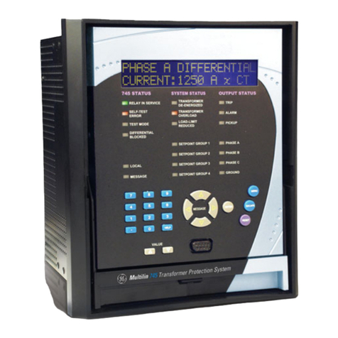
GE AF-600 FP Series User manual

GE Consumer & Industrial
Electrical Distribution
AF-600 FPTM
Fan and Pump Drive
(460V/575V 150HP and above)
Operating Instructions
The instructions do not purport to cover all details or variations in equipment nor to provide for every possible
contingency to be met in connection with installation, operation or maintenance. Should further information be
desired or should particular problems arise which are not covered sufficiently for the purchaser’s purposes, the
matter should be referred to the GE company.
AF-600 FP is a trademark of the General Electric Company.
GE Consumer & Industrial
41 Woodford Avenue
Plainville, CT 06062
www.geelectrical.com/drives
130R0135 MG11U102 *MG11U102* DET-610

Contents
1 How to Read these Operating Instructions
5
Copyright, Limitation of Liability and Revision Rights 5
2 Safety
7
Safety instructions 7
General Warning 7
Before commencing repair work 8
Special conditions 8
Avoid unintended start 9
IT mains 9
3 Electrical Installation
11
Electrical Installation 11
Power Connections 11
Mains connection 23
Fuses 24
Fuse tables 24
Motor Insulation 25
Motor Bearing Currents 26
Control cable routing 26
Electrical Installation, Control Terminals 28
Connection Examples 29
Start/Stop 29
Pulse Start/Stop 29
Electrical Installation - additional 31
Electrical Installation, Control Cables 31
Switches S201, S202, and S801 33
Final Set-up and Test 34
Additional Connections 36
Motor Thermal Protection 36
4 Introduction
37
5 Mechanical Installation
39
How to Get Started 39
Pre-installation 40
Planning the Installation Site 40
Receiving the Frequency Converter 40
Transportation and Unpacking 40
Lifting 42
Mechanical Dimensions 44
AF-600 FP High Power Operating Instructions
1

Rated Power 51
Mechanical Installation 52
Terminal locations - Unit Size 4X 54
Terminal Locations - Unit Size 5X 55
Terminal Locations - Unit Sizes 6X 57
Cooling and Airflow 60
Field Installation of Options 64
Installation of Duct Cooling Kit in Rittal Units 64
Installation on pedestal 67
Installation of Mains Shield for frequency converters 69
Panel Options 69
Unit Size 6X Panel Options 69
6 How to operate the frequency converter
71
How to operate the keypad 71
Tips and tricks 78
7 How to Program
81
Quick Menu Mode 83
Macros 88
Parameter List 119
K-## Keypad Set-up 120
F-## Fundamental Parameters 122
E-## Digital In/Outs 123
C-## Frequency Control Functions 125
P-## Motor Data 126
H-## High Perf Parameters 127
AN-## Analog In / Out 129
SP-## Special Functions 130
O-## Options/Comms 131
AO-## Analog I/O Option 132
DN-## DevicNet 133
PB-## Profibus 134
BN-## BACnet 135
ID-## Drive Information 136
DR-## Data Readouts 138
LG-## Logs & I/O Opt. Status 140
AP-## HVAC Appl. Param. 141
FB-## Fire/Bypass Operation 142
T-## Timed Functions 143
CL-## PID Closed Loop 144
XC-## Ext. PID Closed Loop 145
AF-600 FP High Power Operating Instructions
2

PC-## Pump Controller 146
LC-## Logic Controller 147
B-## Braking Functions 148
8 General Specifications
149
9 Warnings and Alarms
161
Fault messages 164
Index
168
AF-600 FP High Power Operating Instructions
3

AF-600 FP High Power Operating Instructions
4
1

1 How to Read these Operating Instructions
1.1.1 Copyright, Limitation of Liability and Revision Rights
This publication contains information proprietary to GE. By accepting and using this manual the user agrees that the information contained herein will be used
solely for operating equipment from GE or equipment from other vendors provided that such equipment is intended for communication with GE equipment over
a serial communication link. This publication is protected under the Copyright laws of Denmark and most other countries.
GE does not warrant that a software program produced according to the guidelines provided in this manual will function properly in every physical, hardware or
software environment.
Although GE has tested and reviewed the documentation within this manual, GE makes no warranty or representation, neither expressed nor implied, with respect
to this documentation, including its quality, performance, or fitness for a particular purpose.
In no event shall GE be liable for direct, indirect, special, incidental, or consequential damages arising out of the use, or the inability to use information contained
in this manual, even if advised of the possibility of such damages. In particular, GE is not responsible for any costs, including but not limited to those incurred as
a result of lost profits or revenue, loss or damage of equipment, loss of computer programs, loss of data, the costs to substitute these, or any claims by third
parties.
GE reserves the right to revise this publication at any time and to make changes to its contents without prior notice or any obligation to notify former or present
users of such revisions or changes.
AF-600 FP High Power Operating Instructions
5
1

1.1.2 Symbols
Symbols used in this manual:
NB!
Indicates something to be noted by the reader.
Indicates a general warning.
Indicates a high-voltage warning.
✮Indicates default setting
1.1.3 Available literature
-Operating Instructions provide the necessary information for getting the frequency converter up and running.
-Design Guide entails all technical information about the frequency converter and customer design and applications.
-Programming Guide provides information on how to program and includes complete parameter descriptions.
GE technical literature is available in print from your local GE Sales Office or online at: www.geelectrical.com/drives
- AF-600 FP Built-in network manuals are available separately.
AF-600 FP High Power Operating Instructions
6
1

2 Safety
2.1.1 High voltage warning
The voltage of the frequency converter is dangerous whenever it is connected to mains. Incorrect installation of the motor or frequency
converter may cause damage to the equipment, serious injury or death. Consequently, it is essential to comply with the instructions in this
manual as well as local and national rules and safety regulations.
2.1.2 Safety instructions
Prior to using functions directly or indirectly influencing personal safety (e.g. Fire Mode or other functions either forcing the motor to stop or
attempting to keep it functioning) a thorough risk analysis and system test must be carried through. The system tests must include testing
failure modes regarding the control signalling (analog and digital signals and serial communication.
• Make sure the frequency converter is properly connected to earth.
• Do not remove mains connections, motor connections or other power connections while the frequency converter is connected to power.
• Protect users against supply voltage.
• Protect the motor against overloading according to national and local regulations.
• The earth leakage current exceeds 3.5 mA.
• The [OFF] key is not a safety switch. It does not disconnect the frequency converter from mains.
2.1.3 General Warning
Warning:
Touching the electrical parts may be fatal - even after the equipment has been disconnected from mains.
Also make sure that other voltage inputs have been disconnected, (linkage of DC intermediate circuit), as well as the motor connection for
kinetic back-up.
Before touching any potentially live parts of the frequency converter, wait at least as follows:
380 - 480 V, 110 - 250 kW, wait at least 20 minutes.
380 - 480 V, 315- 1000 kW, wait at least 40 minutes.
525 - 600 V, 45 - 400 kW, wait at least 20 minutes.
525 - 600 V, 450 - 1000 kW, wait at least 30 minutes.
Shorter time is allowed only if indicated on the nameplate for the specific unit.
Leakage Current
The earth leakage current from the frequency converter exceeds 3.5 mA. According to IEC 61800-5-1 a reinforced Protective Earth connection
must be ensured by means of: a min. 10mm² Cu or 16mm² Al PE-wire or an addtional PE wire - with the same cable cross section as the Mains
wiring - must be terminated separately.
Residual Current Device
This product can cause a D.C. current in the protective conductor. Where a residual current device (RCD) is used for extra protection, only an
RCD of Type B (time delayed) shall be used on the supply side of this product.
Protective earthing of the frequency converter and the use of RCD's must always follow national and local regulations.
AF-600 FP High Power Operating Instructions
7
2

2.1.4 Before commencing repair work
1. Disconnect the frequency converter from mains
2. Disconnect DC bus terminals 88 and 89
3. Wait at least the time mentioned in section General Warning above
4. Remove motor cable
2.1.5 Special conditions
Electrical ratings:
The rating indicated on the nameplate of the frequency converter is based on a typical 3-phase mains power supply, within the specified voltage, current and
temperature range, which is expected to be used in most applications.
The frequency converters also support other special applications, which affect the electrical ratings of the frequency converter.
Special conditions which affect the electrical ratings might be:
• High temperature applications which require de-rating of the electrical ratings
• Marine applications with more severe environmental conditions.
Other applications might also affect the electrical ratings.
Consult the relevant sections in this manual and in the AF-600 FP Design Guide for information about the electrical ratings.
Installation requirements:
The overall electrical safety of the frequency converter requires special installation considerations regarding:
• Fuses and circuit breakers for over-current and short-circuit protection
• Selection of power cables (mains, motor, brake, loadsharing and relay)
• Grid configuration (IT,TN, grounded leg, etc.)
• Safety of low-voltage ports (PELV conditions).
Consult the relevant clauses in these instructions and in the AF-600 FP Design Guide for information about the installation requirements.
2.1.6 Caution
The frequency converter's DC link capacitors remain charged after power has been disconnected. To avoid an electrical shock hazard, dis-
connect the frequency converter from the mains before carrying out maintenance. Before doing service on the frequency converter, wait at
least the amount of time indicated below:
Voltage Power size Min. Waiting Time
380 - 480 V 110 - 250 kW 20 minutes
315 - 1000 kW 40 minutes
525 - 600 V 45 - 400 kW 20 minutes
450- 1000 kW 30 minutes
Be aware that there may be high voltage on the DC link even when the LEDs are turned off.
AF-600 FP High Power Operating Instructions
8
2

2.1.7 Installation at high altitudes (PELV)
Installation at high altitude:
380 - 480 V: At altitudes above 3 km, please contact GE regarding PELV.
525 - 600 V: At altitudes above 2 km, please contact GE regarding PELV.
2.1.8 Avoid unintended start
While the frequency converter is connected to mains, the motor can be started/stopped using digital commands, bus commands, references or via the
keypad.
• Disconnect the frequency converter from mains whenever personal safety considerations make it necessary to avoid unintended start.
• To avoid unintended start, always activate the [OFF] key before changing parameters.
• An electronic fault, temporary overload, a fault in the mains supply, or lost motor connection may cause a stopped motor to start.
2.1.9 IT mains
IT Mains
Do not connect frequency converters with option factory installed A1/B1 RFI filters to mains supplies with a voltage between phase and earth
of more than 440 V for 400 V.
For 400 V IT mains and delta earth (grounded leg), mains voltage may exceed 440 V between phase and earth.
par. SP-50 RFI Filter can be used to disconnect the internal RFI capacitiors from the RFI filter to ground.
2.1.10 Software version and approvals: AF-600 FP Fan & Pump Drive
AF-600 FP
Software version: 2.9.x
This manual can be used with all AF-600 FP frequency converters with software version 2.9x.
The software version number can be seen from par. ID-43 Software Version.
2.1.11 Disposal instruction
Equipment containing electrical components must not be disposed of together with domestic waste.
It must be separately collected with electrical and electronic waste according to local and currently valid legislation.
AF-600 FP High Power Operating Instructions
9
2

AF-600 FP High Power Operating Instructions
10
3

3 Electrical Installation
3.1 Electrical Installation
3.1.1 Power Connections
Cabling and Fusing
NB!
Cables General
All cabling must comply with national and local regulations on cable cross-sections and ambient temperature. Copper (75°C) conductors are recommended.
The power cable connections are situated as shown below. Dimensioning of cable cross section must be done in accordance with the current ratings and local
legislation. See the Specifications section for details.
For protection please see fuse in the tables of the fuse section. Always ensure that proper fusing is made according to local regulation.
NB!
Use a screened/armoured motor cable to comply with EMC emission specifications. For more information, see EMC specifications in the AF-600 FP/Design
Guide.
See section General Specifications for correct dimensioning of motor cable cross-section and length.
AF-600 FP High Power Operating Instructions
11
3

Screening of cables:
Avoid installation with twisted screen ends (pigtails). They spoil the screening effect at higher frequencies. If it is necessary to break the screen to install a motor
isolator or motor contactor, the screen must be continued at the lowest possible HF impedance.
Connect the motor cable screen to both the de-coupling plate of the frequency converter and to the metal housing of the motor.
Make the screen connections with the largest possible surface area (cable clamp). This is done by using the supplied installation devices within the frequency
converter.
Cable-length and cross-section:
The frequency converter has been EMC tested with a given length of cable. Keep the motor cable as short as possible to reduce the noise level and leakage
currents.
Switching frequency:
When frequency converters are used together with Sine-wave filters to reduce the acoustic noise from a motor, the switching frequency must be set according
to the instruction in par. F-26 Motor Noise (Carrier Freq).
Term. no. 96 97 98 99
U V W PE1) Motor voltage 0-100% of mains voltage.
3 wires out of motor
U1 V1 W1 PE1) Delta-connected
W2 U2 V2 6 wires out of motor
U1 V1 W1 PE1) Star-connected U2, V2, W2
U2, V2 and W2 to be interconnected separately.
1)Protected Earth Connection
AF-600 FP High Power Operating Instructions
12
3

Illustration 3.1: Compact IP 21 (NEMA 1) and IP 54 (NEMA 12), Unit Size 41
Illustration 3.2: Compact IP 21 (NEMA 1) and IP 54 (NEMA 12) Unit Size 42
1) AUX Relay 5) Brake
01 02 03 -R +R
04 05 06 81 82
2) Temp Switch 6) SMPS Fuse (see fuse tables for part number)
106 104 105 7) AUX Fan
3) Line 100 101 102 103
R S T L1 L2 L1 L2
91 92 93 8) Fan Fuse (see fuse tables for part number)
L1 L2 L3 9) Mains ground
4) Load sharing 10) Motor
-DC +DC U V W
88 89 96 97 98
T1 T2 T3
AF-600 FP High Power Operating Instructions
13
3

Illustration 3.3: Compact IP 00 (Chassis), Unit Size 43
Illustration 3.5: Position of earth terminals IP00 (Chassis), 4X unit sizes
Illustration 3.6: Position of earth terminals IP21 (NEMA type 1) and IP54
(NEMA type 12)Unit Size 42
NB!
Unit sizes 42 and 44 are shown in above examples. Unit sizes 41 and 43 are equivalent.
AF-600 FP High Power Operating Instructions
14
3

Illustration 3.7: Compact IP 21 (NEMA 1) and IP 54 (NEMA 12) Unit Size 51
Illustration 3.9: Position of earth terminals IP00 (Chassis), Unit Size 52
AF-600 FP High Power Operating Instructions
15
3

Illustration 3.10: Rectifier Cabinet, unit sizes 61, 62, 63 and 64.
1) 24 V DC, 5 A 5) Loadsharing
T1 Output Taps -DC +DC
Temp Switch 88 89
106 104 105 6) Control Transformer Fuses (2 or 4 pieces). See fuse tables for part numbers
2) Manual Motor Starters 7) SMPS Fuse. See fuse tables for part numbers
3) 30 A Fuse Protected Power Terminals 8) Manual Motor Controller fuses (3 or 6 pieces). See fuse tables for part numbers
4) Line 9) Line Fuses, F1 and F2 frame (3 pieces). See fuse tables for part numbers
RST 10)30AmpFuseProtected Power fuses
L1 L2 L3
AF-600 FP High Power Operating Instructions
16
3

Illustration 3.11: Inverter Cabinet, unit sizes 61 and 63.
1) External Temperature Monitoring 6) Motor
2) AUX Relay U V W
01 02 03 96 97 98
04 05 06 T1 T2 T3
3) NAMUR 7) NAMUR Fuse. See fuse tables for part numbers
4) AUX Fan 8) Fan Fuses. See fuse tables for part numbers
100 101 102 103 9) SMPS Fuses. See fuse tables for part numbers
L1 L2 L1 L2
5) Brake
-R +R
81 82
AF-600 FP High Power Operating Instructions
17
3

Illustration 3.12: Inverter Cabinet, unit sizes 62 and 64
1) External Temperature Monitoring 6) Motor
2) AUX Relay U V W
01 02 03 96 97 98
04 05 06 T1 T2 T3
3) NAMUR 7) NAMUR Fuse. See fuse tables for part numbers
4) AUX Fan 8) Fan Fuses. See fuse tables for part numbers
100 101 102 103 9) SMPS Fuses. See fuse tables for part numbers
L1 L2 L1 L2
5) Brake
-R +R
81 82
AF-600 FP High Power Operating Instructions
18
3

Illustration 3.13: Options Cabinet, unit sizes 63 and 64
1) Pilz Relay Terminal 4) Safety Relay Coil Fuse with PILS Relay
2) RCD or IRM Terminal See fuse tables for part numbers
3) Mains 5) Line Fuses, F3 and F4 (3 pieces)
R S T See fuse tables for part numbers
91 92 93 6) Contactor Relay Coil (230 VAC). N/C and N/O Aux Contacts
L1 L2 L3 7) Circuit Breaker Shunt Trip Control Terminals (230 VAC or 230 VDC)
Please consult GE for more information on these custom options.
AF-600 FP High Power Operating Instructions
19
3
Other manuals for AF-600 FP Series
10
Table of contents
Other GE Power Distribution Unit manuals