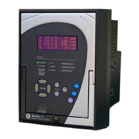
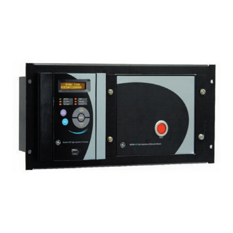
GE MDP User manual

MDP
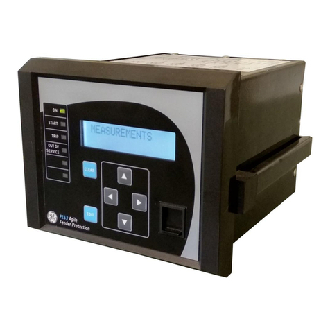
Digital Time Overcurrent Relay
Instruction Manual
MDP Revision: Rev. D
Manual P/N: GEK-100682D
Copyright © 2000 GE Power Management
GE Power Management
215 Anderson Avenue, Markham, Ontario
Canada L6E 1B3
Tel: (905) 294-6222 Fax: (905) 294-8512
Internet: http://www.GEindustrial.com/pm Manufactured under an
ISO9002 Registered system.
g
GE Power Management
Courtesy of NationalSwitchgear.com

These instructions do not purport to cover all details or variations in equipment
nor provide for every possible contin
g
ency to be met in connection with instal-
lation, operation, or maintenance. Should further information be desired or
should particular problems arise which are not covered sufficiently for the pur-
chaser’s purpose, the matter should be referred to the General Electric
Company.
To the extent required the products described herein meet applicable ANSI,
IEEE, and NEMA standards; but no such assurance is
g
iven with respect to
local codes and ordinances because they vary
g
reatly.
Courtesy of NationalSwitchgear.com

GE Power Management MDP Digital Time Overcurrent Relay
i
TABLE OF CONTENTS
1. INTRODUCTION 1.1 PRODUCT DESCRIPTION........................................................................ 1-1
1.2 ORDER CODES........................................................................................ 1-2
1.3 APPLICATION ........................................................................................... 1-4
1.4 INTERFERENCE SUPPRESSION GROUND CONNECTION.................. 1-5
1.5 TECHNICAL SPECIFICATIONS................................................................ 1-6
1.6 RANGES AND SETTINGS........................................................................ 1-7
2. OPERATING
PRINCIPLES 2.1 INPUTS...................................................................................................... 2-1
2.2 EXTERNAL INPUTS.................................................................................. 2-1
2.3 COMMUNICATIONS PORT ...................................................................... 2-1
2.4 MEASUREMENT....................................................................................... 2-3
2.5 INVERSE TIME UNIT................................................................................ 2-3
a 51 INVERSE (5 A RATED RELAYS)...................................................... 2-4
b BS142 INVERSE (1 A RATED RELAYS)............................................... 2-4
c 53 VERY INVERSE................................................................................ 2-4
d 77 EXTREMELY INVERSE.................................................................... 2-4
e 66 INVERSE LONG TIME...................................................................... 2-4
2.6 INSTANTANEOUS UNIT......................................................................... 2-10
2.7 CHANGING SETTINGS........................................................................... 2-10
2.8 SETTINGS............................................................................................... 2-11
a PICKUP TOC........................................................................................ 2-11
b PICKUP IOC......................................................................................... 2-11
c TIME DIAL............................................................................................ 2-11
d CURVE SELECTION............................................................................ 2-11
e IOC DELAY........................................................................................... 2-12
f COMMUNICATIONS ADDRESS.......................................................... 2-12
g
OUTPUT CONTACT CONFIGURATION ............................................. 2-12
2.9 DISPLAY AND RESET............................................................................ 2-13
2.10 SELF-TEST AND ERROR ROUTINES ................................................... 2-14
3. CONSTRUCTION 3.1 DESCRIPTION .......................................................................................... 3-1
3.2 DISPLAYS ................................................................................................. 3-3
3.3 RECEIVING, HANDLING, AND STORAGE .............................................. 3-3
4. INSTALLATION AND
MAINTENANCE 4.1 INSTALLATION ......................................................................................... 4-1
4.2 PERIODIC CHECKS AND ROUTINE MAINTENANCE.............................4-5
5. PERIODIC &
ACCEPTANCE TESTS 5.1 DESCRIPTION .......................................................................................... 5-1
5.2 VISUAL INSPECTION............................................................................... 5-1
5.3 INVERSE TIME UNIT................................................................................ 5-1
a PHASE PICKUP CALIBRATION VERIFICATION.................................. 5-1
b VERIFICATION OF OPERATING TIME................................................. 5-2
c VERIFICATION OF TIME DIAL.............................................................. 5-2
5.4 INSTANTANEOUS UNIT........................................................................... 5-3
a VERIFICATION OF PICKUP.................................................................. 5-3
b VERIFICATION OF OPERATING TIME................................................. 5-3
5.5 GROUND UNIT.......................................................................................... 5-3
Courtesy of NationalSwitchgear.com

ii
MDP Digital Time Overcurrent Relay GE Power Management
TABLE OF CONTENTS
6. MDP-LINK SOFTWARE 6.1 OVERVIEW................................................................................................ 6-1
6.2 SYSTEM REQUIREMENTS ...................................................................... 6-1
a HARDWARE........................................................................................... 6-1
b SOFTWARE ........................................................................................... 6-1
6.3 GENERAL OPERATION............................................................................ 6-3
a MOUSE/KEYBOARD USAGE................................................................ 6-3
b MAIN HORIZONTAL MENU BAR...........................................................6-3
c PULL-DOWN MENUS ............................................................................ 6-3
d DIALOG BOXES.....................................................................................6-3
e LIST BOXES........................................................................................... 6-4
f ENTERING TEXT AND NUMBERS .......................................................6-4
6.4 MAIN MENU .............................................................................................. 6-5
a MAIN MENU ........................................................................................... 6-5
6.5 RELAY FUNCTIONS .................................................................................6-5
a LOGIN..................................................................................................... 6-5
b LOGOUT................................................................................................. 6-5
c HANG UP PHONE.................................................................................. 6-6
d REQUEST RELAY DATA....................................................................... 6-6
e REQUEST FAULT DATA ....................................................................... 6-6
f RESET FAULT DATA............................................................................. 6-6
g
BREAKER STATUS ............................................................................... 6-7
h TRIP BREAKER .....................................................................................6-7
i CLOSE BREAKER .................................................................................6-7
6.6 LOCAL FUNCTIONS .................................................................................6-8
6.7 SETUP....................................................................................................... 6-8
a COMMUNICATION PORT NUMBER..................................................... 6-8
b DIAL TYPE ............................................................................................. 6-8
c MODEM CONNECTION TIME ............................................................... 6-8
d RELAY PARAMETERS .......................................................................... 6-9
e ADD RELAY TO LIST.............................................................................6-9
f DELETE RELAY FROM LIST................................................................. 6-9
g
DISPLAY MODE...................................................................................6-10
h MEMORY AVAILABLE......................................................................... 6-10
6.8 HELP........................................................................................................6-10
6.9 EXITING MDP-LINK ................................................................................ 6-10
7. MODBUS PROTOCOL 7.1 DESCRIPTION .......................................................................................... 7-1
7.2 OVERVIEW................................................................................................ 7-1
7.3 MODBUS COMMANDS............................................................................. 7-1
a READ HOLDING REGISTERS, FUNCTION CODE 03..........................7-1
b READ INPUT REGISTERS, FUNCTION CODE 04 ............................... 7-2
c FORCE SINGLE COIL: FUNCTION CODE 05....................................... 7-2
7.4 MODBUS MEMORY MAP ......................................................................... 7-3
7.5 COIL COMMANDS .................................................................................... 7-6
7.6 EVENT HANDLING ...................................................................................7-6
A. MDP FAQ A.1 FREQUENTLY ASKED QUESTIONS .......................................................A-1
B. CHANGE NOTES B.1 REVISION HISTORY.................................................................................B-1
B.2 ADDITIONS TO MDP MANUAL ................................................................B-1
B.3 CHANGES TO MDP MANUAL ..................................................................B-2
Courtesy of NationalSwitchgear.com

GE Power Management MDP Digital Time Overcurrent Relay 1-
1
GEK-100682D 1 INTRODUCTION
1
1 INTRODUCTION 1.1 PRODUCT DESCRIPTION
The MDP Digital Time Overcurrent Relay is a digital, microprocessor based, nondirectional overcurrent relay
that protects against phase-to-phase and phase-to-ground faults. The MDP™ performs the following functions:
• Inverse overcurrent, including four characteristic curves and four values of definite time protection, as well
as instantaneous overcurrent protection with programmable delay
• Phase and ground current measurement
• Phase and ground current metering
• Operating time and fault current of the last trip
• Breaker status
• Breaker operation (RS232 and RS485 versions only)
The MDP™ series relays include four measuring units, one for each of the three phase currents and an addi-
tional one for ground or residual current. Each of the four measuring units includes a time and an instanta-
neous overcurrent unit. The phase settings are combined so that all phase units are set the same.
The pickup value for the instantaneous unit can be adjusted between 1 and 31 times the value selected for the
inverse time unit.
The instantaneous unit can be disabled by adjusting the setting to zero times the inverse value. The MDP relay
has two trip output relays that can be selected to indicate whether a trip has been produced by
• an instantaneous unit or an inverse unit, or
• by phase or ground.
This selection is made by means of a switch behind the right lower side of the nameplate. An alarm output is
provided to signal a critical alarm (such as power supply failure or self check failure). An output contact is pro-
vided to close the breaker from a command issued via the communications channel.
A single-line diagram illustrating the functionality of the MDP relay is shown on the following page. A typical
wiring diagram is shown in Figure 1–2: TYPICAL WIRING DIAGRAM on page 1–3.
Table 1–1: CURRENT RANGES
NOMINAL
CURRENT (In) INVERSE TIME UNIT (Is) INSTANTANEOUS
UNIT
PHASE GROUND
5 A 1.5 to 13.25 A
1.5 to 13.125 A
1 to 31 ×Is
(all relays)
0.5 to 4.375 A
0.1 to 0.875 A
0.5 to 4.375 A 0.5 to 4.735 A
1 A 0.3 to 2.625 A
0.3 to 2.625 A
0.1 to 0.875 A
0.05 to 0.4375 A
(½ A CT)
Courtesy of NationalSwitchgear.com

1-
2
MDP Digital Time Overcurrent Relay GE Power Management
1 INTRODUCTION GEK-100682D
1
Figure 1–1: SINGLE-LINE DIAGRAM
1.2 ORDER CODES
MDP SSSSS
0No communications or control inputs
(Block Ground, Block Instantaneous, Breaker Status)
1 Control Inputs and communications upgrade socket
2 CommNet
3 Modbus RTU
4RS232
5RS485
15 A nominal, 0.5 to 4.375 A ground, 1.5 to 13.125 A phase
25 A nominal, 1.5 to 13.125 A ground, 1.5 to 13.125 A phase
35 A nominal, 0.1 to 0.875 A ground, 1.5 to 13.125 A phase
41 A nominal, 0.1 to 0.875 A ground, 0.3 to 2.625 A phase
51 A nominal, 0.3 to 2.625 A ground, 0.3 to 2.625 A phase
61 A nominal, 0.05 to 0.4375 A ground, 0.3 to 2.625 A phase
75 A nominal, 0.5 to 4.375 A ground and phase
1 24 to 48 V DC
2 48 to 125 V DC, 35 to 120 V AC
3 110 to 250 V DC, 85 to 240 V AC
00000 Reserved
DRevision Level
707750A1.CDR
BUS 1
TRANSFORMER 1
FEEDER
NO. 1
FEEDER
NO. 3
FEEDER
NO. 2
50/51
50/51
50/51 50/51
Courtesy of NationalSwitchgear.com

GE Power Management MDP Digital Time Overcurrent Relay 1-
3
GEK-100682D 1 INTRODUCTION
1
Figure 1–2: TYPICAL WIRING DIAGRAM
SWITCHGEAR
GROUND BUS
1
110
1A
1A
1A
1A
1B
1B
1B
1B
1C
1C
1C
1C
1G
1G
1G
1G
2
220
POWER
SUPPLY
3
3
4
4
5
5
6
6
7
7
8
8
13
12
11
T
T
52a 52a
TRIP
COIL
ALTERNATIVE CT WIRING
FOR RESIDUAL GROUND SENSING
ZERO SEQUENCE GROUND
SENSING CONNECTION
A
B
C
CONTROL
POWER
CIRCUIT BREAKER
CURRENT INPUTS
CURRENT INPUTS
SHIELDED
TWISTED PAIR
RS232
707754A3.CDR
14
15
16
17
18
GE Power Management
CP7
CP4
CP8
CP5
CP6 TX
RX
COM
CP1
CP3
CP2
9
19
Courtesy of NationalSwitchgear.com
1-
4
MDP Digital Time Overcurrent Relay GE Power Management
1 INTRODUCTION GEK-100682D
11.3 APPLICATION
Time-overcurrent relays are used for the protection of feeders, transmission lines, alternating-current machines
and transformers, and numerous other applications where accurate measurement of current and timing is nec-
essary. To ensure proper coordination with a minimum of circuit isolation, the operating time of associated pro-
tective devices should be considered when selecting a time-current characteristic for a particular application.
Four basic time-current characteristics are available for the MDP relay:
1. INVERSE / BS142 INVERSE: The inverse time current characteristic curves are shown in the following
diagrams:
• Figure 2–4: INVERSE TIME CURVE on page 2–5.
• Figure 2–5: LONG INVERSE TIME CURVE on page 2–6.
• Figure 2–8: BS142 INVERSE TIME CURVE (1 A MODELS ONLY) on page 2–9.
The BS142 inverse curve applies to the 1 A model relays only. These relays are generally applied where
the short circuit current magnitude is dependent largely upon the system generating capacity at the time of
the fault.
2. VERY INVERSE: The very inverse time-current characteristic shown in Figure 2–6: VERY INVERSE TIME
CURVE on page 2–7 is generally applied where the magnitude of short circuit current flowing through any
given relay is more dependent upon the location of the fault relative to the relay than on the system gener-
ation setup at the time of the fault.
3. EXTREMELY INVERSE: The extremely inverse time-current characteristic shown in Figure 2–7:
EXTREMELY INVERSE TIME CURVE on page 2–8 is preferred for applications where sufficient time
delay must be provided to allow a re-energized circuit to pick up an accumulated cold load without unnec-
essary tripping on inrush currents. Distribution feeder circuits are a good example of such applications, and
the extremely-inverse characteristic is best suited to such applications because it more nearly approxi-
mates typical power fuse and fuse cutout characteristics.
The general practice for grounded distribution system protection is to use three-phase overcurrent functions for
protection against interphase faults and a ground/residual overcurrent function for single phase-to-ground
faults. The use of a separate ground-overcurrent function is advantageous because it can generally be
adjusted to provide faster and more sensitive protection for single phase-to-ground faults than the phase over-
current functions. Typical connections for such an application are shown in Figure 4–2: TYPICAL EXTERNAL
CONNECTIONS, GROUND CURRENTS and Figure 4–3: TYPICAL EXTERNAL CONNECTIONS, RESIDUAL
CURRENTS on pages 4–2 and 4–3.
The pickup setting of the MDP time unit should be chosen so that it operates for all short circuits in the pro-
tected zone and, when possible, also provides backup protection for short circuits in the immediately adjacent
system element. The time unit pickup should be set low enough to ensure that the minimum fault current is at
least 1.5 times the setting.
The time delay adjustment of the time unit should be chosen to assure selectivity with the protection on the
adjacent system elements. This adjustment should be made for the condition that yields maximum fault current
at the relay location. The time delay is determined by the adjacent relay operating time for this condition, plus a
coordinating time allowance that includes the adjacent circuit breaker maximum operating time and a safety
factor to accommodate any uncertainties. Since the MDP time unit has insignificant overtravel, the only relay
variation that needs consideration in the safety factor is the tolerance on the time curves. A 0.17 second safety
factor is generally used if the relay time is determined by selecting a time dial setting from the time curves. This
safety factor can be reduced to 0.07 second if the time unit is instead set to the desired time by accurate tests.
Courtesy of NationalSwitchgear.com
GE Power Management MDP Digital Time Overcurrent Relay 1-
5
GEK-100682D 1 INTRODUCTION
1
The instantaneous overcurrent unit can be applied in many instances to reduce the fault clearing time for high
fault currents. This unit is normally set to pick up only on internal faults in the protected zone. Significant tran-
sient overreach can be experienced under certain conditions, and this must be taken into account by selecting
a pickup setting that is higher than that which would be dictated by the maximum steady state external fault
current.
IMPORTANT: If one unit (instantaneous or inverse) operates, the other unit (inverse or instan-
taneous)
will also
operate. The MDP fault report will record the first fault that occurred. When
the fault is cleared, the fault LEDs will display Phase-Phase, Phase-Ground, Instantaneous,
and Inverse Time faults. See display section on how to interpret the display for various fault
conditions. The MDP generates a new fault report when the fault current drops below the pick-
up value and a new fault occurs.
Contact converter input CC1 and the output select switch of the MDP allow a zone selective interlocking of the
MDP relays. This scheme provides instantaneous operation (with a minimum time delay) of the upstream relay
for faults between the upstream and downstream relays. Refer to Figure 4–4: TYPICAL EXTERNAL CON-
NECTIONS, ZONE SELECTIVE INTERLOCK on page 4–4 for a typical scheme and settings considerations.
Note that all the feeders must be radial, with no (or very weak) source.
1.4 INTERFERENCE SUPPRESSION GROUND CONNECTION
The MDP relay contains high frequency interference protection consisting of a series of capacitors connected
between the input terminals and the case.
The case stud of the relay should be connected to ground, so these interference suppression circuits can per-
form their protective function. This connection should be as short as possible, to assure maximum protection.
Braided #12 AWG conductors are recommended.
NOTE
Courtesy of NationalSwitchgear.com
1-
6
MDP Digital Time Overcurrent Relay GE Power Management
1 INTRODUCTION GEK-100682D
11.5 TECHNICAL SPECIFICATIONS
ELECTRICAL RATINGS
Nominal frequency: 25/50/60 Hz
Nominal current: 1 or 5 A
Auxiliary Power Supply: 24 to 48 V DC, 48 to 125 V DC / 38.5 to 150 V AC, 110 to 250 V DC, 85 to 240 V AC
BURDEN RATINGS
OVERCURRENT RATINGS
Continuous: 2 x In
Three Second: 50 x In
One Second: 100 x In
CT RATINGS
1 A 34500
5 A 87500
1 A special 13600 (models MDPx6 have a sensitive ground CT)
ENVIRONMENTAL RATINGS
Temperature: Operating: –20°C to +65°C (–40°C available upon request)
Storage: –40°C to +65°C
Relative Humidity: Up to 95% without condensing
ACCURACY
Operating Value: 5%
Operating Time: 5% or 0.025 seconds, whichever is greater
REPEATABILITY
Operating Value: 1%
Operating Time: 2% or 0.025 seconds, whichever is greater
DIGITAL INPUT
Voltage Range: 38.5 to 250 V AC, 24 to 250 V DC
Frequency Range: 40 to 70 Hz
OUTPUT AND TRIP CONTACTS
Closing: Contact will close and conduct up to a maximum of 30 A for tripping duty at control voltages up to
300 V DC. The output contact is also rated for Capacitive trip devices.
Interrupting: 50 W resistive with a maximum of 2 A and 300 V DC
Continuous: 5 A, with 300 V DC maximum
Frequency range: 25 to 70 Hz (note: the MDP responds to RMS values of harmonics to 600 Hz)
GROUND
CT MDP
MODEL1
1. Refers to the MDP*
X
model, see Section 1.2: ORDER CODES on page 1–2
PHASE
INPUT BURDEN POWER SUPPLY
AC/DC
50 Hz AC 60 Hz AC
1 A
6 0.05 to 0.4375 A
<3 W at all voltages,
quiescent
<4.5 W at maximum
voltages
4 0.1 to 0.875 A 0.09 Ω∠2.4° 0.09 Ω∠2.8°
5 0.3 to 2.625 A
5 A
3 0.1 to 0.875 A
1, 7 0.5 to 4.375 0.01 Ω ∠9.7° 0.01 Ω ∠11.5°
2 1.5 to 13.125 A
Courtesy of NationalSwitchgear.com
GE Power Management MDP Digital Time Overcurrent Relay 1-
7
GEK-100682D 1 INTRODUCTION
1
1.6 RANGES AND SETTINGS
The following indicates the ranges of standard models.
NOMINAL CURRENT
5 A Phase Unit Models (models 1 to 3):
Phase Unit: 1.5 to 13.125 A in cumulative increments of 0.375, 0.750, 1.50, 3.0, and 6.0 A
Ground Unit model 1: 0.5 to 4.375 A in cumulative increments of 0.125, 0.250,0.50,1.0, and 2.0 A
Ground Unit model 2: 1.5 to 13.125 Amps in cumulative increments of 0.375, 0.750, 1.50, 3.0, and 6.0 A
Ground Unit model 3: 0.1 to 0.875 Amp in cumulative increments of 0.025, 0.050, 0.10, 0.2, and 0.4 A
5 A Phase Unit Model (model 7):
Phase Unit: 0.5 to 4.375 A in cumulative increments of 0.125, 0.25, 0.50, 1.0, and 2.0 A
Ground Unit: 0.5 to 4.375 A in cumulative increments of 0.125, 0.250, 0.50, 1.0, and 2.0 A
1 A Phase Unit (models 4 to 6):
Phase Unit: 0.3 to 2.625 A in cumulative increments of 0.075, 0.150, 0.30, 0.60, and 1.20 A
Ground Unit model 4: 0.1 to 0.875 A in cumulative increments of 0.025, 0.050, 0.10, 0.2, and 0.4 A
Ground Unit model 5: 0.3 to 2.625 A in cumulative increments of 0.075, 0.150, 0.30, 0.6, and 1.2 A
Ground Unit model 6: 0.05 to 0.4375 A in cumulative increments of 0.0125, 0.0250,0.050,0.1, and 0.2 A
TIME DELAY (TOC)
Independent for phase and ground.
Depends on the curve selected. Five Inverse Time curves are available (see Section 2.5: INVERSE TIME UNIT on page 2–
3), as well as four definite times (maximum time 2, 4, 6, and 8 seconds), all in the same relay.
INSTANTANEOUS UNIT PICKUP
Independent for phase and ground.
1 to 31 times the pickup of the TOC setting.
A setting of zero (0) disables instantaneous unit. (X) no multiples selected.
INSTANTANEOUS UNIT TIME DELAY
Independent for phase and ground.
0 to 1.55 seconds in 50 millisecond steps.
PHASE OPERATING CURVES CURVE SELECTION
Available Curves: Inverse/BS142* (for 1 A models), Long Time Inverse, Very Inverse, Extremely Inverse, Four families
of definite time characteristics with maximum values of 2, 4, 6, and 8 seconds
Between each family of curves, a specific curve can be selected between 0.5 and 10 in cumulative steps of 0.5, 1, 2, 2 and
4 for 5 a relays. The 1 A model range is from 0.05 to 1.0 in cumulative steps of 0.05, 0.1, 0.2, 0.2, and 0.4.
GROUND OPERATING CURVES CURVE SELECTION
Available Curves: Inverse/BS142* (for 1 A models), Long Time Inverse, Very Inverse, Extremely Inverse, Four families
of definite time characteristics with maximum values of 2, 4, 6, and 8 seconds
Between each family of curves, a specific curve can be selected between 0.5 and 10 in cumulative steps of 0.5, 1, 2, 2, and
4 for 5 amp relays. A 1 amp model's range is from 0.05 to 1.0 in cumulative steps of 0.05, 0.1, 0.2, 0.2, and 0.4.
BS142 is the INVERSE curve of the 1 A model.
COMMUNICATIONS ADDRESS
Range: 002 to 998.
A setting of 000 indicates no communications and sets the default display to phase A Current.
For RS232 and RS485 all relays will respond to address 001.
All values are adjusted with DIP switches located at the front of the relay, except the communications
address, which is located on the rear of the cradle.
NOTE
NOTE
NOTE
Courtesy of NationalSwitchgear.com
GE Power Management MDP Digital Time Overcurrent Relay 2
-
1
GEK-100682D 2 OPERATING PRINCIPLES
2
2 OPERATING PRINCIPLES 2.1 INPUTS
The secondary current from the protected line current transformers is connected to the relay and immediately
reduced via the internal current transformers. The MDP CT secondaries are connected across input resistors,
yielding a voltage proportional to the relay input current. This voltage is rectified and filtered before being
applied to the multiplexer and analog-to-digital converter, which are internal to the microprocessor.
2.2 EXTERNAL INPUTS
Three external inputs (CP4, CP6, and CP7) are provided.
• CP4 – Block IOC Trip: when energized, blocks tripping by the ground units.
• CP6 – Block Ground Trip: blocks the phase and ground instantaneous trip elements when it is energized.
• CP7 – Breaker Status Input: when energized, indicates that the Breaker Status is "closed".
Since diode bridges are provided on all inputs, they can all be actuated by either switched-to-positive or
switched-to-negative, depending on the polarity connected to the stud. These inputs can be energized by
either AC or DC.
The Breaker Status and Block Ground inputs, CP7 and CP6 respectively, must be switched by the
same polarity, since they share a common ground (CP8).
2.3 COMMUNICATIONS PORT
The MDP relay has a communications feature that permits easy installation of various communications inter-
face modules. The procedure for installation/replacement of a communications upgrade card is provided
below:
1. To install or replace a communications upgrade card, begin by removing the relay from the case.
2. Before continuing, connect an approved wrist grounding strap to ground. This discharges any static elec-
tricity in your body that could damage the electronics of the MDP relay. A wrist strap is provided with the
communications card kit. The wrist strap must provide a "safe" high resistance to ground.
3. Remove four screws attaching the nameplate settings board and the NOMEX insulation paper to the relay
cradle (see the cover photograph). Note that there are four metal spacers between the nameplate and the
settings board. Be careful not to lose them or let them fall into the relay assembly. Carefully place the set-
tings board on top of the cradle to expose the communication card SIMM socket located on the lowest
board (digital input/communications board).
4. To expose the SIMM socket located on the lowest board, carefully push down on the board to disengage
the board spacers. Do not try to remove the board from the cradle
5. This step is for replacement only – skip to step 6 if you are installing the card for the first time. If you are
replacing an existing SIMM card, the old one must be removed! Start by simultaneously pushing the
catches on either side of the SIMM board outwards while lifting the board to a 45° angle. This will release
the board.
NOTE
Courtesy of NationalSwitchgear.com
2
-
2
MDP Digital Time Overcurrent Relay GE Power Management
2 OPERATING PRINCIPLES GEK-100682D
2
6. Remove the communications card from its protective packaging. Insert the card into the SIMM socket at a
45° angle to the socket with the integrated circuits facing up. Push the card down until it snaps into the
socket and the latches on either side of the board catch above the new board
Figure 2–1: DIGITAL INPUT/COMMUNICATIONS BOARD
7. Reassemble the MDP relay by engaging the board spacers of the lowest board (digital input/communica-
tions board) into the processor board above it. Align the NOMEX shield on the solder side of the settings
board. Take one screw and spacer at a time and push the screw through the nameplate, spacer, settings
board and NOMEX. The NOMEX protects the ribbon cable from the leads on the settings board.
Figure 2–2: COMMUNICATIONS CARD INSTALLED
Without Communications Upgrade Card Communications Upgrade Card Installed
Before DI/Comm Board is Raised Back into Position With DI/Comm Board in Position
Courtesy of NationalSwitchgear.com

GE Power Management MDP Digital Time Overcurrent Relay 2
-
3
GEK-100682D 2 OPERATING PRINCIPLES
2
8. Tighten the screw just enough to hold the assembly in place until all four screws are aligned. When all the
screws are aligned, tighten them with gentle pressure so that the board is mounted evenly.
9. SET THE COMMUNICATIONS ADDRESS before restoring the cradle to the case.
Figure 2–3: REAR VIEW SHOWING COMMUNICATION ADDRESS SWITCHES
2.4 MEASUREMENT
A timer internal to the microprocessor generates an interrupt every millisecond. Phase and ground measure-
ments are made at each of these interrupts. These measurements are grouped, separately for each phase and
ground, in groups of ten, and the average of the maximum value of these groups is taken.
This average is converted to a multiple of pickup TOC, the format used by the relay. This value is displayed in
5 second intervals.
2.5 INVERSE TIME UNIT
The multiple of pickup TOC measurement obtained is compared, independently for each phase and ground,
with a value, the pickup setting, that corresponds to one times (1×) pickup TOC. If the measurement exceeds
the fixed setting, a Pickup LED lights on the front of the relay.
The minimum current necessary to operate the Inverse Time measuring elements is never less than the set
value (
I
s
), nor greater than 10% more than (110% of) the set value.
The dropout to pickup ratio is not less than 95%, based on the actual operating value.
The MDP relay incorporates five inverse time curves and four definite times. The curve within a family is
selected by the time dial. The characteristic curves for the MDP relay correspond approximately as follows.
1.0
I
s
I
min
1.1
I
s
<<
Courtesy of NationalSwitchgear.com
2
-
4
MDP Digital Time Overcurrent Relay GE Power Management
2 OPERATING PRINCIPLES GEK-100682D
2
a) 51 INVERSE (5 A RATED RELAYS)
For 1.1 to 4 times the pickup TOC:
For 4 to 31 times the pickup TOC:
See Figure 2–4: INVERSE TIME CURVE on page 2–5.
b) BS142 INVERSE (1 A RATED RELAYS)
For 1 to 31 times the pickup TOC:
See Figure 2–8: BS142 INVERSE TIME CURVE (1 A MODELS ONLY) on page 2–9.
c) 53 VERY INVERSE
For 1.1 to 4 times the pickup TOC:
For 4 to 31 times the pickup TOC:
See Figure 2–6: VERY INVERSE TIME CURVE on page 2–7
d) 77 EXTREMELY INVERSE
For 1.1 to 20 times the pickup TOC:
See Figure 2–7: EXTREMELY INVERSE TIME CURVE on page 2–8.
e) 66 INVERSE LONG TIME
For 1.1 to 3 times the pickup TOC:
For 3 to 5 times the pickup TOC:
For 5 to 20 times the pickup TOC:
For 20 to 31 times the pickup TOC:
See Figure 2–5: LONG INVERSE TIME CURVE on page 2–6.
For all the above equations:
T
= time in seconds
P
= multiple of pickup TOC
Time Dial = for 5 A rated unit
= Time Dial Setting for 1 A rated unit
T
0.0059
P
0.001 1–
------------------------ 0.419+
Time Dial
×0.018+=
T
0.0069
P
0.001 1–
------------------------ 0.252–
Time Dial
×0.018+=
T
0.14
P
0.02 1–
----------------------
Time Dial
×0.018+=
T
52.954
P
2.11 1–
----------------------0.923+
Time Dial
×0.018+=
T
28.447
P
1.702 1–
------------------------ 1.007+
Time Dial
×0.018+=
T
58.132
P
2.135 1–
------------------------ 0.166+
Time Dial
×0.020+=
T
0.0006
P
0.00001 1–
----------------------------- 5.644+
Time Dial
×
=
T
0.746
P
0.01 1–
----------------------5.630–
Time Dial
×
=
T
0.00085
P
0.00001 1–
----------------------------- 12.530–
Time Dial
×
=
T
250 4.5
P
×
–10
----------------------------------
Time Dial
×
=
Time Dial Setting
10
---------------------------------------------
Courtesy of NationalSwitchgear.com
Other manuals for MDP
1
Table of contents
Other GE Relay manuals