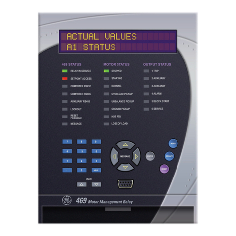
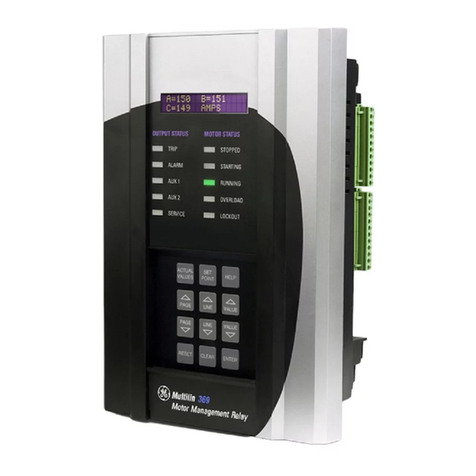
GE 269Plus User manual

269Plus
Motor Management Relay
Instruction Manual
Firmware Revision: 269P.E6.0.4
Manual P/N: 1601-0013-E2 (GEK-106287A)
Copyright © 2002 GE Power Management
GE Power Management
215 Anderson Avenue, Markham, Ontario
Canada L6E 1B3
Tel: (905) 294-6222 Fax: (905) 294-8512
Internet:
http://www.GEindustrial.com/pm
Manufactured under an
ISO9001 Registered system.
g
GE Power Managemen
t


These instructions do not purport to cover all details or variations in equipment nor provide
for every possible contingency to be met in connection with installation, operation, or main-
tenance. Should further information be desired or should particular problems arise which are
not covered sufficiently for the purchaser’s purpose, the matter should be referred to the
General Electric Company.
To the extent required the products described herein meet applicable ANSI, IEEE, and
NEMA standards; but no such assurance is given with respect to local codes and ordi-
nances because they vary greatly.


GE Power Management 269Plus Motor Management Relay
i
TABLE OF CONTENTS
1. INTRODUCTION 1.1 MOTOR PROTECTION REQUIREMENTS............................................... 1-1
1.2 FEATURES................................................................................................ 1-1
1.3 TYPICAL APPLICATIONS......................................................................... 1-4
1.4 ORDER CODE / INFORMATION .............................................................. 1-5
1.5 TECHNICAL SPECIFICATIONS................................................................ 1-6
1.6 MPM OPTION SPECIFICATIONS............................................................. 1-9
2. INSTALLATION 2.1 PHYSICAL DIMENSIONS ......................................................................... 2-1
2.2 MOUNTING ............................................................................................... 2-6
2.3 EXTERNAL CONNECTIONS .................................................................... 2-7
2.4 CONTROL POWER................................................................................. 2-12
2.5 PHASE CT INPUTS................................................................................. 2-14
2.6 GROUND CT INPUT ............................................................................... 2-15
2.7 TRIP RELAY CONTACTS.......................................................................2-17
2.8 ALARM RELAY CONTACTS................................................................... 2-18
2.9 AUXILIARY RELAY #1 CONTACTS........................................................ 2-18
2.10 AUXILIARY RELAY #2 CONTACTS........................................................ 2-19
2.11 RTD SENSOR CONNECTIONS.............................................................. 2-19
2.12 EMERGENCY RESTART TERMINALS .................................................. 2-20
2.13 EXTERNAL RESET TERMINALS ........................................................... 2-21
2.14 ANALOG OUTPUT TERMINALS (NON-ISOLATED).............................. 2-21
2.15 DIFFERENTIAL RELAY TERMINALS..................................................... 2-21
2.16 SPEED SWITCH TERMINALS................................................................ 2-22
2.17 PROGRAMMING ACCESS TERMINALS................................................ 2-22
2.18 RS485 SERIAL COMMUNICATIONS TERMINALS................................2-22
2.19 DISPLAY ADJUSTMENT......................................................................... 2-24
2.20 FRONT PANEL FACEPLATE.................................................................. 2-24
2.21 SPARE INPUT TERMINALS ................................................................... 2-24
2.22 DRAWOUT RELAY OPTION................................................................... 2-25
2.23 METER OPTION INSTALLATION........................................................... 2-29
a MPM EXTERNAL CONNECTIONS...................................................... 2-29
b MPM WIRING....................................................................................... 2-29
c CONTROL POWER (5/6/7/8)............................................................... 2-29
d VT INPUTS (1-4) .................................................................................. 2-30
e CT INPUTS (9-20)................................................................................ 2-30
f SERIAL COMMUNICATIONS PORT (COM1 - 46,47,48) .................... 2-31
g MPM ANALOG OUTPUT...................................................................... 2-31
3. SETUP AND USE 3.1 FRONT PANEL.......................................................................................... 3-1
3.2 CONTROLS AND INDICATORS............................................................... 3-2
3.3 RELAY DISPLAY MODES......................................................................... 3-6
3.4 ACTUAL VALUES MODE.......................................................................... 3-7
a STARTS/HOUR TIMER........................................................................ 3-15
b TIME BETWEEN STARTS TIMER....................................................... 3-16
c CAUSE OF LAST TRIP........................................................................ 3-16
d CAUSE OF LAST EVENT ....................................................................3-16
3.5 SETPOINTS MODE................................................................................. 3-17
3.6 HELP MODE............................................................................................ 3-43
3.7 TRIP/ALARM MODE................................................................................ 3-43
3.8 PHASE CT & MOTOR FULL LOAD CURRENT SETPOINTS................. 3-47
3.9 ACCELERATION TIME SETPOINT ........................................................ 3-47
3.10 INHIBITS.................................................................................................. 3-48
3.11 UNBALANCE SETPOINTS...................................................................... 3-49
3.12 GROUND FAULT (EARTH LEAKAGE) SETPOINTS.............................. 3-50

ii
269Plus Motor Management Relay GE Power Management
TABLE OF CONTENTS
3.13 CONTACTOR/BREAKER WIRING..........................................................3-51
3.14 UNDERCURRENT SETPOINTS ............................................................. 3-52
3.15 RAPID TRIP / MECHANICAL JAM SETPOINTS.....................................3-52
3.16 SHORT CIRCUIT SETPOINTS ............................................................... 3-52
3.17 IMMEDIATE OVERLOAD ALARM SETPOINT........................................ 3-53
3.18 STATOR RTD SETPOINTS..................................................................... 3-53
3.19 OTHER RTD SETPOINTS....................................................................... 3-54
3.20 OVERLOAD CURVE SETPOINTS..........................................................3-55
3.21 THERMAL CAPACITY ALARM ............................................................... 3-59
3.22 THERMAL MEMORY...............................................................................3-59
a U/B INPUT TO THERMAL MEMORY................................................... 3-60
b RTD INPUT TO THERMAL MEMORY ................................................. 3-61
c LEARNED COOLING TIMES ............................................................... 3-62
d START INHIBIT .................................................................................... 3-62
3.23 EMERGENCY RESTART........................................................................ 3-63
3.24 RESETTING THE RELAY .......................................................................3-64
a SINGLE SHOT RESTART.................................................................... 3-64
b SPECIAL EXTERNAL RESET..............................................................3-64
3.25 RELAY SELF-TEST.................................................................................3-65
3.26 STATISTICAL DATA FEATURES ........................................................... 3-65
3.27 FACTORY SETPOINTS .......................................................................... 3-65
3.28 METER OPTION...................................................................................... 3-66
a THE PHENOMENON ........................................................................... 3-68
b RECOMMENDATIONS ........................................................................ 3-68
3.29 PRESET CONFIGURATIONS / FUNCTIONS.........................................3-69
4. COMMUNICATIONS 4.1 INTRODUCTION ....................................................................................... 4-1
4.2 MODES OF OPERATION.......................................................................... 4-1
4.3 PHYSICAL LAYER .................................................................................... 4-1
4.4 PACKET FORMAT .................................................................................... 4-3
4.5 THE HANDSHAKE .................................................................................... 4-4
4.6 SUPPORTED FUNCTIONS....................................................................... 4-5
a FUNCTION 03h: READ SETPOINTS (HOLDING REGISTERS) ...........4-5
b FUNCTION 04H: READ ACTUAL VALUES (INPUT REGISTERS) ....... 4-6
c FUNCTION 16 (10H): WRITE SETPOINT VALUES .............................. 4-6
4.7 EXCEPTION OR ERROR REPLIES..........................................................4-7
4.8 ERROR CHECKING CODE....................................................................... 4-8
a DESCRIPTION ....................................................................................... 4-8
b CRC-16 ALGORITHM ............................................................................ 4-8
c SAMPLE PACKET WITH CRC-16.......................................................... 4-9
4.9 MEMORY MAP.......................................................................................... 4-9
4.10 FORMAT CODES.................................................................................... 4-24
5. RELAY TESTING 5.1 PRIMARY INJECTION TESTING..............................................................5-1
5.2 SECONDARY INJECTION TESTING........................................................ 5-1
5.3 PHASE CURRENT INPUT FUNCTIONS .................................................. 5-1
5.4 GROUND FAULT CURRENT FUNCTIONS.............................................. 5-4
5.5 RTD MEASUREMENT TESTS.................................................................. 5-4
5.6 POWER FAILURE TESTING..................................................................... 5-5
5.7 ANALOG CURRENT OUTPUT.................................................................. 5-5
5.8 ROUTINE MAINTENANCE VERIFICATION .............................................5-5
5.9 DIELECTRIC STRENGTH (HI-POT) TEST............................................... 5-6

GE Power Management 269Plus Motor Management Relay
iii
TABLE OF CONTENTS
6. THEORY OF OPERATION 6.1 HARDWARE.............................................................................................. 6-1
6.2 FIRMWARE ............................................................................................... 6-3
7. APPLICATION
EXAMPLES 7.1 RELAY POWERED FROM ONE OF MOTOR PHASE INPUTS ...............7-1
7.2 CONTROL POWER LOSS DUE TO SHORT CIRCUIT/GROUND FAULT7-1
7.3 USING FLC THERMAL CAPACITY REDUCTION SETPOINT................. 7-1
8. 269PC SOFTWARE 8.1 OVERVIEW................................................................................................ 8-1
8.2 HARDWARE & SOFTWARE REQUIREMENTS ....................................... 8-1
8.3 TOOLBAR SUMMARY .............................................................................. 8-1
8.4 MENU SUMMARY..................................................................................... 8-2
8.5 HARDWARE CONFIGURATION............................................................... 8-3
8.6 269PC INSTALLATION ............................................................................. 8-4
8.7 STARTUP AND COMMUNICATIONS CONFIGURATION........................ 8-5
8.8 ENTERING SETPONITS........................................................................... 8-6
8.9 SAVING SETPOINTS TO A FILE..............................................................8-8
8.10 LOADING SETPONTS FROM A FILE....................................................... 8-9
8.11 VIEWING ACTUAL VALUES................................................................... 8-10
8.12 TRENDING.............................................................................................. 8-12
8.13 USING THE TROUBLESHOOTING FEATURE ...................................... 8-13
9. COMMISSIONING 9.1 269PLUS COMMISSIONING SUMMARY ................................................. 9-1
9.2 REVISION HISTORY................................................................................. 9-5
A. 269 PLUS UNBALANCE
EXAMPLE A.1 DESCRIPTION ..........................................................................................A-1
A.2 EXAMPLE..................................................................................................A-1
B. THERMAL MODEL &
BIAS FEATURE B.1 THERMAL MODEL....................................................................................B-1
B.2 269 PLUS RTD BIAS FEATURE...............................................................B-2
C. RTD CIRCUITRY C.1 DESCRIPTION ..........................................................................................C-1
C.2 REDUCED WIRING RTDS........................................................................C-2
C.3 TWO-WIRE RTD LEAD COMPENSATION...............................................C-3
D. TWO PHASE CT
CONFIGURATION D.1 DESCRIPTION ..........................................................................................D-1

iv
269Plus Motor Management Relay GE Power Management
TABLE OF CONTENTS
E. ASYMMETRICAL
STARTING CURRENT E.1 DESCRIPTION ..........................................................................................E-1
F. DOs AND DON’Ts F.1 DESCRIPTION ..........................................................................................F-1
F.2 DOs............................................................................................................F-1
a 269PLUS GROUNDING ............................................................................F-1
b GROUNDING OF PHASE AND GROUND CTS........................................F-1
c RTDS.........................................................................................................F-1
d RS485 COMMUNICATIONS PORT ..........................................................F-2
F.3 DON’Ts ......................................................................................................F-3
G. GROUND FAULT &
SHORT CIRCUIT
INSTANTANEOUS
ELEMENTS
G.1 DESCRIPTION ......................................................................................... G-1
H. CURRENT
TRANSFORMERS H.1 269 PLUS CT WITHSTAND ......................................................................H-1
H.2 CT SIZE AND SATURATION ....................................................................H-1
I. FIGURES AND TABLES I.1 LIST OF FIGURES .....................................................................................I-1
I.2 LIST OF TABLES........................................................................................I-2
INDEX

GE Power Management 269Plus Motor Management Relay 1-
1
1 INTRODUCTION MOTOR PROTECTION REQUIREMENTS
1
269 PLUS INSTRUCTION MANUAL 1 INTRODUCTION 1.1 MOTOR PROTECTION REQUIREMENTS
Three phase AC motors have become standard in modern industry. These motors are generally rugged and
very reliable when used within their rated limits. Newer motors, however, tend to be designed to run much
closer to these operational limits and thus there is less margin available for any type of abnormal supply, load,
or operating conditions.
A modern protective device is required to fully protect these motors. Accurate stator and rotor thermal model-
ing is necessary to allow the motor to operate within its thermal limits and still give the maximum desired out-
put. As well, other features can be incorporated into a modern relay to fully protect the motor, the associated
mechanical system, and the motor operator from all types of faults or overloads.
Motor thermal limits can be exceeded due to increased current from mechanical overloads or supply unbal-
ance. Unbalance can greatly increase heating in the rotor because of the large negative-sequence current
components present during even small voltage unbalances. A locked or stalled rotor can cause severe heating
due to the associated large currents drawn from the supply. Many motor starts over a short period of time can
cause overheating as well. Phase-to-phase and phase-to-ground faults can also cause damage to motors and
hazards to personnel. Bearing overheating and loss of load can cause damage to the mechanical load being
driven by the motor.
The ideal motor protection relay should monitor the rotor and stator winding temperatures exactly and shut off
the motor when thermal limits are reached. This relay should have an exact knowledge of the temperature and
proper operating characteristics of the motor and should shut down the motor on the occurrence of any poten-
tially damaging or hazardous condition.
The 269Plus Motor Management Relay®uses motor phase current readings combined with stator RTD tem-
perature readings to thermally model the motor being protected. In addition, the 269Plus takes into account the
heating effects of negative sequence currents in the rotor and calculates the cooling times of the motor. The
relay also monitors the motor and mechanical load for faults and problems. With the addition of a GE Power
Management Motor Protection Meter (MPM), the 269Plus may also monitor voltages and power and perform
several protection functions based on these values.
1.2 FEATURES
The GE Power Management model 269Plus Motor Management Relay®is a modern microcomputer-based
product designed to provide complete, accurate protection for industrial motors and their associated mechani-
cal systems. The 269Plus offers a wide range of protection, monitoring, and diagnostic features in a single,
integrated package. All of the relay setpoints may be programmed in the field using a simple 12-position key-
pad and 48-character alphanumeric display. A built-in "HELP" function can instruct the user on the proper func-
tion of each of the programming keys and on the meaning of each displayed message.
One 269Plus relay is required per motor. Phase and ground fault currents are monitored through current trans-
formers so that motors of any line voltage can be protected. The relay is used as a pilot device to cause a con-
tactor or breaker to open under fault conditions; that is, it does not carry the primary motor current.
The 269Plus incorporates the following features: custom curve selectability, motor statistical records, speed
switch input, differential relay input, 10 RTD inputs, single-shot emergency restart feature, an RS485 communi-
cations port, unbalance input to thermal memory, start inhibit feature, and spare input.
The 269Plus custom curve feature provides additional flexibility. If one of the eight standard overload curves is
not suitable for the application under consideration, the user can enter their own breakpoints to form a custom
curve. As such, the 269Plus can offer optimum motor protection in situations where other relays cannot. Such
applications include induced fan drives where the motor stator and rotor thermal capacities can differ signifi-
cantly.

1-
2
269Plus Motor Management Relay GE Power Management
FEATURES 1 INTRODUCTION
1An important feature of the GE Power Management 269Plus Motor Management Relay is its ability to “learn”
individual motor parameters. The relay actually adapts itself to each application by “learning” the values for
motor inrush current, negative sequence current K factor, cool-down rates, and acceleration time. These val-
ues may be used to improve the protective capabilities of the 269Plus (when enabled) and are continually
updated.
The 269Plus calculates the ratio of positive to negative sequence currents. The equivalent motor heating cur-
rent is calculated based upon the “learned” K factor. This, combined with RTD temperature readings by a
motor thermal modeling algorithm, gives the 269Plus a complete thermal model of the motor being protected.
Thus, the 269Plus will allow maximum motor power output while providing complete thermal protection.
The 269Plus relay also provides a complete statistical record of the motor being protected. The total motor run-
ning hours, total MegaWattHours, total motor starts, and the total number of relay trips since the last commis-
sioning are stored and can be viewed on the display. As well, the number of short circuit, RTD, ground fault,
unbalance, overload, start, rapid trips, and undercurrent trips can be recalled by simple keypad commands.
These values are stored along with all of the relay setpoints in non-volatile memory. Thus, even when control
power is removed from the relay, the statistical record, all relay setpoints, learned parameters, and pre-trip val-
ues will remain intact.
The 269Plus can provide one of various output signals for remote metering or programmable controller attach-
ment. Analog signals of motor current as a percentage of full load, hottest stator RTD temperature, percentage
of phase CT secondary current, motor thermal capacity, or bearing temperature are available by field program-
ming. An RS485 port allows access to all setpoints and actual values. A total of four output relays are provided,
including a latched trip relay, an alarm relay, and two auxiliary relays. All output relays may be programmed via
the keypad to trip on specific types of faults or alarms.
When an output relay becomes active, the 269Plus will display the cause of the trip, and if applicable, the lock-
out time remaining. Pre-trip values of average and individual line motor current, unbalance, ground fault cur-
rent, and maximum stator RTD temperature are stored by the 269Plus and may be recalled using the keypad.
The correct operation of the 269Plus relay is continually checked by a built-in firmware self-test routine. If any
part of the relay malfunctions under this self-test, an alarm indication will tell the operator that service is
required.

GE Power Management 269Plus Motor Management Relay 1-
3
1 INTRODUCTION FEATURES
1
Table 1–1: 269Plus RELAY FEATURES
PROTECTION FEATURES
• Overloads
• Stator Winding Overtemperature (Alarm, High Alarm and Trip)
• Multiple Starts
• Short Circuit
• Locked Rotor
• Rapid Trip/Mechanical Jam
• Unbalance/Single Phasing
• Ground Fault (Alarm and Trip)
• Bearing Overtemperature (Alarm and Trip)
• Undercurrent (Alarm and Trip)
• Variable Lock-Out Time
• Phase Reversal (Meter Option)
OPERATIONAL FEATURES
• Microcomputer controlled
• Keypad programmable
• 48 character alphanumeric display
• Built-in "HELP" function
• Eight selectable standard overload curves
• User-defined custom overload curve capability, FlexCurve™
• Continual relay circuitry self-check
MONITORING AND DISPLAY FEATURES
• Negative sequence phase current unbalance measurement
• Ground fault (earth leakage) current measurement
• Up to six stator RTD inputs
• Four additional RTD inputs
• Monitoring of motor ambient air temperature
• Display of all SETPOINTS or ACTUAL VALUES upon request
• Display of relay TRIP/ALARM and HELP messages
COMMUNICATIONS AND CONTROL FEATURES
• One latched, main trip relay
• One alarm relay
• Two auxiliary relays
• Emergency restart capability
• Pre-trip alarm warnings
• 4-20mA output of motor current as a percentage of full load, motor thermal capacity, hottest stator RTD tem-
perature, percentage of phase CT secondary current, or bearing RTD
• Optional single-shot restart on running overload trip
• Speed switch, differential relay, and spare input
• RS485 port for connection to programmable controllers and computers.
STATISTICAL AND MEMORY FEATURES
• Recall of all pre-trip motor values
• Tamperproof setpoints stored in non-volatile memory
• Microcomputer "learns" motor inrush current, acceleration time, cool down rates, and negative sequence
current heating K factor
• Complete record of motor statistical data: running hours, number of starts, number and type of relay trips
VOLTAGE AND POWER METERING (AVAILABLE WITH MPM)
• Display of 3 phase or line voltages, kWatts, kVars, Power Factor, and frequency.
• Protection features based on Voltage, Power Factor, kVars, and voltage sensed phase reversals.
• Pre-trip values of average voltage, kWatts, kVars, Power Factor, and frequency.
• Accumulated MegaWattHours.

1-
4
269Plus Motor Management Relay GE Power Management
TYPICAL APPLICATIONS 1 INTRODUCTION
11.3 TYPICAL APPLICATIONS
The many features of the 269Plus make it an ideal choice for a wide range of motor protection applications.
Versatile features and controls allow the relay to protect associated mechanical equipment as well as the
motor. The 269Plus should be considered for the following and other typical uses:
1. Protection of motors and equipment from operator abuse.
2. Protection of personnel from shock hazards due to winding shorts or earth leakage current from moisture.
3. Protection of gears, pumps, fans, saw mills, cutters, and compressors from mechanical jam.
4. Protection for loss of suction for pumps or loss of air flow for fans using the undercurrent feature.
5. Protection of motor and load bearings from excessive heat buildup due to mechanical wear.
6. Protection of motors operated in environments with varying ambient temperatures.
7. Communication with programmable controllers and computers for integrated plant control.
8. Protection of high inertia, long acceleration drive systems using a custom overload curve.
9. Statistical record-keeping for effective maintenance programs.
10. Complete protection, allowing maximum motor utilization with minimum downtime, for all AC motors.

GE Power Management 269Plus Motor Management Relay 1-
5
1 INTRODUCTION ORDER CODE / INFORMATION
1
1.4 ORDER CODE / INFORMATION
Figure 1–1: ORDER CODES
The 269Plus relay is almost entirely field programmable. The information shown above must be specified when
the relay is ordered, as these options are not selectable in the field. Additional features can be made available
on special order by contacting GE Power Management.
* CT information, failsafe code, and contact arrangement must be specified for drawout relays only;
on standard 269Plus models these features are field selectable.
** See Glossary for definitions
269/269Plus
******
269/269Plus
Motor management relay
SV
Standard version
D/O
Drawout version
Phase CT
1
Ground CT (required for D/O only)
1
:5 2000:1
2
:5 :5
3
:1 2000:1
4
:1 :5
Relay Failsafe Code
2
(required for D/O only)
Trip Alarm Aux1 Aux 2
1
FS NFS NFS FS
2
NFS FS NFS FS
3
FS FS NFS FS
4
NFS NFS FS FS
5
FS NFS FS FS
6
NFS FS FS FS
7
FS FS FS FS
8
NFS NFS NFS FS
Relay contact arrangement
3
(required for D/O only)
Alarm Aux1 Aux2
1
N.O. N.O. N.O.
2
N.O. N.O. N.C.
3
N.O. N.C. N.O.
4
N.O. N.C. N.C.
5
N.C. N.O. N.O.
6
N.C. N.O. N.C.
7
N.C. N.C. N.O.
8
N.C. N.C. N.C.
100P
100 Ohm Platinum RTD
10C
10 Ohm Copper RTD
100N
100 Ohm Nickel RTD
120N
120 Ohm Nickel RTD
HI
LO
90 to 300 V DC / 80 to 265 V AC control voltage
20 to 60 V DC / 20 to 48 V AC control voltage
1. For CT ratings greater than 1500:5, consult the factory..
2. FS = Fail safe: A fail safe relay is one that changes state when control power is applied to the 269/269Plus.
NFS = Non fail safe: A non fail safe relay is one that remains on its shelf state when control power is applied to the 269/269Plus.
3. N.O. and N.C. are defined as open and closed contacts of an output relay with control power applied to the 269/269Plus and
no trips or alarms present.
EXAMPLE:
For a 269Plus with options: 269PLUS-SV-100P-HI
For a 269 Drawout with options: 269-D/O-3-4-7-100P-HI

1-
6
269Plus Motor Management Relay GE Power Management
TECHNICAL SPECIFICATIONS 1 INTRODUCTION
11.5 TECHNICAL SPECIFICATIONS
PHASE CURRENT INPUTS
conversion: calibrated RMS, sample time 2 ms
range: 0.05 to 12 × phase CT primary
amps setpoint
full scale: 12 × phase CT primary amps set-
point
accuracy: ±0.5% of full scale
(0.05to2×phaseCTprimaryamps
setpoint)
±1.0% of full scale
(over 2 × phase CT primary amps
setpoint)
Frequency: 25 to 400 Hz sine wave
GROUND FAULT CURRENT INPUT
conversion: calibrated RMS, sample time 2 ms
range: 0.1 to 1.0 × G/F CT primary amps
setpoint (5 A secondary CT)
0.3 to 10.0 amps 50:0.025 A
(2000:1 ratio)
full scale: 1 × G/F CT primary amps setpoint
(5 A secondary CT)
10 A (2000:1 CT)
accuracy: ±4% of G/F CT primary amps set-
point (5 A secondary CT)
±0.3 A primary (2000:1 CT HGF 3”)
Frequency: 20 to 400 Hz for 5 A CTs
20 to 150 Hz for 2000:1 CTs
OVERLOAD CURVES
curves: 8 curves fixed shape
1customcurve
trip time accuracy: ±1 sec. up to 13 sec.
±8%oftriptimeover13sec.
detection level: ±1% of primary CT amps
UNBALANCE
display accuracy: ±2 percentage points of true nega-
tive sequence unbalance (
I
n
/
I
p
)
RUNNING HOURS COUNTER
accuracy: ±1%
DIFFERENTIAL RELAY INPUT
relay response time: 100 msec. maximum
(contact closure to output relay acti-
vation)
RELAY LOCK-OUT TIME
accuracy: ±1 minute with control power
applied
±20% of total lock-out time with no
control power applied
TRIP/ALARM DELAY TIMES
accuracy: ±0.5 sec. or 2% of total time, which-
ever is greater with the exception of:
1. "INST."setpoints: 20 to 45ms
2. Ground Fault 0.5 Second delay:
±150 msec.
3. Ground Fault 250 msec delay:
+75 msec, –150 msec.
4. Metering setpoints (Page 7):
±1.5 sec. or 2% of total time
RTD INPUTS
sensor types: 10 Ωcopper
100 Ωnickel
120 Ωnickel
100 Ωplatinum
(specified with order)
display accuracy: ± 2°C
trip/alarm setpoint
range: 0 to 200°C
dead band: 3°C
maximum lead
resistance: 25% of RTD 0°C resistance
ANALOG CURRENT OUTPUT (4-20 mA STANDARD)
accuracy: ±1% of full scale reading
polarity: terminal 58 ("–") must be at ground
potential (i.e. output is not isolated)
Isolation: non-isolated, active source
Update Time: 250 ms max.
COMMUNICATIONS
Type: RS485 2-wire, half duplex, isolated
Baud Rate: 300, 1200, 2400
Protocol: Subset of Modbus®RTU
Functions: Read/write setpoints (03/16),
Read actual values (03/04)
PROGRAMMABLE
OUTPUT 0-1 mA 0-20 mA 4-20 mA
MAX LOAD 2000 Ω300 Ω300 Ω
MAXOUTPUT 1.01mA 20.2mA 20.2mA

GE Power Management 269Plus Motor Management Relay 1-
7
1 INTRODUCTION TECHNICAL SPECIFICATIONS
1
RELAY CONTACTS
configuration FORM C NO/NC
contact material silver alloy
minimum permissible
load: 5 V DC, 100 mA
12 V AC, 100 mA
SWITCH INPUTS
Type: Dry contacts
DO NOT CONNECT LIVE CIRCUITS TO THE DIGI-
TAL SWITCH INPUTS. THEY ARE DESIGNED FOR
DRY CONTACTS ONLY!
CT BURDEN DUE TO CONNECTION OF RELAY
CT THERMAL WITHSTAND
Phase CT (1A, 5A) & G/F 5A tap:
3 ×: continuous
6×:40sec.
12 ×: 3 sec.
Phase CT 1A & 5A: 40 x: 2 sec.
80 x: 1 sec.
G/F 50:0.025 mA: 6 ×: continuous
CONTROL POWER (INCLUDES TOLERANCES)
Frequency: 50/60 Hz
LO range: 20 to 60 V DC
20 to 48 V AC
HI range: 90 to 300 V DC
80 to 265 V AC
Max. power consumption: 20 VA
Voltage low ride-through time: 100 ms
(at 120 V AC/125 V DC)
Relay can be powered from either AC or DC
source. If Control Power input exceeds 250 V, an
external 3 A fuse must be used rated to the
required voltage.
INTERNAL FUSE SPECIFICATIONS
T3.15A H 250 V
Timelag high breaking capacity
DIELECTRIC STRENGTH ROUTINE TEST
2200 V AC, 50/60 Hz for 1 sec.
GROUND (Terminal 42) to
Output Contacts (Terminals 29 through 40)
Control Power (Terminals 41 & 43)
Current Transformer Inputs (Terminals 72
through 83)
If Hi-Pot tests are performed, jumper J201
beside Terminal 43 should be placed in the "HI-
POT" position. Upon completion of Hi-Pot
tests, the jumper should be placed in the
"GND" position. See Figure 5–3: HI-POT TEST-
ING on page 5–6.
To avoid electrical shock, discharge J201 by
shorting across the pins before reconnecting
theJ201jumper.
VOLTAGE MAKE/CARRY
CONTINUOUS MAKE/
CARRY 0.2s BREAK
RESISTIVE 30 VDC 10 30 10
125 VDC 10 30 0.5
250 VDC 10 30 0.3
INDUCTIVE
(L/R=7ms) 30 VDC 10 30 5
125 VDC 10 30 0.25
250 VDC 10 30 0.15
RESISTIVE 120 VAC 10 30 10
250 VAC 10 30 10
INDUCTIVE
PF=0.4 120 VAC 10 30 4
250 VAC 10 30 3
CT INPUT
(AMPS) BURDEN
(VA) (mΩ
ΩΩ
Ω)
PHASE
CT
(1A)
10.0443
40.531
13 4.8 28
PHASE
CT
(5A)
5 0.06 2.4
20 1 2.5
65 8.5 2.01
G/F CT
(5A) 50.08 3
10 0.3 3
G/F CT
(50:0.025) 0.025 0.435 696 Ω
0.1 3.29 329 Ω
0.5 50 200 Ω
CAUTION
NOTE
NOTE
WARNING

1-
8
269Plus Motor Management Relay GE Power Management
TECHNICAL SPECIFICATIONS 1 INTRODUCTION
1TYPE TESTS
Dielectric Strength: 2.0 kV for 1 minute to relays, CTs,
power supply
Insulation Resistance: IEC255-5,500 V DC
Transients: ANSI C37.90.1 Oscillatory 2.5kV/
1MHz
ANSI C37.90.1 Fast Rise 5kV/10ns
Ontario Hydro A-28M-82
IEC255-4 Impulse/High
Frequency Disturbance
Class III Level
Impulse Test: IEC 255-5 0.5 Joule 5kV
RFI: 50 MHz/15W Transmitter
EMI: C37.90.2 Electromagnetic Interfer-
ence @ 150 MHz and 450 MHz,
10V/m
Static: IEC 801-2 Static Discharge
Humidity: 95% non- condensing
Temperature: -25°C to +60°C ambient
Environment: IEC 68-2-38 Temperature/Humidity
Cycle
Dust/Moisture: NEMA 12/IP53 with proper installa-
tion
Altitude Rating: 2000m IEC 1010-1
OPERATING AMBIENT TEMPERATURE
& STORAGE TEMPERATURE
–25°C to +60°C
PACKAGING
Shipping box: 11.40" x 7.50" x 16.00" (W ×H×D)
290mmx190mmx410mm
(W ×H×D)
Ship weight: 3.5 kg
7.75 lb.
269Plus drawout:
Shipping box: 13.25" x 12.50" x 20.50" (L ×H×D)
340mmx320mmx520mm
Ship weight: 12 kg
26.4 lb.
CERTIFICATIONS
ISO: Manufactured to an ISO9001 certi-
fied program
UL: UL recognized under E83849
CSA: Approved under LR41286
CE: Conforms to IEC 947-1, IEC 1010-1
Overvoltage Category:II
Pollution Degree: 2
IP Code: 40X
The 269Plus Drawout does not meet CE compliance.
HAZARD may result if the product is not used for intended purposes.
This equipment can only be serviced by trained personnel.
Relay contacts must be considered unsafe to touch when the system is energized!
WARNING
WARNING
WARNING

GE Power Management 269Plus Motor Management Relay 1-
9
1 INTRODUCTION MPM OPTION SPECIFICATIONS
1
1.6 MPM OPTION SPECIFICATIONS
PHASE CURRENT INPUTS
Conversion: true rms, 64 samples/cycle
CT input: 1A and 5A secondary
Burden: 0.2 VA
Overload: 20 x CT for 1 s,
100 x CT for 0.2 s
Range: 1 to 150% of CT primary
Frequency: up to 32nd harmonic
Accuracy: ±1% of display
VOLTAGE INPUTS
Conversion: true rms, 64 samples/cycle
VT pri/Sec: direct or 120 to 72000:69 to 240
Input range: 20 to 600 V AC
Full scale: 150/600 V AC autoscaled
Frequency: up to 32nd harmonic
Accuracy: ±1% of display
ANALOG OUTPUTS
Accuracy: ±2% of full scale reading
Isolation: 50 V isolated, activesource
MEASURED VALUES
CONTROL POWER
Input: 90 to 300 V DC or
70 to 265 V AC, 50/60 Hz
Power: nominal 10 VA
maximum 20 VA
Holdup: 100 ms typical
(@ 120 V AC/125 V DC)
TYPE TESTS
Dielectric strength: 2.0 kV for 1 minute to relays, CTs,
VTs, power supply
Insulation resistance: IEC255-5, 500 V DC
Transients: ANSI C37.90.1 Oscillatory 2.5 kV/
1MHz
ANSI C37.90.1 Fast Rise 5 kV/10 ns
Ontario Hydro A-28M-82
IEC255-4 Impulse/High
Frequency Disturbance
Class III Level
Impulse test: IEC 255-5 0.5 Joule 5 kV
RFI: 50 MHz/15 W Transmitter
EMI: C37.90.2 Electromagnetic Interfer-
ence @ 150 MHz and 450 MHz,
10V/m
Static: IEC 801-2 Static Discharge
Humidity: 95% non-condensing
Temperature: –10°C to +60°C ambient
Environment: IEC 68-2-38 Temperature/Humidity
Cycle
Dust/moisture: NEMA 12/IP53
PACKAGING
Shipping box: 8½" × 6" × 6" (L × H × D)
215cm×152cm×152cm
(L × H × D)
Ship weight: 5 lbs/2.3 kg
CERTIFICATION
ISO: Manufactured to an ISO9001 certi-
fied program
UL: Recognized under E83849
CSA: Recognized under LR41286
It is recommended that all relays be pow-
ered up at least once per year to avoid
deterioration of electrolytic capacitors in
the power supply.
Due to updating technology, specifications may
be improved without notice.
OUTPUT
0-1 mA (T1 Option) 4-20 mA (T20 Option)
MAX LOAD 2400
Ω
600
Ω
MAX OUTPUT 1.1 mA 21 mA
PARAMETER ACCURACY
% OF FULL SCALE
RANGE
VOLTAGE ±0.2% 20% to 100% of VT
kW ±0.4% 0 to 999,999.99 kW
kVar ±0.4% 0 to 999,999.99 kvar
kVA ±0.4% 0 to 999,999.99 kVA
kWh ±0.4% 0 to 999,999,999 kWh
PF ±1.0% ±0.00 to 1.00
FREQUENCY ±0.02 Hz 20.00 to 70.00 Hz
NOTE

1-
10
269Plus Motor Management Relay GE Power Management
MPM OPTION SPECIFICATIONS 1 INTRODUCTION
1

GE Power Management 269Plus Motor Management Relay 2-
1
2 INSTALLATION PHYSICAL DIMENSIONS
2
269 INSTRUCTION MANUAL 2 INSTALLATION 2.1 PHYSICAL DIMENSIONS
The 269Plus relay is contained in a compact plastic and metal housing with the keypad, display, and all indica-
tors located on the front panel. The physical dimensions of the 269Plus unit are shown below.
GE Power Management also provides phase and ground fault CTs if required. Dimensions for these are shown
in Figures 2–2: PHASE CT DIMENSIONS to 2–5: GROUND CT (x:5) DIMENSIONS on pages 2–2 to 2–5.
Dimensions are for 100:5 to 1000:5 phase CTs; for dimensions of 50:5 and 75:5 CTs, consult
GE Power Management.
When selecting a phase CT, the 269Plus uses the following formula to calculate the current resolution:
If the chosen CT is relatively small, the resolution (increments of current) displayed will also be small.
Example: If the Phase CT selected is 50:1 or 5, then the 269Plus displays current in increments of 1 A (0.78 A
rounded). Likewise, if the Phase CT is selected as 1500:1 or 5, the currents will be displayed in
increments of 24 A (23.5 A rounded).
Figure 2–1: PHYSICAL DIMENSIONS
NOTE
Current_Resolution 4 Phase CT×255
------------------------------------
=

2-
2
269Plus Motor Management Relay GE Power Management
PHYSICAL DIMENSIONS 2 INSTALLATION
2
Figure 2–2: PHASE CT DIMENSIONS
Table of contents
Other GE Relay manuals
Popular Relay manuals by other brands

WESTINGSHOUSE
WESTINGSHOUSE CA-16 Installation, operation & maintenance instructions

AMX
AMX Zero Cross Module RDM-ZC Installation sheet

Siemens
Siemens 3NB2 - 4KK Series operating instructions

Broadcast Tools
Broadcast Tools Box O' Relays 6 Installation and operation manual

Eaton
Eaton ESR5-BWS-31-24VDC manual

Relpol
Relpol RSR75 User instruction