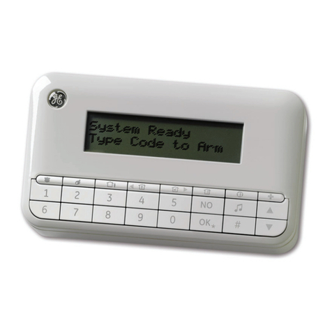
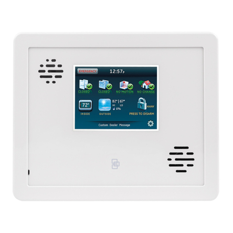
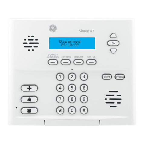
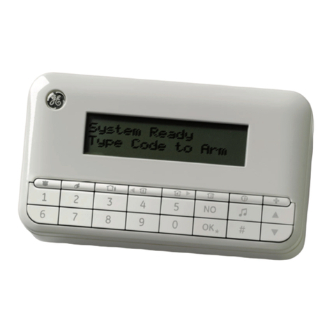
GE SIMON XT User manual

Simon XT Installation
Manual
P/N 466-2265-02 • REV C • ISS 01FEB11

Copyright © 2011 UTC Fire & Security. All rights reserved.
Trademarks and patents The Simon XT name and logo are trademarks of UTC Fire & Security.
GE and the GE monogram are trademarks of the General Electric
Company and are under license to Interlogix, a UTC Fire & Security
Company, 9 Farm Springs Road, Farmington, CT 06034-4065, USA
Other trade names used in this document may be trademarks or
registered trademarks of the manufacturers or vendors of the respective
products.
Manufacturer UTC Fire & Security Americas Corporation, Inc.
1275 Red Fox Rd., Arden Hills, MN 55112-6943, USA.
FCC compliance This equipment has been tested and found to comply with the limits for
a Class B digital device, pursuant to Part 15 of the FCC rules. These limits
are designed to provide reasonable protection against harmful
interference when the equipment is operated in a residential
environment. This equipment generates, uses, and can radiate radio
frequency energy and, if not installed and used in accordance with the
instruction manual, may cause harmful interference to radio
communications.
FCC Part 15 registration number: B4Z-910C-SIMON
IC: 1175C-910CSIMO
Part 68. This equipment complies with Part 68 of the FCC rules and the
requirements adopted by the ACTA.
FCC registration number: US: B4ZAK02B55910
Canada: 1175C-910SIXT
Ringer Equivalence 0.2B
Load Number 0.2
Contact information
For contact information, see
www.interlogix.com
www.utcfireandsecurity.com.

Content
Product overview 1
System components 2
Standard panel 4
Planning the installation 5
Planning sensor types and locations 5
Cross-zoning 9
System configuration 10
Installation 14
Connecting hardwired devices 15
Wiring a phone line to the panel 17
Wiring the power transformer 19
Programming 21
Menu navigation 23
Set clock 24
Set date 25
Revision 25
Contrast 26
System programming 26
Access codes 27
Security 27
Phone numbers 29
Phone options 29
Sensors 31
Reporting 33
Timers 35
Touchpad options 37
System options 38
Siren options 38
Piezo beep options 40
Audio verification options 41
System tests 42
Resetting memory to factory defaults 42
Testing 43
Control panel 43
Sensors 44
Phone communication 46
Simon XT Installation Manual i

Offsite phone operation 47
Central station communication 47
Two-way voice operation 48
Voice event notification 49
Troubleshooting 50
Specifications 52
Sensor names 53
Simon XT system quick reference 57
ii Simon XT Installation Manual

Product overview
This security system can be used as a fire warning system, an intrusion alarm system,
an emergency notification system, or any combination of the three. The system has
three types of components:
• Self-contained control panel
• Devices that report to the panel
• Devices that respond to commands from the panel
Figure 1: Simon XT system
SimonXT
123
45
6
789
0
Key fob Door/window sensor
PIR motion sensor
Smoke detector
Remote handheld
touchpad
Simon XT talking
touch sc reen
The self-contained panel provides the main processing unit for all system functions. It
receives and responds to signals from wireless sensors and wireless touchpads
throughout the premises. For monitored systems, the panel can be connected to the
premises phone line for central monitoring station reporting.
You can program the panel onsite from the keypad or remotely using Enterprise
Downloader software. See “Programming” on page 21 for complete onsite
programming instructions.
Simon XT Installation Manual 1

System components
The system can monitor up to 40 sensors and may use any of the devices listed in
Table 1 below.
Table 1: Supported devices
Device Description
Door/window sensor
(60-670, 60-362N)
For intrusion protection, install door/window sensors on all ground-
floor doors and windows. At a minimum, install then in the following
locations:
• All easily accessible exterior doors and windows.
• Interior doors leading into the garage.
• Doors to areas containing valuables.
Indoor motion sensor
(60-639)
Indoor motion sensors are ideal whenever it is not practical to
install door/window sensors on every opening. Identify areas where
an intruder is likely to walk through. Large areas in an open floor
plan, downstairs family rooms, and hallways are typical locations
for indoor motion sensors. For installations with pets, use the SAW
Pet Immune PIR (60-807).
Outdoor motion sensor
(60-639)
Use outdoor motion sensors to detect motion in a protected
outdoor area. Detected motion in this protected area can sound
chimes.
Freeze sensor
(60-742)
Freeze sensors detect low temperature conditions, which may
indicate a furnace failure. The sensor contains a bimetallic thermal
switch connected to the built-in transmitter. The sensor transmits
an alarm signal to the panel when the surrounding temperature
drops to about 41ºF (5ºC). When the temperature rises to 50ºF
(10ºC), the sensor transmits a restore signal.
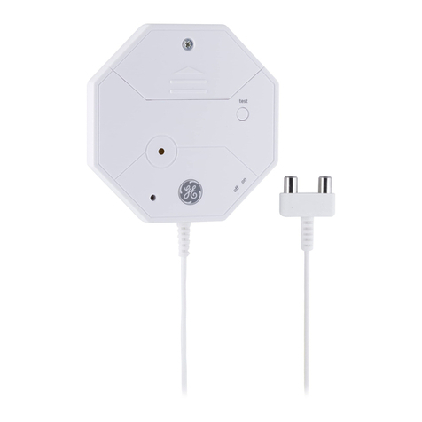
Water sensor
(60-744)
Water sensors detect water leaks and rising water. The detector is
connected to the sensor by an 8-foot cable. Water that reaches
both detector contact points activates the sensor, causing it to
transmit an alarm signal.
Smoke sensor
(60-848-02-95, TX-6010-01-1)
Smoke sensors provide fire protection by causing an alarm to
sound throughout the house. You can add smoke sensors near
sleeping areas and on every floor of the house. Avoid areas that
could have some smoke or exhaust such as attics, kitchens, above
fireplaces, dusty locations, garages, and areas with temperature
extremes. In these areas, you may want to install rate-of-rise
sensors to detect extreme temperature changes. See the
instructions packaged with the smoke sensor for complete
placement information.
Carbon monoxide (CO) alarm
(TX-6310-01-1)
The learn mode CO alarm alerts you to hazardous levels of carbon
monoxide gas. If dangerous concentrations of gas are present, the
red indicator light comes on, the internal siren goes off, and an
alarm is transmitted to the panel. The panel sounds its own alarm
and reports to the central station.
2 Simon XT Installation Manual

Device Description
Key fob
(60-659)
The key fob (keychain touchpad) lets you turn the system on and off
from right outside the home or activate a panic alarm if there is an
emergency. If you have the appropriate light control modules, you
can use key fobs to turn all system controlled lights on and off.
ELM (encrypted learn mode)
key fob
(60-832)
The ELM 2-button key fob is an alkaline battery-powered, wireless
touchpad that allows you to arm and disarm the system and
activate a police or auxiliary alarm. Random encrypted signal
transmissions provide high security to help prevent signal copying.
Remote handheld touchpad
(60-671)
The remote handheld touchpad lets you turn the system on and off
while in the home, turn system-controlled lights on and off, or
activate a panic alarm if there is a nonmedical emergency.
Simon XT talking touchpad
(60-924-3-XT)
The 2-way talking touchpad is a wireless device that provides a
convenient option to: arm the system (doors, windows, and motion
sensors), arm the system with no entry delay, disarm the system,
activate a panic alarm to call the central monitoring station in a
nonmedical emergency, check system status, and turn system
controlled lights on or off (all or individual), all while providing voice
feedback.
Simon XT talking touch screen
(60-924-3-XT-2WTTS,
60-924-RF-TS, 60-924-RF-TS-N)
The 2-way talking touch screen is a wireless device that provides a
graphical user interface that allows you to: arm the system (doors,
windows, and motion sensors), disarm the system, activate a panic
alarm to call the central monitoring station in a nonmedical
emergency, check system status, and turn system controlled lights
on or off, all while providing voice feedback. The touch screen also
provides trouble beeps, entry/exit beeps, and alarm sounds (Fire,
Aux., Police).
Water-resistant personal help
button
(60-906-95)
The water-resistant personal help button is a wireless device used
for activating police or auxiliary alarms through your system. When
the help button is pressed, the light mounted under the cover will
blink and an alarm signal is transmitted.
Caution: Do not use outdoor motion sensors for intrusion protection.
Simon XT Installation Manual 3

Standard panel
Table 2 below describes the basic panel (out-of-box) hardware capabilities for the
Simon XT 600-1054-95R-11 and 600-1054-95R-11-CN.
Table 2: Panel hardware capabilities
Hardware Capability
Power Input for an AC step-down, plug-in style transformer.
One siren output, up to two zone
inputs
Terminals for connecting hardware sirens or normally closed (NC)
loop switch circuits.
Phone line connection Allows the panel to communicate with the central monitoring
station and/or remote phone.
4 Simon XT Installation Manual

Planning the installation
This section describes system capabilities to help you get familiar with your system.
The planning sheets contain tables that let you record the hardware and
programming configuration of your system. Complete all of the information ahead of
time to help prepare for system installation. See “Sensor names” on page 53 for
sensor name segments listed alphabetically and by index number.
Locate the panel where alarm sounds can be heard and where the panel will be
easily accessible for operation. Do not install the panel near a window or door where
it can be reached easily by an intruder.
Planning sensor types and locations
The first step to an easy and successful installation is to decide what areas or items
to protect, which lights to operate, and the best location for the panel, touchpad,
sensors, and sirens. Metal objects, mirrors, and metallic wallpaper can block signals
sent by the wireless sensors. Make sure there are no metal objects in the way when
installing the system.
Use Table 3 below and Table 4 on page 6 to determine the appropriate sensor type
for the sensors you will be adding, and Table 5 on page 8 to document the planned
sensor information. You will need to understand the application for each sensor.
Table 3: Recommended sensor groups
Device Recommended sensor group
Indoor motion sensor 17 (intrusion), 25 (chime)
Outdoor motion sensor 25 (chime only)
Entry/exit door 10
Interior door 14
Window sensor 13
Smoke sensor 26
Key fob 01, 03, 06, 07
ELM key fob 01, 03, 06, 07
Remote and Simon XT talking touchpads 01, 03, 06, 07
Simon XT talking touch screen 00, 01, 04, 05, 06, 07
CO alarm 34
Freeze sensor 29
Water sensor 38
Property/asset management 43
Personal help button 01, 03, 06, 07
Simon XT Installation Manual 5

Table 4: Sensor group characteristics
Type
Name/application
Siren type
Dela
y
Restoral
Supervised
Active in
arming
levels
00 Fixed panic: 24-hour audible fixed emergency button. Intrusion I N Y 01234
01 Portable panic: 24-hour audible portable emergency
button.
Intrusion I N N 01234
02 Fixed panic: 24-hour silent fixed emergency button.
Status light will not blink.
Silent I N Y 01234
03 Portable panic: 24-hour silent portable emergency
buttons. Status light will not blink.
Silent I N N 01234
04 Fixed auxiliary: 24-hour auxiliary sensor. Emergency I N Y 01234
05 Fixed auxiliary: 24-hour emergency button. Siren shut
off confirms CS report.
Emergency I N Y 01234
06 Portable auxiliary: 24-hour portable auxiliary alert
button.
Emergency I N N 01234
07 Portable auxiliary 24-hour portable auxiliary button.
Siren shut off confirms CS report.
Emergency I N N 01234
08 Special intrusion: Such as gun cabinets and wall safes. Intrusion I Y Y 1234
09 Special intrusion: Such as gun cabinets and wall safes. Intrusion S Y Y 1234
10 Entry/exit delay: A delay that requires a standard delay
time. Chime.
Intrusion S Y Y 24
13 Instant perimeter: Exterior doors and windows. Chime. Intrusion I Y Y 24
14 Instant interior: Interior door. Intrusion F Y Y 234
15 Instant interior: Interior PIR motion sensor. Intrusion F Y Y 234
16 Instant interior: Interior door. Intrusion F Y Y 34
17 Instant interior: PIR motion sensor and sound sensor. Intrusion F N Y 34
18 Instant interior: Cross-zone PIR motion sensor. Intrusion F N Y 34
19 Delayed interior: Interior doors that initiate a delay
before going into alarm.
Intrusion S Y Y 34
20 Delayed interior: PIR motion sensor that initiates a delay
before going into alarm.
Intrusion S N Y 34
21 Local instant interior: 24-hour local alarm zone
protecting anything that opens and closes. No report.
Intrusion I Y Y 1234
22 Local delayed interior: Same as group 21, plus
activation initiates a delay before going into alarm. No
report.
Intrusion S Y Y 1234
23 Local instant auxiliary: 24-hour local alarm zone
protecting anything that opens and closes. No report.
Emergency I Y Y 01234
6 Simon XT Installation Manual

Type
Name/application
Siren type
Dela
y
Restoral
Supervised
Active in
arming
levels
24 Local instant auxiliary: 24-hour local alarm zone
protecting anything that opens and closes. Sirens shut
off at restoral. No report.
Emergency I Y Y 01234
25 Local special chime: Notify the user when a door is
opened.
Three beeps I N Y 01234
26 Fire: 24-hour fire, rate-of-rise heat, and smoke sensor. Fire I Y Y 01234
27 Lamp control or other customer feature. No report. Silent I Y Y 01234
28 PIR motion sensor, sound sensor, or pressure mat. RF
thermostat. No report
Silent I N Y 01234
29 Auxiliary: Freeze sensor. Trouble
beeps
I Y Y 01234
32 PIR motion sensor or sound sensor. No report. Silent I N N 01234
34 Carbon monoxide alarm. Emergency I Y Y 01234
35 Entry/exit delay interior PIR motion Intrusion S N Y 234
36 Special intrusion: Such as gun cabinets and wall safes.
Reports as tamper if tripped.
Intrusion I Y Y 1234
38 Auxiliary: Water sensor. Trouble
beeps
I Y Y 01234
39 Local instant interior: 24-hour local alarm zone
protecting anything that opens and closes. No report.
Intrusion I Y Y 1234
40 Local special chime. Three beeps I Y Y 01234
43 Property/asset management: Notify the user that a
protected asset has moved.
Note: We recommend you use this sensor group in
combination with a Two-Way Talking Touch Screen.
One beep I N Y 01234
Simon XT Installation Manual 7

Table 5: Sensor assignments/locations
Sensor # Device Sensor
group
Sensor name/location Notes
01
02
03
04
05
06
07
08
09
10
11
12
13
14
15
16
17
18
19
20
21
22
23
24
25
26
27
28
29
30
31
8 Simon XT Installation Manual

Sensor # Device Sensor
group
Sensor name/location Notes
32
33
34
35
36
37
38
39
40
Cross-zoning
Cross zoning (two-trip) refers to two different group 18 sensors that must be tripped
within two minutes of each other to report an alarm to the central station. Figure 2
below shows the path of a person walking from the kitchen to the living room. When
the person is detected walking through the kitchen, the motion sensor in the kitchen
is tripped, sounding a local alarm. If motion is detected by the living room motion
sensor within two minutes, an alarm report will be sent to the central station.
Figure 2: Cross-zone diagram
Motion sensor
Motion sensor
Path of person walking
Note: We do not recommend cross zoning for exit/entry zones. Each zone can
individually protect the intended area.
Simon XT Installation Manual 9

System configuration
Table 6 below is a worksheet for you to record the desired values for each
programming option. For each option, the default value, effect of deletion (pressing
Disarm while editing), range, and programming privilege are listed. Each option is
described in more detail in “Programming” on page 21.
In the table, the Access code column indicates what type of access code is allowed to
make changes: D = dealer code, I = installer code, M = master code.
Table 6: System programming menu options
Function Default Delete Range Access
code
Installer
settings
Access codes menu
Dealer code 654321, 54321,
4321, or 321
None 3 to 6 digits D
Installer code 654321, 54321,
4321, or 321
None 3 to 6 digits D, I
Master code 123456, 12345,
1234, or 123
None 3 to 6 digits D, I, M
User code 1 None None 3 to 6 digits D, I, M
User code 2 None None 3 to 6 digits D, I, M
User code 3 None None 3 to 6 digits D, I, M
User code 4 None None 3 to 6 digits D, I, M
User code 5 None None 3 to 6 digits D, I, M
User code 6 None None 3 to 6 digits D, I, M
User code 7 None None 3 to 6 digits D, I, M
User code 8 None None 3 to 6 digits D, I, M
Duress code None None 3 to 6 digits D, I, M
Code length 4 4 3 to 6 D
Security menu
Account number 00000 00000 0 to FFFFFFFFFF D, I
Downloader code 12345 12345 00000 to 99999 D
Phone lock Off Off On/Off D
Auto arm On Off On/Off D, I
Exit extension On Off On/Off D, I
Secure arming Off Off On/Off D, I
No arm low battery Off Off On/Off D, I
Quick exit Off Off On/Off D, I
10 Simon XT Installation Manual

Function Default Delete Range Access
code
Installer
settings
Downloader enable On Off On/Off D, I, M
Supervisory protest Off Off On/Off D, I
Phone # menu
Phone #1 None None 26 digits D
Phone #2 None None 26 digits D
Phone #3 None None 26 digits D, I
Phone #4 None None 26 digits D, I, M
Downloader # None None 26 digits D, I
Phone options menu
Manual phone test On Off On/Off D, I
Fail to communicate On Off On/Off D, I
DTMF On (touchtone) Off (pulse) On/Off D, I
300 bps baud rate On (300 bps) Off (110 bps) On/Off D, I
Ring/hang/ring 1 Off 1 to 7, Off D, I
Dial delay 30 seconds 15 seconds 15 to 45 seconds D, I
Call waiting code None None 26 digits D, I
Line cut detect Not available
Sensors menu
Learn sensors D, I
Delete sensors D, I
Edit sensors D, I
Reporting menu
Report options
Opening reports Off Off On/Off D, I
Closing reports Off Off On/Off D, I
Forced armed Off Off On/Off D, I
AC power failure
report
Off Off 5 to 254 minutes,
off
D, I
Low CPU battery
report
On Off On/Off D, I
Sensor alarm restoral
report
Off Off 1 to 3, Off D, I
24-hour sensor
tamper report
Off Off On/Off D, I
Simon XT Installation Manual 11

Function Default Delete Range Access
code
Installer
settings
Supervisory/ tamper
report
Off Off On/Off D, I
No usage Off Off 2 to 254 days, Off D, I
Swinger shutdown On Off On/Off D, I
Programming report Off Off On/Off D, I
Fire alarm verification Off Off On/Off D, I
Report communication modes
Phone 1 report mode Off Off D
Phone 2 report mode Off Off D
Phone 3 report mode Off Off D, I
Phone 4 report mode Off Off
All SIA, All CID,
Alarms SIA, Alarms
CID, Nonalarm SIA,
Nonalarm CID,
Backup SIA,
Backup CID, Voice
dialer, or Off
D, I
Timers menu
Latchkey time None None 12:00 midnight to
11:59 PM, None
D, I, M
Entry delay 30 seconds 30 seconds 30 to 240 seconds D, I
Exit delay 60 seconds 45 seconds 45 to 254 seconds D, I
No activity timeout Off Off 2 to 24 hours, off D, I
Auto phone test Off Off 1 to 254 days, off D, I
Supervisory time Midnight None 12:00 midnight to
11:59 PM, None
D, I
Alarm cancel 6 minutes Off 6 to 255 minutes,
Off
D, I
RF timeout 12 hours 12 hours 2 to 36 hours D, I
Fail to open time Off Off 12:00 midnight to
11:59 PM, Off
D, I
Fail to close time Off Off 12:00 midnight to
11:59 PM, Off
D, I
Siren timeout 5 minutes Off 2 to 254 minutes,
Off
D, I
Arming LED shutdown Off Off On/Off D, I
Unvacated premises On Off On/Off D, I
Smoke supervision Off Off On/Off D, I
Touchpad options menu
Key fob no delay Off Off On/Off D, I
Panic alarms On Off On/Off D, I
12 Simon XT Installation Manual

Function Default Delete Range Access
code
Installer
settings
Remote touchpad
arming
Off Off On/Off D, I
System options menu
RF jam detect Off Off On/Off D, I
Demo mode Off Off On/Off D, I
HW1 function 1 Off 1, 2, 3, 4, 5, or Off D
24-hour clock Off Off On/Off D, I
Siren options menu
Panel piezo beeps On Off On/Off D, I, M
Panel voice On Off On/Off D, I, M
Panel piezo alarms On Off On/Off D, I, M
Trouble beeps On Off On/Off D, I
Voice chime Off Off 1, 2, 3, or Off D, I
Status beeps volume 7 7 1 to 10 D, I, M
Hardwired siren
supervision
Off Off On/Off D, I
Speaker volume 8 8 1 to 8 D, I, M
Panel silent police
panic
Off Off On (silent), Off
(audible)
D, I
Alarm report
verification
Off Off On/Off D, I
Audio verify menu
Audio mode Off Off 1, 2, or Off D, I
Fire shutdown Off Off On/Off D, I
Panic talk Off Off On/Off D, I
Vox receiver gain 6 6 1 to 32 D, I
Vox mic gain 24 24 1 to 64 D, I
Vox mic gain range 64 64 1 to 64 D, I
Manual mic gain 64 64 1 to 64 D, I
System test menu
Sensor test D, I, M
Communication test D, I, M
System download D, I, M
Simon XT Installation Manual 13

Installation
Tabs at the top of the panel secure and release the front cover and the chassis. The
plastic hinges on the panel bottom allow the cover and chassis to swing down and
out of the way.
To mount the panel on a wall:
1. Choose a panel location and run all necessary power, phone, siren, and hardwired
contact wires to the desired location.
When choosing the AC outlet location for the AC power transformer, make sure
the outlet is not controlled by a switch or that it is not part of a ground fault circuit
interrupt (GFCI).
2. Hold the panel against the wall and mark the mounting hole locations with a
pencil (see Figure 3 below).
3. Mount the back piece to the wall through the two horizontally centered mounting
holes near the top and bottom using the supplied mounting hardware. Use wall
anchors if no studs are present.
4. Connect the chassis assembly to the mounted back piece and let it hang down.
This makes the terminal strip accessible for wiring various hardwired components
to the panel.
5. Feed wires through opening in the back piece to be ready to attach them to the
screw terminals or the phone connectors.
6. Install all screws and tighten gently.
Figure 3: Mounting holes
Mounting hole
Mounting hole
Wiring knockout
14 Simon XT Installation Manual

Connecting hardwired devices
The panel has five screw terminals, two battery terminals, and two telephone
connections. The screw terminals connect the AC power, sirens, and or hardwired
detectors.
Figure 4: Wiring terminals
12345
1 HW1 I/O
2 HW1&2 DC out
3 HW2 in
4 9 VAC in
5 9 VAC in
Program sensors and devices before you install them. Follow the instructions in
“Sensors” on page 31 to add the sensors to panel memory.
The HW1 I/O terminal is dual purpose and can be used for either siren or hardwired
contact connections. The HW2 in terminal is an input only.
Interior sirens
From the factory, the HW1 I/O input is set up for interior siren operation (status and
alarm sounds). The HW1&2 DC out terminal provides the positive (+) voltage.
Note: The total current available from the HW1&2 DC out terminal is 250 mA at up to
120ºF (49ºC). A 24-hour battery standby will be met with a maximum load of 250 mA.
With hardwired siren supervision turned on, sirens connected to HW1 I/O are
supervised and require a 4.7-kohm resistor in the circuit. If this terminal is not used,
turn hardwired siren supervision off.
Hardwired interior siren
Interior sirens must always be wired with a resistor in the circuit. For circuit
supervision, which allows the panel to detect if the siren wire is cut (open), the
hardwired siren supervision option must be turned on.
Note: Do not install the resistor at the panel terminals. This does not provide
supervision of the wire.
Connect the hardwired interior siren (13-374) to the panel using a 4.7 kohm resistor
(included with the siren) as shown in Figure 5 on page 16. The resistor must be
connected across the siren wires as close to the siren as possible.
Simon XT Installation Manual 15
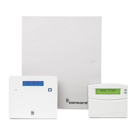
Figure 5: Hardwired interior siren with supervision
12345
1 HW1 I/O
2 HW1&2 DC out
4.7 kohm resistor
(located at siren)
Black Red
Exterior sirens
For an exterior siren, reprogram HW1 to Option 6. See Wiring diagram.
Hardwired contacts
To set up HW1 I/O and/or HW2 for hardwired contacts, make the required
connections described below, and then proceed to “Programming” on page 21 to add
(learn) them into panel memory.
You can connect hardwired reed switches (normally closed loop only) to HW1 I/O (if
not being used for a hardwired siren) and/or HW2 in.
Note: Connect only normally closed (NC) reed switches to HW1 I/O and/or HW2 in.
Other types of hardwired detectors should not be used.
The total resistance of the wired loop must not exceed 3 ohms. This allows you to use
up to 200 ft. (61 m) of two-conductor, 22-gauge stranded wire.
Connect hardwired reed switches to the panel using a 47-kohm resistor (not a 4.7-
kohm resistor) as shown in Figure 6 on page 17. The resistor must be connected at
the last switch in the circuit.
16 Simon XT Installation Manual
Other manuals for SIMON XT
11
Table of contents
Other GE Security System manuals
Popular Security System manuals by other brands

DSC
DSC PC 5010 quick guide

LG
LG iCAM4000 quick start guide

Skyros
Skyros VideoNet 9.1 installation manual

Texecom
Texecom Ricochet Impaq Contact-W user manual
AEI Security & Communications
AEI Security & Communications 3400 Installation & operation manual

AVS Electronics
AVS Electronics TS85 V LED Plus GENERAL MANUAL FOR INSTALLATION

Omega
Omega MAX-EDP Operation manual

Kidde
Kidde P4010ACSCOAQ-WF user guide

Swann
Swann DVRx-2500 Setup guide

alsident
alsident SYSTEM10 Mounting and instruction manual

Visonic
Visonic PowerMaster-10 G2 Quick user guide

Pittway
Pittway SYSTEM SENSOR SPECTRAlert SC2415W Installation and maintenance instructions