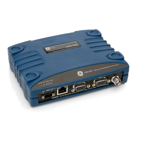
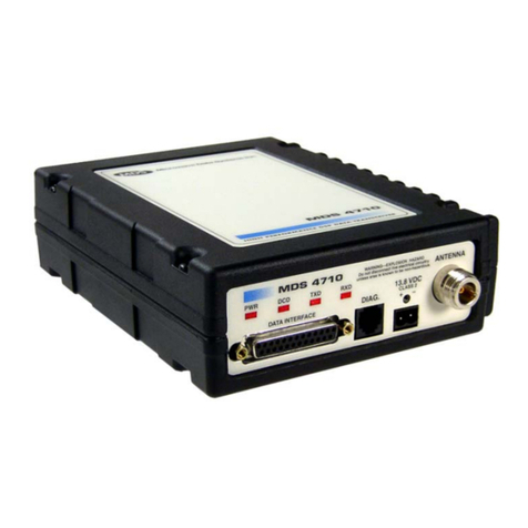
GE MDS SD Series User manual

MDS™ SD Series
Secure, Long Range IP/Ethernet & Serial
Covering ES/SS Units with Firmware Version 5.4.0
Applies to all modes EXCEPT those operated in x710 Mode.
For x710 mode operation, refer to Publication 05-4670A01.
MDS 05-4846A01, Rev. J
JUNE 2016
Technical Manual

Quick-Start instructions for this product are contained in publication 05-4847A01.
Visit our website for downloadable copies of all documentation at www.gemds.com.

TABLE OF CONTENTS
1.0 INTRODUCTION...................................................................................................................................1
1.1 Conventions Used in This Manual ........................................................................................................1
1.2 New Features in this Release...............................................................................................................2
2.0 PRODUCT DESCRIPTION...................................................................................................................3
2.1 Front Panel Connectors and Indicators.................................................................................................3
2.2 Key Product Features............................................................................................................................3
Media Access Control (MAC)...........................................................................................................4
VLAN Capability...............................................................................................................................5
Terminal Server Capability...............................................................................................................5
Store and Forward Capability ..........................................................................................................5
Peer-to-Peer Capability....................................................................................................................5
Tail End Network Capability.............................................................................................................5
Frequency Re-use (System ID) .......................................................................................................5
2.3 SD Model Offerings...............................................................................................................................6
2.4 Operating Modes and Applicable Manuals ...........................................................................................6
2.5 Accessories and Spares........................................................................................................................7
Protected Network Station ...............................................................................................................8
2.6 MDS™ Master Station Compatibility.....................................................................................................8
3.0 TYPICAL APPLICATIONS...................................................................................................................9
3.1 Operating Parameters...........................................................................................................................9
3.2 Example Systems................................................................................................................................10
Multiple Address Systems (MAS) ..................................................................................................10
Point-to-Point System ....................................................................................................................11
IP Payload/Ethernet Polling and Terminal Server Operation ........................................................11
Port Sharing with Multiple Hosts....................................................................................................12
Push Communication (Report-by Exception).................................................................................13
IP Polling of Serial Remotes ..........................................................................................................14
IP Polling of Two Serial Ports on One Remote..............................................................................14
4.0 INSTALLATION PLANNING..............................................................................................................16
4.1 Chassis Dimensions............................................................................................................................16
4.2 Mounting Bracket Options...................................................................................................................17
Optional DIN Rail Mounting ...........................................................................................................17
4.3 Antennas and Feedlines......................................................................................................................18
Antennas........................................................................................................................................18
Feedlines..........................................................................................Error! Bookmark not defined.
4.4 DC Power Connection.........................................................................................................................19
4.5 Grounding Considerations...................................................................................................................20
4.6 Ethernet Data Interface (RJ-45)..........................................................................................................20
4.7 Serial Data Interfaces..........................................................................................................................21
COM1 (Serial) Connection.............................................................................................................21
COM2 (Data) Connections.............................................................................................................22
5.0 STEP-BY-STEP INSTALLATION.......................................................................................................25
5.1 Initial Configuration..............................................................................................................................25
Web-Based Management ..............................................................................................................26
Web Browser Connection ..............................................................................................................26
Alternative Management Methods .................................................................................................29
5.2 Initial Startup & Checkout....................................................................................................................29
Ethernet Connector LEDs..............................................................................................................30
5.3 Optimizing the Radio Network.............................................................................................................30
Modem Type Setting......................................................................................................................30
MDS 05-4846A01, Rev. J SD Series Technical Manual i
Inter-Packet Gap Settings..............................................................................................................30
Baud Rate Setting..........................................................................................................................30
Ethernet Settings............................................................................................................................31
Antenna SWR Check.....................................................................................................................31
6.0 USING THE DEVICE MANAGER.......................................................................................................32
6.1 Navigating the Screens.......................................................................................................................32
Overview Screen............................................................................................................................33
6.2 Management Tasks.............................................................................................................................34
6.3 Configuration Screens.........................................................................................................................39
Radio..............................................................................................................................................40
Media Access Control....................................................................................................................45
Store and Forward Operation ........................................................................................................45
Features.........................................................................................................................................50
Understanding the Use of Virtual Radio Channels (VRCs) ...........................................................55
Using the Terminal Server — Typical Example.............................................................................57
Communications Ports...................................................................................................................62
Security ..........................................................................................................................................66
6.4 Maintenance & Status Screens...........................................................................................................68
Event Log.......................................................................................................................................69
Alarm Summary .............................................................................................................................69
Performance...................................................................................................................................71
Firmware Utilities............................................................................................................................77
Configuration Files .........................................................................................................................81
7.0 TROUBLESHOOTING........................................................................................................................83
7.1 LED Indicators.....................................................................................................................................84
7.2 Checking for Alarms/Events................................................................................................................85
Major Alarms vs. Minor Alarms......................................................................................................85
Status and Informational Events....................................................................................................85
Event Code Definitions...................................................................................................................85
7.3 Operating Constraints .........................................................................................................................87
8.0 TECHNICAL REFERENCE ................................................................................................................89
8.1 Performing Network-Wide Remote Diagnostics..................................................................................89
Setting Up Diagnostics...................................................................................................................90
8.2 Over-the-Air Firmware Upgrades........................................................................................................90
Intrusive vs. Passive (Non-Intrusive) Mode ...................................................................................90
Broadcast Reprogramming Suggestions by Network Type...........................................................92
OTA Reprogramming Overview.....................................................................................................92
Cancelling OTA Reprogramming...................................................................................................93
Error Conditions/Recovery.............................................................................................................93
Execution and Screen Examples...................................................................................................93
8.3 COM1 Operating Modes .....................................................................................................................94
Changing COM1 Modes.................................................................................................................94
8.4 Implementing Sleep Mode...................................................................................................................95
8.5 Technical Specifications......................................................................................................................96
8.6 dBm-Watts-Volts Conversion Chart ....................................................................................................98
9.0 GLOSSARY OF TERMS & ABBREVIATIONS..................................................................................99
ii SD Series Technical Manual MDS 05-4846A01, Rev. J

Copyright and Trademark
This manual and all software described herein is protected by Copyright: 2015 GE MDS, LLC.
All rights reserved. GE MDS, LLC reserves its right to correct any errors and omissions in this
publication. Modbus® is a registered trademark of Schneider Electric Corporation. All other
trademarks and product names are the property of their respective owners.
RF Safety Notice (English and French)
Concentrated energy from a directional antenna may pose a health hazard to
humans. Do not allow people to come closer to the antenna than the distances
listed in the table below when the transmitter is operating. More information
on RF exposure can be found online at the following website:
www.fcc.gov/oet/info/documents/bulletins.
Concentré d'énergie à partir d'une antenne directionnelle peut poser un risque
pour la santé humaine. Ne pas permettre aux gens de se rapprocher de l'an-
tenne que les distances indiquées dans le tableau ci-dessous lorsque l'émetteur
est en marche. Plus d'informations sur l'exposition aux RF peut être trouvé en
ligne à l'adresse suivante: www.fcc.gov/oet/info/documents/bulletins.
Antenna Gain vs. Minimum RF Safety Distance
Antenna Gain
0–5 dBi 5–10 dBi 10–16.5 dBi
Safety Distance (SD4) 0.79 meter 1.41 meters 3.05 meters
Safety Distance (SD9) 0.46 meter .82 meters 1.74 meters
Safety Distance (SD1)
For SD1, maintain an RF safety distance of
1.80 meters for a 7 dBd (9.15 dBi) antenna.
Use of higher gain antennas means
increasing the distance accordingly.
Safety Distance (SD2)
For SD2, maintain an RF safety distance of
1.50 meters for a 7 dBd (9.15 dBi) antenna.
Use of higher gain antennas means
increasing the distance accordingly.
Safety Distance
(other models):
Consult factory prior to operation.
FCC Part 15 Notice
Operation is subject to the following two conditions: (1) this device may not cause harmful inter-
ference, and (2) this device must accept any interference received, including interference that
may cause undesired operation. Any unauthorized modification or changes to this device without
the express approval of the manufacturer may void the user’s authority to operate this device.
Furthermore, this device is intended to be used only when installed in accordance with the in-
structions outlined in this manual. Failure to comply with these instructions may void the user’s
authority to operate this device.
MDS 05-4846A01, Rev. J SD Series Technical Manual iii

Industry Canada Notice
This Class A digital apparatus complies with Canadian ICES-003.
Cet appareil numérique de la classe A est conforme à la norme NMB-003 du Canada.
Servicing Precautions
When servicing energized equipment, be sure to wear appropriate Personal Protective Equipment
(PPE). During internal service, situations could arise where objects accidentally contact or short
circuit components and the appropriate PPE would alleviate or decrease the severity of potential
injury. When servicing radios, all workplace regulations and other applicable standards for live
electrical work should be followed to ensure personal safety.
Manual Revision and Accuracy
This manual was prepared to cover a specific version of firmware code. Accordingly, some
screens and features may differ from the actual unit you are working with. While every reasona-
ble effort has been made to ensure the accuracy of this publication, product improvements may
also result in minor differences between the manual and the product shipped to you. If you have
additional questions or need an exact specification for a product, please contact GE MDS using
the information at the back of this guide. In addition, manual updates can be found on our web
site at www.gemds.com
Environmental Information
The manufacture of this equipment has required the extraction and use of natural resources. Im-
proper disposal may contaminate the environment and present a health risk due to hazardous
substances contained within. To avoid dissemination of these substances into our environment,
and to limit the demand on natural resources, we encourage you to use the appropriate recycling
systems for disposal. These systems will reuse or recycle most of the materials found in this
equipment in a sound way. Please contact GE MDS or your supplier for more information on the
proper disposal of this equipment.
Battery Disposal —This product may contain a battery. Batteries must be disposed of properly,
and may not be disposed of as unsorted municipal waste in the European Union. See the product
documentation for specific battery information. Batteries are marked with a symbol, which may
include lettering to indicate cadmium (Cd), lead (Pb), or mercury (Hg). For proper recycling re-
turn the battery to your supplier or to a designated collection point. For more information see:
www.weeerohsinfo.com.
Product Test Data Sheets —Test Data Sheets showing the original factory test results for this
unit are available upon request from the GE MDS Quality Leader. Contact the factory using the
information at the back of this manual. Serial numbers must be provided for each product where
a Test Data Sheet is required.
CSA/us Notice
This product is approved for use in Class 1, Division 2, Groups A, B, C & D Hazardous Loca-
tions. Such locations are defined in Article 500 of the National Fire Protection Association
(NFPA) publication NFPA 70, otherwise known as the National Electrical Code. The transceiver
has been recognized for use in these hazardous locations by the Canadian Standards Association
iv SD Series Technical Manual MDS 05-4846A01, Rev. J

(CSA) which also issues the US mark of approval (CSA/US). The CSA Certification is in accord-
ance with CSA STD C22.2 No. 213-M1987.
CSA Conditions of Approval: The transceiver is not acceptable as a stand-alone unit for use in
the hazardous locations described above. It must either be mounted within another piece of
equipment which is certified for hazardous locations, or installed within guidelines, or conditions
of approval, as set forth by the approving agencies. These conditions of approval are as follows:
The transceiver must be mounted within a separate enclosure which is suitable for the intended
application. The antenna feed line, DC power cable and interface cable must be routed through
conduit in accordance with the National Electrical Code. Installation, operation and maintenance
of the transceiver should be in accordance with the transceiver's installation manual, and the Na-
tional Electrical Code. Tampering or replacement with non-factory components may adversely
affect the safe use of the transceiver in hazardous locations, and may void the approval. A power
connector with screw-type retaining screws as supplied by GE MDS must be used.
Do not disconnect equipment unless power has been switched off or the area is known
to be non-hazardous. Refer to Articles 500 through 502 of the National Electrical Code
(NFPA 70) for further information on hazardous locations and approved Division 2 wir-
ing methods.
ATEX Directive Compliance Information
The SD wireless transceivers are ATEX Compliant with the “Zone 2, Cat 3"
requirements pending the proper installation requirements listed below.
Do not disconnect while circuit is Live unless area is known to be non-hazardous. Do not open when ener-
gized.
The SD product was evaluated based on the following ratings as per SIRA 15ATEX4251X and
IECEx CSA 15.0035X:
• II 3 G
• Ex nA IIA T3 Gc
• Amb -40°C to +70°C
• T3
MDS 05-4846A01, Rev. J SD Series Technical Manual v

Decoded:
• II - Equipment Group - Electrical equipment intended for use in places with an explosive
gas atmosphere other than mines susceptible to firedamp
• 3 G - Zone 2 - Normal Protection level Gas - Provides a low level of protection and is in-
tended for use in a Zone 2 hazardous area
• Ex nA - Gas & Air Mixture Zone 2 protection - Non-Sparking
• IIA - Gas Group IIA - Propane
• T3 - temperature classification
• Gc - Gas atmospheres - assured level of protection against becoming an ignition source
in normal operation
ATEX Special Conditions for Safe Use:
1. The device shall be installed in an additional enclosure that provides an ingress protection
rating not less than IP54 and meets the enclosure requirements of EN 60079-0 and
EN 60079-15. Any field wiring connections or cable entries used for this outer enclosure
shall also be suitably certified against the enclosure requirements of EN 60079-0 and EN
60079-15. The installer shall ensure that the maximum ambient temperature of the module
when installed is not exceeded.
2. The equipment shall only be used in an area of not more than pollution degree 2, as defined
in IEC 60664-1.”
3. Transient protection shall be provided that is set at a level not exceeding 140 % of the peak
rated voltage value at the supply terminals to the equipment.
Standards of Compliance
1999/5/EC RTTE Directive 1999/5/EC
2004/108/EC EMC Directive 2004/108/EC
2006/95/EC Low Voltage Directive, LVD. 2006/95/EC
2011/65/EC Restriction of the use of certain hazardous 2011/65/EC
substances in electrical and electronic equipment
EN 300 113-2 Radio Equipment and System specifications V1.5.1
EN60950-1:2006 Safety of Information technology equipment 1:2006
+A12:2011
EN 301 489-1 Electromagnetic compatibility V1.9.2
EN60079-0:2012/A11:2013 Equipment for Explosive Atmospheres
& EN 60079-15:2010
BSD License Information
The SD Series products contain source code originally released as part of “WPA Supplicant”
which is copyrighted as indicated below and is redistributed under the terms of the BSD license:
vi SD Series Technical Manual MDS 05-4846A01, Rev. J

WPA Supplicant
All Rights Reserved.
BSD License
-------
Redistribution and use in source and binary forms, with or without modification, are permitted
provided that the following conditions are met:
1. Redistributions of source code must retain the above copyright notice, this list of conditions
and the following disclaimer.
2. Redistributions in binary form must reproduce the above copyright notice, this list of condi-
tions and the following disclaimer in the documentation and/or other materials provided with the
distribution.
3. Neither the name(s) of the above-listed copyright holder(s) nor the names of its contributors
may be used to endorse or promote products derived from this software without specific prior
written permission.
THIS SOFTWARE IS PROVIDED BY THE COPYRIGHT HOLDERS AND CONTRIBU-
TORS “AS IS” AND ANY EXPRESS OR IMPLIED WARRANTIES, INCLUDING, BUT
NOT LIMITED TO, THE IMPLIED WARRANTIES OF MERCHANTABILITY AND FIT-
NESS FOR A PARTICULAR PURPOSE ARE DISCLAIMED. IN NO EVENT SHALL THE
COPYRIGHT OWNER OR CONTRIBUTORS BE LIABLE FOR ANY DIRECT, INDIRECT,
INCIDENTAL, SPECIAL, EXEMPLARY, OR CONSEQUENTIAL DAMAGES (INCLUD-
ING, BUT NOT LIMITED TO, PROCUREMENT OF SUBSTITUTE GOODS OR SERVICES;
LOSS OF USE, DATA, OR PROFITS; OR BUSINESS INTERRUPTION) HOWEVER
CAUSED AND ON ANY THEORY OF LIABILITY, WHETHER IN CONTRACT, STRICT
LIABILITY, OR TORT (INCLUDING NEGLIGENCE OR OTHERWISE) ARISING IN ANY
WAY OUT OF THE USE OF THIS SOFTWARE, EVEN IF ADVISED OF THE POSSIBIL-
ITY OF SUCH DAMAGE.
MDS 05-4846A01, Rev. J SD Series Technical Manual vii


1.0 INTRODUCTION
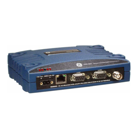
This manual is one of two publications for users of the MDS SD Series Transceiver shown in
Figure 1. It contains an overview of common applications, installation planning data, specifica-
tions, troubleshooting, and instructions for using the web-based Device Manager. This manual is
intended for technical personnel who perform network design, configuration, and troubleshoot-
ing of the equipment.
A companion Setup Guide is also available (Part no. 05-4847A01). The scope of the Setup Guide
is limited to installing the transceiver and placing it in service for the first time. All product doc-
umentation can be downloaded free of charge from the GE MDS website at www.gemds.com. The
website also contains links to Application Bulletins and other product information.
Figure 1. MDS SD Series Transceiver
1.1 Conventions Used in This Manual
Software & Device Manager Notations
This product is designed for software control via a connected PC. To show the names of screen
items, keyboard entries, or other information displayed on a PC, a bolded font is used throughout
the manual that appears as follows:
Bolded font example (for screen names and keyboard entries)
To show the navigation path leading to a particular screen, this same font is used with forward-
pointing arrows between screen names. For example, suppose you wish to access the radio’s Fea-
tures Screen. The navigation path shown for it would appear as follows:
Configuration>>Features
Model Number Notations
The term “SD” or “SD Series” is used in this manual to denote all models in the SD product line.
Specific model numbers such as MDS SD1 (150-174 MHz), SD2 (216-235 MHz), SD4 (300-512
MHz), and SD9 (820-960 MHz) are used only when necessary to reference model-specific fea-
tures.
Authorization Features
Some features of the radio are dependent on purchased options and applicable regulatory con-
straints. A “key” icon is shown near the heading of any such features. In some cases a fea-
ture upgrade may be available. Contact your sales representative for additional information.
MDS 05-4864A01, Rev. I SD Series Technical Manual 1

1.2 New Features in this Release
The SD transceiver has been updated to include the following functionality in the latest release
of the product:
• Over-the-Air Compression to maximize bandwidth (See Page 44)
• Internal Modbus TCP to RTU Conversion added for IP Payloads (see Page 56)
• CTS Key Support for Packet and Packet w/MAC modes (see Page 64)
• VLAN Gateway for each IP Configuration when VLANs are enabled (see Page 66)
• 600bps baud rate added to COM ports (see page 64)
• Tail End Network Support when in Packet w/MAC Mode (AP only) (See Page 45)
• Modem Transmit Tolerance feature to enhance over-the-air data when using 38400N,
19200N and 4800F modems. (See Page 50)
• Added Buffer Delay to the COM2 port (see page 63)
• Added option for Seamless Support while in Transparent Mode (see page 65)
2 SD Series Technical Manual MDS 05-4846A01, Rev. I

2.0 PRODUCT DESCRIPTION
The transceiver is a software-configurable, industrial radio for use in licensed data acquisition
networks. It may be interfaced with a variety of data control equipment including remote termi-
nal units (RTUs), programmable logic controllers (PLCs), flow computers, and similar devices.
Data interface connections may be made for both serial (RS-232/RS-485) and Ethernet protocols.
It is designed for use in both polled networks and report-by-exception (push) systems.
The radio employs digital signal processing (DSP) technology and a fully digital transmit and
receive IF chain to provide robust communications even under adverse conditions. DSP technol-
ogy also helps eliminate the effects of component variations or temperature changes, resulting in
optimized performance.
2.1 Front Panel Connectors and Indicators
Figure 2 shows the transceiver’s front panel connectors and indicators. These items are refer-
enced in the installation steps and in various other locations in the manual. The transceiver’s
LED functions are described in Table 10 on Page 29.
Figure 2. Front Panel Connectors & Indicators
2.2 Key Product Features
The transceiver is designed to meet the demanding needs of today’s wireless networks in a com-
pact and rugged package. It offers an array of features in a single hardware platform:
• Software-configurable via a built-in Device Manager — no manual controls or adjustments.
• Media Access Control (MAC) to prevent data collisions when two or more radios try to use
the radio channel at the same time.
• Available encryption of payload data (AES 128-bit)
• Supports Virtual LAN (VLAN) operation
MDS 05-4864A01, Rev. I SD Series Technical Manual 3

• Terminal Server capability to enable IP addressing of serial interface ports on individual ra-
dios
• Store and Forward capability
• Frequency Re-use that offers approximately 20 dB of additional co-channel isolation when
operating networks on the same frequency.
• Supports use of MDS™ PulseNET Network Management Software
• Supports a wide variety of modem speeds and bandwidths for regulatory compliance in vir-
tually all regions of the world
• Ethernet & serial interfaces — ideal for migration to IP networks
• Dual serial functionality (RS-232 and RS-485)
• Modbus TCP to RTU Conversion in both Terminal Server and IP Payload features elimi-
nates the need for extra equipment.
• Over-the-air reprogramming of remote units — no unnecessary trips to radio sites
• Licensed 5-watt design, maximizes communications range with low interference risk from
other users
• Configurable via software as a Remote or an AP unit
• Low power “sleep mode” — ideal for battery-powered solar sites
• Virtual Radio Channels (VRC) support multiple polling applications on one radio
NOTE Some features may not be available on all units, depending on the options purchased and
regulatory constraints for the region in which the radio will operate.
Media Access Control (MAC)
An important feature of the transceiver is Media Access Control (MAC). The radio’s MAC is
specifically designed for use with narrow bandwidth, half duplex radio networks such as those
commonly used in licensed telemetry systems. When the MAC is enabled, it provides efficient
support of multiple data traffic models including multiple hosts, synchronous and asynchronous
polls, and report-by-exception (push traffic). MAC ensures that every transceiver in the network
has an equal probability of gaining access to the radio channel when it has data to send.
Coordination of Channel Access
The main objective of the MAC is to coordinate channel access for all radios in the network,
preventing data “collisions” that can occur with simultaneous transmissions from radios on the
same RF channel. With MAC operation, a single radio is configured as an Access Point (AP) and
other units are designated as Remotes. The AP serves as the controller of the RF network. Re-
motes request permission from the AP to use the RF channel before sending payload data, thus
avoiding collisions of data, and creating a highly reliable wireless network. The MAC is respon-
sible for allocating which unit gets access to the broadcast medium (the RF channel), when, and
for how long.
Data Validation
Additionally, the MAC validates all messages and purges corrupted data from the system. Suc-
cessful delivery of data is ensured through the use of retries and acknowledgements. Minimal
overhead is used to accomplish these tasks, which translates to increased bandwidth efficiency of
the radio channel with minimal latency, ensuring that messages are delivered in a timely manner.
4 SD Series Technical Manual MDS 05-4846A01, Rev. I

VLAN Capability
A Virtual Local Area Network (VLAN) is essentially a limited broadcast domain, meaning that
all members of a VLAN receive broadcast frames sent by members of the same network, but not
frames sent by members of a different network.
The radio supports port-based VLAN at the Ethernet interface and over the air, in accordance
with the IEEE 802.1Q standard. When VLAN Mode is enabled, the wireless ports of both AP
and Remote radios act as a “trunk port” to carry data.
Terminal Server Capability
The unit’s Terminal Server option allows serial port data to be sent over the air in the form of IP
packets. It works by encapsulating data from the serial (COM1/COM2) ports as IP packets, then
transmitting it over the air. At the receiving end, the data is decapsulated and delivered to the ap-
propriate COM port. The Terminal Server option provides a front-end RTU conversion for TCP
MODBUS Data. See “Terminal Server COM1/2 Configuration” on Page 56 for more infor-
mation.
Store and Forward Capability
Store and Forward (SAF) capability is only available in Packet w/MAC mode. It allows a radio
to store incoming data and retransmit it a short time later to other stations. This can be used to
link outlying Remote stations to the AP when direct communication is not possible due to ter-
rain, distance, or other obstructions.
Communication routes are automatically discovered and traffic is intelligently filtered such that
only store and forward traffic is sent through the SAF unit, conserving critical bandwidth in the
network.
Peer-to-Peer Capability
Peer to Peer capability is available in Packet w/MAC mode only. It allows Remote radios in the
same radio network to pass data indirectly between each other via the AP. When the Peer-to-Peer
functionality is enabled on the Remote, both the Remote and the AP will be able to pass data in
the system. The AP will route data to and from the enabled peers without disrupting AP-to-
Remote specific communications.
Tail End Network Capability
This feature allows the user to send DLINK messages across networks when two radios are con-
nected via the COM1 port (Note that a special cable wiring is required to connect the radios in
the tail-end link). This feature allows Network Monitoring to extend to the Tail end link Network
when operating in Packet w/MAC mode.
Frequency Re-use (System ID)
Frequency Re-use is possible in some applications. SysID (or System ID as it is referred to in the
Device Manager) offers approximately 20 dB of additional co-channel isolation when operating
networks on the same frequency (see Page 41 for more information). Note that proper system
design is required. SysID offers nine unique choices including the default value of NONE. Master
and Remote radios in the same network must use the same value.
MDS 05-4864A01, Rev. I SD Series Technical Manual 5

To use this feature, a network must consist of all SDx radios. This feature is applicable only on
digital modems (B modems are excluded). Note that this feature does not affect adjacent channel
performance, but only co-channel performance.
2.3 SD Model Offerings
The radio is offered in three model types, using one hardware platform:
• Ethernet (ES) — All SD features and functionality
• Standard (SS) — All SD features, except over-the-air Ethernet data
• x710 (MS) — Direct, drop-in compatibility for networks using a mix of SD and older
MDS x710 radios
Model Number Codes
The unit’s model number is printed on the bottom label. Additional unit details are available
through the Device Manager, described later in this manual.
2.4 Operating Modes and Applicable Manuals
In addition to the model offerings above, the radio may be configured to operate in any of the
following modes:
Standard Modes (Modes covered by this manual)
• Packet Mode — Payload data from the radio’s serial and Ethernet ports is assembled in-
to packets and transmitted over the air. Packet mode supports Ethernet Bridging, AES
128-bit encryption, and Virtual Radio Channels (VRC). This mode requires an all-SD ra-
dio network.
• Packet w/MAC — This mode is similar to Packet Mode above, but adds a Media Access
Control (MAC) layer to the feature set. The MAC provides robust collision avoidance,
with an AP controlling which unit can access the communication channel, and when, for
maximum efficiency of the radio channel. This mode supports push traffic, data retry,
Virtual Radio Channels (VRC), AES 128-bit encryption, Peer-to-Peer, Store and Forward
operation, and Tail End Link Monitoring. This mode requires an all-SD radio network.
• Transparent Mode — This mode is over-the-air compatible with MDS x710 transceiv-
ers, while supporting payload data encapsulated in IP at the Ethernet port. This mode is
ideal for mixed networks containing SD and older MDS x710 radios. It allows currently
deployed x710 networks to add support for Ethernet data at either the Master or Remote
radios. Note that Ethernet Bridging is not supported in this mode.
NOTE Transparent Mode also offers AES Encryption and added security for DLINK polling. A
separate DLINK Encryption passphrase is only applicable when Transparent w/ AES
Encryption is enabled. Transparent w/AES Encryption requires an all SD radio network.
x710 Mode: Different Manual Required
• x710 Mode — This mode provides direct, drop-in compatibility with MDS x710 trans-
ceivers, and uses the same core command set as these radios. It is designed for use in sys-
tems containing a mix of SD radios and legacy MDS x710 units.
6 SD Series Technical Manual MDS 05-4846A01, Rev. I

IMPORTANT: This manual does not cover x710 Mode operation. Refer instead to the follow-
ing manuals for x710 instructions:
• Start-Up Guide (x710 Mode) — Part No. 05-4669A01
• Technical Manual (x710 Mode) — Part No. 05-4670A01
Figure 3. SD Transceivers offer compatibility with older MDS x710 Transceivers (left), and
may be used for replacement and/or interoperability in these networks.
A retrofit kit is available for connector conversion (see Accessories & Spare Items).
2.5 Accessories and Spares
Table 1 lists common accessories and spare items for the transceiver. GE MDS also offers an
Accessories Selection Guide listing additional items that may be used with the product. Visit
www.gemds.com or contact your factory representative to obtain a copy of the guide.
Table 1. Accessories & Spare Items
Accessory
Description
Part Number
Retrofit Kit, Digital
Contains adapters and connectors
needed to facilitate the replacement
of an existing MDS x710A/C/M digital
transceiver.
03-4696A01
Retrofit Kit, Analog
Contains adapters and connectors
needed to facilitate the replacement
of an existing MDS x710A/C/M
analog transceiver.
03-4697A01
DC Power Plug, 2-
pin, polarized
Mates with power connector on radio
case. Screw terminals provided for
wires, threaded locking screws to
prevent accidental disconnect.
73-1194A53
Setup Guide
(for Packet and
Transparent Modes)
Describes the installation and setup
of the transceiver. A companion to
this Technical Manual.
05-4847A01
Flat Mounting
Bracket Kit
Brackets that attach to the bottom of
the unit. Used for mounting to a flat
mounting surface. Fits the mounting
footprint of MDS x710 transceivers.
03-4123A14
DIN Rail Mounting
Bracket Kit
Contains bracket for mounting the
transceiver to standard 35 mm DIN
rails commonly used in equipment
cabinets and panels.
03-4125A04
MDS 05-4864A01, Rev. I SD Series Technical Manual 7

Protected Network Station
The transceiver is available in a protected network configuration, known as the SDxP (Figure 4),
where xdenotes the particular model of SD transceiver installed inside the chassis (i.e., SD1, 2,
4, 9, etc.).
The SDxP is a tabletop or rack-mount unit designed to hold two transceivers, two power sup-
plies, and a switchover logic board that automatically selects between transceiver A or B as the
active unit. Manual selection may also be made using a front panel switch.
Figure 4. Protected Network Station
With two transceivers and two power supplies installed, the unit continues to communicate even
if a failure occurs in one of the transceivers, or its associated power supply. This capability is
important in critical applications where uninterrupted service is required. Refer to publication
05-4161A01 for detailed information on this product.
2.6 MDS™ Master Station Compatibility
Figure 5. MDS™ Master Station
In order to keep up with advancing technology, the MDS™ Master Station has been created to be
a drop-in ready replacement for earlier MDS x790 Master Stations and provides backwards
compatibility with x710 radio systems. The Master Station runs on the Orbit platform to provide
highly secure and robust operations that far succeed legacy MDS products.
The Master Station is available on multiple frequencies and bands with more to be added every
day. To see which models are currently available, as well as more detailed information about the
MDS™ Master Station, visit the GEMDS website at www.gemds.com.
8 SD Series Technical Manual MDS 05-4846A01, Rev. I

3.0 TYPICAL APPLICATIONS
This section describes common scenarios the transceiver may be used in. A number of variations
are possible; if you have unique requirements not found here, it is recommended that you consult
a support specialist at GE MDS. Contact information is provided at the back of this manual.
3.1 Operating Parameters
The transceiver can operate in both poll-response and “push” communication/report-by-
exception networks. In poll-response networks a central Master unit communicates with a num-
ber of Remote radios one at a time. The Master exchanges data with the currently-connected
Remote, and when finished, it establishes a new connection with the next Remote in the polling
order. In push communication/Report by Exception networks, a Remote can also transmit if it
has data to send, typically prompted by a change in status conditions from connected data
equipment.
The radio includes a number of parameters which may be set to suit the requirements of a partic-
ular application. Table 2 provides a summary of common applications, protocols, and radio
modes used. Refer to the table to determine what applications can be supported and the required
radio mode settings.
Table 2. Application Types vs. Key Radio Settings
Application Protocol
(Example) Recommended
Radio Mode Notes
Polled Bridged Ethernet
MODBUS TCP
Packet w/MAC
May also use Packet mode and enable
LBT with Listen on RX.
Bridged Ethernet
IP(ICMP/TCP/UDP/M
ODBUS TCP)
Packet w/MAC
May also use Packet mode and enable
LBT with Listen on RX.
Mixed Serial and Bridged
Ethernet
MODBUS RTU & IP
Packet w/MAC
May also use Packet mode with
Multihost feature enabled.
Report by Exception
Serial and/or IP
Packet w/MAC
Single Poll Multiple
Response
Serial and/or IP
Packet w/MAC
Two or more concurrent
serial polling applications
(COM1 or 2, and/or IP
Payload at master
DNP3 & Modbus RTU
Packet w/MAC
May also use Packet mode with
Multihost feature enabled.
Single Port Serial Polling
with encryption (COM2 or
COM1)
Modbus RTU
Packet
Transparent
AES On
AES On
Single Port Serial Polling
w/o encryption (COM2,
COM1, or IP Payload at
master)
Modbus RTU
Packet
Transparent
AES Off
AES Off
MDS 05-4864A01, Rev. I SD Series Technical Manual 9

3.2 Example Systems
The following sections describe common system arrangements for the transceiver. Other varia-
tions are possible, and if you have questions about a specific application not covered here, you
may contact your factory representative using the information at the back of this guide. For typi-
cal radio settings in these systems, refer to Table 2 on Page 9.
Multiple Address Systems (MAS)
This is a common application for the transceiver. It consists of a central Master unit (MDS™
Master Station) and several associated Remote units as shown in Figure 6. An MAS network
provides communication between a central host computer and remote terminal units (RTUs) or
other data collection devices in the field. Often, such a system is used to carry telemetry data to
and from widely separated remote radios.
Typical MAS applications may be for automatic, remote monitoring of gas wells, water tank lev-
els, electric power distribution systems, and similar control and measurement functions.
Figure 6. Typical MAS Point-to-Multipoint Network
10 SD Series Technical Manual MDS 05-4846A01, Rev. I
Other manuals for MDS SD Series
5
Table of contents
Other GE Transceiver manuals

GE
GE MDS SD Series User manual

GE
GE MDS NETio-TB Series Original operating instructions

GE
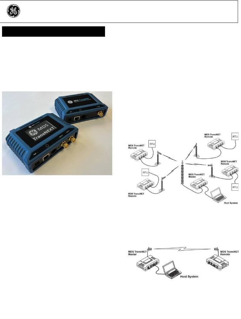
GE MDS TransNEXT User manual

GE
GE MDS Mercury Series User manual

GE
GE GEC-1PVTC-F Assembly instructions

GE
GE MDS SDM9 User manual

GE
GE MDS SD4 Series User guide

GE
GE 3-5875A User manual

GE
GE MDS SDM4-1 User manual

GE
GE CITIZENS BAND TRANSCEIVER 3-5980 User manual