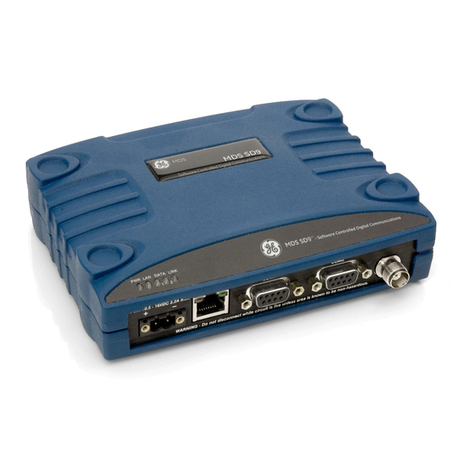
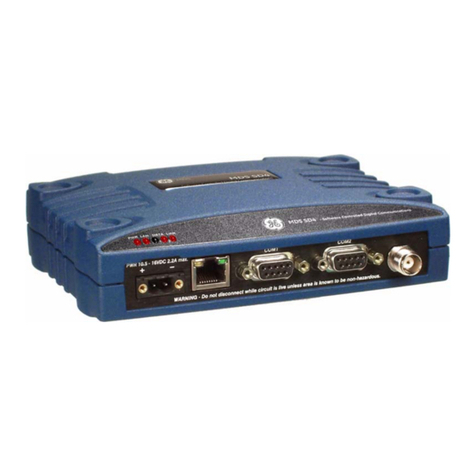
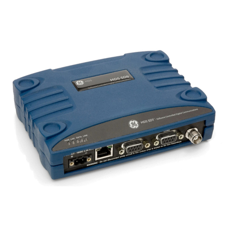
GE MDS SD Series User manual

Installation and Operation Guide
Reference Manual
MDS 05-4846A01, Rev. C
DECEMBER 2009
Covering ES/SS Units Operating in Transparent and Packet Modes
with Firmware Version 3.x
MDS SD Series
Secure, Long Range IP/Ethernet & Serial

Need Quick-Start instructions for this product? Please refer to publication 05-4847A01.
All GE MDS user guides are available online at www.gemds.com

MDS 05-4846A01, Rev. C SD Series Ref. Manual (Packet & Transparent Mode) i
TABLE OF CONTENTS
1.0 INTRODUCTION .................................................................................................................. 1
1.1 Conventions Used in This Manual .................................................................................................1
1.2 Electronic Manuals ........................................................................................................................2
2.0 PRODUCT DESCRIPTION................................................................................................... 3
2.1 Front Panel Connectors and Indicators .........................................................................................3
2.2 Key Product Features ....................................................................................................................4
2.3 Model Offerings .............................................................................................................................4
2.4 Operating Modes and Applicable Manuals ....................................................................................5
2.5 Accessories and Spares ................................................................................................................6
3.0 TYPICAL APPLICATIONS.................................................................................................... 7
3.1 Operating Parameters ...................................................................................................................7
Multiple Address Systems (MAS) .............................................................................................8
Point-to-Point System...............................................................................................................9
IP/Ethernet Polling....................................................................................................................9
IP Polling of Serial Remotes...................................................................................................10
Serial Remotes with Two Serial Ports.....................................................................................10
Port Sharing with Multiple Hosts.............................................................................................11
4.0 INSTALLATION PLANNING ............................................................................................... 12
4.1 Mounting Options ........................................................................................................................13
Optional DIN Rail Mounting ....................................................................................................14
4.2 Antennas and Feedlines ..............................................................................................................14
Antennas.................................................................................................................................14
Feedlines ................................................................................................................................15
4.3 DC Power Connection .................................................................................................................16
4.4 Grounding Considerations ...........................................................................................................16
4.5 Serial Data Interfaces ..................................................................................................................17
COM1 (Management) Connections........................................................................................17
COM2 (Data) Connections......................................................................................................18
4.6 Ethernet Data Interface (RJ-45) ..................................................................................................20
5.0 STEP-BY-STEP INSTALLATION ........................................................................................ 21
5.1 Initial Configuration ......................................................................................................................22
Serial vs. Telnet Access..........................................................................................................22
Connecting a PC & Setting Basic Parameters........................................................................22
5.2 Initial Startup & Checkout ............................................................................................................26
Ethernet Connector LEDs.......................................................................................................26
5.3 Optimizing the Radio Network .....................................................................................................27
Antenna SWR Check..............................................................................................................27

ii SD Series Ref. Manual (Packet & Transparent Mode) MDS 05-4846A01, Rev. C
Inter-Packet Gap Settings.......................................................................................................27
Baud Rate Setting...................................................................................................................27
Modem Type Setting...............................................................................................................27
Ethernet Settings ....................................................................................................................28
6.0 MANAGING THE TRANSCEIVER.....................................................................................29
6.1 Menu Access ...............................................................................................................................29
6.2 Menu Structure ............................................................................................................................30
6.3 Menu Navigation .........................................................................................................................30
6.4 Logging Out of the Menu System ................................................................................................30
6.5 Task-Oriented Menu Chart ..........................................................................................................32
6.6 Using the Menu System—Common Tasks ..................................................................................36
Viewing Status and Performance Information.........................................................................36
6.7 View/Set Radio (RF) Operating Parameters ...............................................................................42
RF Output Power Setting........................................................................................................42
Modem Type Setting...............................................................................................................42
RX and TX Frequencies..........................................................................................................43
Soft-Carrier Dekey Setting......................................................................................................44
RX and TX Time-Out Settings.................................................................................................44
Datakey Setting.......................................................................................................................46
RTSkey Setting.......................................................................................................................46
Push-To-Talk Delay.................................................................................................................46
Clear-to-Send Delay ...............................................................................................................46
Switched Carrier Setting (B Modems Only)............................................................................47
Listen Before Transmit (LBT) Feature.....................................................................................47
View Received Signal Strength (RSSI)...................................................................................49
6.8 View/Set Device Configuration ....................................................................................................50
Viewing Serial Number and Version Information ....................................................................50
Setting Owner Name/Message...............................................................................................51
Enabling/Disabling Sleep Mode..............................................................................................52
Setting Serial COM LED Mode ...............................................................................................53
Viewing/Setting Radio Mode...................................................................................................53
Setting the User Interface Type ..............................................................................................53
Configuring the Radio to Support Multiple Hosts....................................................................54
Configuring Packet Settings....................................................................................................55
Configuring Diagnostic Settings..............................................................................................56
6.9 Security Settings .........................................................................................................................58
Setting a Password.................................................................................................................58
Setting the AES Wireless Security Parameters ......................................................................59
Menu.......................................................................................................................................60
6.10 Ethernet Configuration ..............................................................................................................62
Configuring the IP Settings.....................................................................................................62
Ethernet Bridging....................................................................................................................64
IP Payload Configuration Settings..........................................................................................66
IP Payload Configuration—Menu Selections..........................................................................69
6.11 Serial Configuration ...................................................................................................................71
Configuring COM1 Settings....................................................................................................72
Configuring COM2 Settings....................................................................................................73
6.12 Maintenance & Diagnostic Tests ..............................................................................................75
MDS 05-4846A01, Rev. C SD Series Ref. Manual (Packet & Transparent Mode) iii
Managing Configuration Files.................................................................................................75
Performing Remote Management...........................................................................................78
Performing Radio Tests...........................................................................................................79
Reprogramming the Transceiver.............................................................................................83
Remote Reprogramming.........................................................................................................85
Conducting a PING Test .........................................................................................................86
Conducting a Linktest .............................................................................................................86
Viewing Enabled Features......................................................................................................87
Viewing Active Alarms/Events.................................................................................................88
Configuring the Alarm Signal..................................................................................................88
Viewing I/O Statistics ..............................................................................................................90
7.0 TROUBLESHOOTING........................................................................................................ 92
7.1 LED Indicators .............................................................................................................................94
7.2 Event Codes ................................................................................................................................94
Checking for Alarms................................................................................................................94
Major Alarms vs. Minor Alarms...............................................................................................95
Status and Informational Events .............................................................................................95
Event Code Definitions ...........................................................................................................95
8.0 TECHNICAL REFERENCE ................................................................................................ 97
8.1 Performing Network-Wide Remote Diagnostics ..........................................................................97
8.2 Upgrading the Radio’s Firmware (Local Method) ........................................................................98
Upgrading Firmware via TFTP (LAN port)..............................................................................99
Upgrading Firmware (via Serial Port)....................................................................................103
8.3 Over-the-Air Firmware Upgrades ..............................................................................................103
Intrusive vs. Passive (Non-Intrusive) Mode ..........................................................................103
OTA Reprogramming Overview............................................................................................105
Cancelling OTA Reprogramming ..........................................................................................105
Error Conditions/Recovery....................................................................................................106
Execution and Menu Examples ............................................................................................106
8.4 COM1 Operating Modes ...........................................................................................................108
Options..................................................................................................................................108
Changing COM1 Modes .......................................................................................................108
8.5 Implementing Sleep Mode .........................................................................................................110
8.6 User-Programmable I/O Functions ............................................................................................ 111
8.7 Technical Specifications ............................................................................................................ 111
9.0 GLOSSARY OF TERMS & ABBREVIATIONS ..................................................................113
9.1 dBm-Watts-Volts Conversion Chart ...........................................................................................118
Entering Commands.............................................................................................................120
Detailed Command Descriptions ..........................................................................................122
Copyright and Trademark
This manual and all software described herein is protected by Copyright: 2009 GE MDS, LLC. All
rights reserved. GE MDS, LLC reserves its right to correct any errors and omissions in this publi-
cation. Modbus® is a registered trademark of Schneider Electric Corporation. All other trademarks
and product names are the property of their respective owners.

iv SD Series Ref. Manual (Packet & Transparent Mode) MDS 05-4846A01, Rev. C
RF Safety Notice
Concentrated energy from a directional antenna may pose a health hazard to
humans. Do not allow people to come closer to the antenna than the distances
listed in the table below when the transmitter is operating. More information on
RF exposure can be found online at the following website:
www.fcc.gov/oet/info/documents/bulletins.
FCC Part 15 Notice
Operation is subject to the following two conditions: (1) this device may not cause harmful inter-
ference, and (2) this device must accept any interference received, including interference that may
cause undesired operation. Any unauthorized modification or changes to this device without the
express approval of the manufacturer may void the user’s authority to operate this device. Further-
more, this device is intended to be used only when installed in accordance with the instructions out-
lined in this manual. Failure to comply with these instructions may void the user’s authority to
operate this device.
Manual Revision and Accuracy
This manual was prepared to cover a specific version of firmware code. Accordingly, some screens
and features may differ from the actual unit you are working with. While every reasonable effort
has been made to ensure the accuracy of this publication, product improvements may also result in
minor differences between the manual and the product shipped to you. If you have additional ques-
tions or need an exact specification for a product, please contact GE MDS using the information at
the back of this guide. In addition, manual updates can often be found on our web site at
www.gemds.com.
Environmental Information
The manufacture of this equipment has required the extraction and use of natural resources.
Improper disposal may contaminate the environment and present a health risk due to hazardous
substancescontained within. To avoiddissemination of these substancesinto our environment, and
to limit the demand on natural resources, we encourage you to use the appropriate recycling sys-
temsfor disposal. Thesesystems will reuse or recycle most of the materials found in this equipment
in a sound way. Please contact GE MDS or your supplier for more information on the proper dis-
posal of this equipment.
Antenna Gain vs. Minimum RF Safety Distance
Antenna Gain
0–5 dBi 5–10 dBi 10–16.5 dBi
Safety Distance (SD4) 0.79 meter 1.41 meters 3.05 meters
Safety Distance (SD9) 0.46 meter .82 meters 1.74 meters
Safety Distance (SD2) For SD2, maintain an RF safety distance of
1.50 meters for a 7 dBd (9.15 dBi) antenna.
Use of higher gain antennas means
increasing the distance accordingly.
Safety Distance
(Other SD models): Consult factory prior to operation
RF Exposure

MDS 05-4846A01, Rev. C SD Series Ref. Manual (Packet & Transparent Mode) v
CSA/us Notice
This product is approved for use in Class 1, Division 2, Groups A, B, C & D Hazardous Locations.
Such locations are defined in Article 500 of the National Fire Protection Association (NFPA) pub-
lication NFPA 70, otherwise known as the National Electrical Code. The transceiver has been rec-
ognized for use in these hazardous locations by the Canadian Standards Association (CSA) which
also issues the US mark of approval (CSA/US). The CSA Certification is in accordance with CSA
STD C22.2 No. 213-M1987.
CSA Conditions of Approval: The transceiver is not acceptable as a stand-alone unit for use in the
hazardous locations described above. It must either be mounted within another piece of equipment
which is certified for hazardous locations, or installed within guidelines, or conditions of approval,
as set forth by the approving agencies. These conditions of approval are as follows: The transceiver
must be mounted within a separate enclosure which is suitable for the intended application.The
antenna feedline, DC power cable and interface cable must be routed through conduit in accor-
dance with the National Electrical Code. Installation, operation and maintenance of the transceiver
should be in accordance with the transceiver's installation manual, and the National Electrical
Code. Tampering or replacement with non-factory components may adversely affect the safe use
of the transceiver in hazardous locations, and may void the approval. A power connector with
screw-type retaining screws as supplied by GE MDS must be used.
Do not disconnect equipment unless power has been switched off or the area is known to
be non-hazardous. Refer to Articles 500 through 502 of the National Electrical Code
(NFPA 70) for further information on hazardous locations and approved Division 2 wiring
methods.
Product Test Data Sheets
Test Data Sheets showing the original factory test results for this unit are available upon request
from the GE MDS Quality Leader. Contact the factory using the information at the back of this
manual. Serial numbers must be provided for each product where a Test Data Sheet is required.
EXPLOSION
HAZARD!

vi SD Series Ref. Manual (Packet & Transparent Mode) MDS 05-4846A01, Rev. C

MDS 05-4846A01, Rev. C SD Series Ref. Manual (Packet & Transparent Mode) 1
1.0 INTRODUCTION
This Reference Manual is one of two books provided for users of the
MDS SD Series Transceiver (Figure 1). It contains an overview of
common applications, installation planning data, technical specifica-
tions, troubleshooting, and a listing of software menus. This manual
should be available to technical personnel who perform network design,
configuration, and troubleshooting of the equipment.
A companion Instruction Sheet is also available (Part no. 05-4847A01).
The scope of the Instruction Sheet is limited to installing the transceiver
and placing it in service for the first time.
Invisible place holder
Figure 1. MDS SD Series Transceiver
1.1 Conventions Used in This Manual
Software & Menu
Notations This product is designed for software control via a connected PC. To
show the names of software commands, keyboard entries, or other infor-
mation displayed on a PC screen, a distinctive, bolded font is used as fol-
lows:
Bolded font example (used for software commands and keyboard entries)
To show the navigation path leading to a particular menu, this same font
is used with forward-pointing arrows between menu names. For
example, suppose you wish to access the radio’s Packet Settings Menu.
The navigation string shown would appear as follows:
Main Menu>>Device Configuration>>Packet Settings
NOTE: The menu screens shown in this manual were obtained from a
transceiver operating in a lab environment. They are provided
as examples only. The parameters and settings displayed may
not reflect actual field service conditions.

2 SD Series Ref. Manual (Packet & Transparent Mode) MDS 05-4846A01, Rev. C
Model Number
Notations The term “SD” or “SD Series” is used in this manual to denote all
models in the SD product line. Specific model numbers such as MDS
SD2 (216-235 MHz), MDS SD4 (350-512 MHz), and MDS SD9
(928-960 MHz) are used only when necessary to reference model-spe-
cific features.
Authorization
Features Some features of the radio are dependent on purchased options and
applicable regulatory constraints. A “key” icon is shown near the
headingof any suchfeatures. If yourradio is not currently authorized for
a needed feature, contact your factory representative for information on
obtaining a new authorization code/key.
1.2 Electronic Manuals
All SD Series manuals are available in printed or electronic form. Elec-
tronic manuals may be downloaded from our web site at
www.gemds.com. The website also contains links to Application Bul-
letins and other product information.

MDS 05-4846A01, Rev. C SD Series Ref. Manual (Packet & Transparent Mode) 3
2.0 PRODUCT DESCRIPTION
The SD Transceiver is a software-configurable, industrial radio for use
in licensed poll-response telemetry networks. It may be interfaced with
a variety of data control equipment including remote terminal units
(RTUs), programmable logic controllers (PLCs), flow computers, and
similar devices. Data interface connections may be made for both serial
(RS-232/RS-485) and limited Ethernet protocols. It is designed pri-
marily for use in polled networks where a central station communicates
with each remote, one at a time to convey data and control signals.
The radio employs digital signal processing (DSP) technology and a
fully digital transmit and receive IF chain to provide robust communica-
tionseven underadverse conditions.Digital signal processing alsohelps
eliminate the effects of component variations or temperature swings,
resulting in an optimized communications link at all times.
2.1 Front Panel Connectors and Indicators
Figure 2 shows the transceiver’s front panel connectors and indicators.
These items are referenced in various locations in this manual. The
transceiver’s LED functions are described in Table 10 on Page 26.
Invisible place holder
Figure 2. Front Panel Connectors & Indicators
ANTENNA
CONNECTOR (TNC)
SERIAL DATA
CONNECTORS (DB-9)
DC INPUT
POWER
LED INDICATOR
PANEL
ETHERNET
CONNECTOR (RJ-45)
COM1 used for radio management

4 SD Series Ref. Manual (Packet & Transparent Mode) MDS 05-4846A01, Rev. C
2.2 Key Product Features
The transceiver is designed to meet the demanding needs of today’s
industrial wireless networks in a compact, rugged package. It offers an
array of features in one hardware platform:
• Ethernet & serial interfaces—ideal for migration to IP networks
• Dual serial functionality (RS-232 and RS-485)
• Available encryption of payload data (AES 128-bit)
• Software-configurable via a built-in menu system—no manual
controls or adjustments. Supports Serial or Telnet management.
• Over-the-air reprogramming—no unnecessary trips to radio sites
• Licensed 5-watt design, maximizes communications range with
low interference risk from other users
• Configurable as a Remote or a Master unit
• Low power “sleep mode”—ideal for battery-powered solar sites
• “x710 Mode” for drop-in compatibility with MDS x710 radios
• Listen Before Transmit (LBT) feature for collision avoidance
• Virtual Radio Channels (VRC) support multiple polling applica-
tions on one radio
• Supports a wide variety of modem speeds and bandwidths for reg-
ulatory compliance in virtually all regions of the world
NOTE: Some features may not be available on all units, depending on the
options purchased and regulatory constraints for the region in which
the radio will operate.
2.3 Model Offerings
The radio is available in three model configurations:
•Ethernet—All SD features and functionality
•Standard—All features, except Ethernet functionality
•x710—Direct, drop-in compatibility for networks using a mix of
SD and older MDS x710 radios.
Model Number
Codes The unit’s complete model number is printed on the bottom label. Addi-
tional unit details are available through the Device Information Menu,
described later in this manual.

MDS 05-4846A01, Rev. C SD Series Ref. Manual (Packet & Transparent Mode) 5
2.4 Operating Modes and Applicable Manuals
The transceiver may be configured to operate in any one of three modes:
•Packet Mode—Payload data from the radio’s serial or Ethernet
ports is assembled into packets and transmitted over the air.
Packet mode supports Ethernet Bridging, AES 128-bit encryp-
tion, and multihost operation. This mode is ideal for networks
containing all SD radios. This manual covers Packet Mode
radios.
•Transparent Mode—This mode is over-the-air compatible with
MDS x710 transceivers, while supporting payload data on the
Ethernet interface. This mode is ideal for mixed networks con-
taining SD and MDS x710 radios. It allows currently deployed
x710 networks to add the ability to support Ethernet data. This
manual covers Transparent Mode radios.
•x710 Mode—This mode provides direct, drop-in compatibility
with MDS x710 (4710 or 9710) transceivers, and uses the same
core command set as these radios. It is ideal for use in systems
containing a mix of newer SD radios and legacy MDS x710 units.
This manual does not cover x710 Mode operation. Refer instead
to the following manuals for instructions:
•Start-Up Guide (x710 Mode)— Part No. 05-4669A01
•Reference Manual (x710 Mode)—Part No. 05-4670A01
Invisible place holder
Figure 3. SD Transceivers offer compatibility with older MDS x710
Transceivers (right), and may be used for replacement or
interoperability in these networks. A retrofit kit is available for
connector conversion (see Table 1).

6 SD Series Ref. Manual (Packet & Transparent Mode) MDS 05-4846A01, Rev. C
2.5 Accessories and Spares
Table 1 lists common accessories and spare items for the transceiver.
GE MDS also offers an Accessories Selection Guide listing an array of
additional items that may be used with the product. Contact your factory
representative or visit www.gemds.com to obtain a copy of the guide.
Table 1. Accessories & Spare Items
Accessory Description Part Number
DC Power Plug,
2-pin, polarized Mateswithpowerconnectoronradio
case. Screw terminals provided for
wires, threaded locking screws to
prevent accidental disconnect.
73-1194A53
Retrofit Kit, Digital Contains adapters and connectors
needed to facilitate the replacement
of an existing MDS x710A/C/M
digital transceiver.
03-4696A01
Retrofit Kit, Analog Contains adapters and connectors
needed to facilitate the replacement
of an existing MDS x710A/C/M
analog transceiver.
03-4697A01
Instruction Sheet
(for Packet and
Transparent Modes)
Describes the installation and setup
of the transceiver. A companion to
this Reference Manual.
05-4847A01
Flat Mounting
Brackets
(Standard)
Brackets that attach to the bottom of
the unit. Used for mounting to a flat
mounting service.
03-4123A14
Flat Mounting
Brackets
(x710-compatible)
Brackets that attach to the bottom of
the unit. Used for mounting to a flat
mounting service. Bracket matches
MDS x710 Transceiver mounting
holes.
Consult
Factory
DIN Rail Mounting
Bracket Kit Contains bracket for mounting the
transceiver to standard 35 mm DIN
rails commonly used in equipment
cabinets and panels.
03-4125A04
Reprogramming
Application for
Firmware Upgrade
Automated software program for
upgrading the radio’s internal
firmware code. This application is
under development at press time.
Check with your factory
representative for availability.
06-6241A01

MDS 05-4846A01, Rev. C SD Series Ref. Manual (Packet & Transparent Mode) 7
3.0 TYPICAL APPLICATIONS
This section describes some common scenarios in which the transceiver
may be employed. A number of variations are possible, and if you have
unique requirements not covered here, it is recommended that you con-
sult a support specialist at GE MDS. Contact information is provided at
the back of this manual.
3.1 Operating Parameters
The transceiver is intended for use in poll-response networks where a
central Master unit communicates with a number of Remote radios one
at a time. The Master exchanges data with the currently-connected
Remote, and when finished, it establishes a new connection with the
next Remote in the polling order. Some networks operate with a variant
of this scheme called report-by-exception, whereby a Remote only
transmits if it has traffic to send, typically prompted by a change in
status conditions from the Remote data equipment.
The radio’s menu system includes a number of parameters which may
be set to suit the requirements of a particular application. Table 2 pro-
vides a summary of common applications, protocols, radio modes used,
and the required settings for three key parameters: AES (encryption),
CSMA (collision avoidance/Listen Before Transmit), and Multihost set-
tings. Refer to the table to determine what applications can be supported
and what the required radio settings are.
Table 2. Application Types vs. Key Radio Settings
Application Protocol Radio
Mode AES CSMA (LBT) Multihost Notes
Single Port Serial
Polling without
encryption (COM2
or COM1)
Modbus RTU Transparent OFF OFF OFF
Single Port Serial
Polling with
encryption (COM2
or COM1)
Modbus RTU Packet ON OFF OFF
PolledMultiplePorts
(any combination of
COM1, COM2, and
IP Payload)
DNP3 and
Modbus RTU Packet ON or OFF OFF Optional
(see note) OFF if polling is
synchronized; On
otherwise
Polled IP Payload Modbus RTU via
UDP Packet ON or OFF OFF OFF
Polled Bridged
Ethernet Modbus TCP Packet ON or OFF Listen on RX OFF

8 SD Series Ref. Manual (Packet & Transparent Mode) MDS 05-4846A01, Rev. C
Multiple Address Systems (MAS)
This is a very common application for the transceiver. It consists of a
central master unit and several associated remote units as shown in
Figure 4. An MAS network provides communication between a central
host computer and remote terminal units (RTUs) or other data collection
devices in the field. Often, such a system is used to carry telemetry data
to and from widely separated remote radios.
Typical MAS applications may be for automatic, remote monitoring of
gas wells, water tank levels, electric power distribution systems, and
similar control and measurement functions.
Invisible place holder
Figure 4. Typical MAS Point-to-Multipoint Network
Generic Bridged
EThernet IP
(ICMP/TCP/UDP) Packet ON or OFF Listen on RX OFF
Mixed Serial and
Bridged Ethernet Modbus RTU & IP Packet ON or OFF Listen on RX Optional
(see Notes
column)
ON if messages
are one-to-one;
OFF otherwise.
Collisions
expected.
Report by Exception
(see Notes column) Serial and/or IP
Data Packet ON or OFF Listen on
TX/RX OFF Results will vary;
does not follow
polled model.
Single Poll Multiple
Response Serial and/or IP
Data Packet ON or OFF Listen on RX
(see Notes
column)
OFF Itisrecommended
that responses be
staggered using
the LBT
parameters.
Table 2. Application Types vs. Key Radio Settings (Continued)
Application Protocol Radio
Mode AES CSMA (LBT) Multihost Notes
RTU
MASTER STATION
REMOTE RADIO
REMOTE RADIO
RTU
HOST SYSTEM
OR: SDA-Augmented
Master Station
RTU
REMOTE RADIO
RTU
REMOTE RADIO

MDS 05-4846A01, Rev. C SD Series Ref. Manual (Packet & Transparent Mode) 9
Point-to-Point System
Where permitted, the transceiver may also be used in a point-to-point
arrangement. A point-to-point system consists of just two radios—one
serving as a master and the other as a remote (see Figure 5). It provides
a simplex (or half-duplex) communications link for the transfer of data
between two locations.
Invisible place holder
Figure 5. Typical Point-to-Point Link
IP/Ethernet Polling
Many newer data/control networks employ IP/Ethernet connectivity
throughout the system. The SD transceiver is well suited to provide con-
nectivity between such sites using its RJ-45 modular connector on the
front panel. Figure 6 shows an overview of such a system.
Invisible place holder
Figure 6. IP/Ethernet Polling Example
HOST
COMPUTER
REMOTE RADIO
MASTER RADIO
RTU
To Ethernet Port
REMOTE RADIO
(One of several possible sites)
Ethernet
Ethernet RTU
REMOTE RADIO
(One of several possible sites)
Ethernet RTU
Ethernet Ethernet

10 SD Series Ref. Manual (Packet & Transparent Mode) MDS 05-4846A01, Rev. C
IP Polling of Serial Remotes
The transceiver is ideal for use in systems employing a mix of serial and
Ethernet protocols. While many variations are possible, Figure 7 shows
a typical scenario with an Ethernet host at the Master Unit that is polling
serial-based RTUs at the Remote sites.
In this example, the Host Computer is connected directly to the radio’s
Ethernet port, and the RTUs at the Remote sites are connected to the
transceiver via the radio’s COM2 serial data ports. (COM1 may also be
used for payload data if properly configured via the menu system. See
next application example.)
Invisible place holder
Figure 7. IP Polling of Serial Remotes
Serial Remotes with Two Serial Ports
In some cases, it may be necessary to poll more than one RTU at a
Remote site. Figure 8 shows an example of this type of system. Here,
two RTUs are connected to each Remote transceiver, by using both of
the radio’s serial ports—COM1 and COM2.
By default, the radio’s COM1 port is configured for management func-
tions with a connected PC, but it may be configured for data service
using the COM1 Port Settings Menu. (Main Menu>>Serial Configura-
tion>>COM1 Port Settings) This arrangement allows two telemetry net-
works to share a single radio system.
MASTER RADIO
(TCP Client)
HOST COMPUTER
(TCP Server)
REMOTE RADIO
(One of several possible sites)
MODBUS® SERIAL RTU
To COM2
Serial Port
To Ethernet Port
REMOTE RADIO
(One of several possible sites)
To COM2
Serial Port
Ethernet Data Port Menu
MODBUS RTU
Protocol
MODBUS® SERIAL RTU

MDS 05-4846A01, Rev. C SD Series Ref. Manual (Packet & Transparent Mode) 11
In such a system, each RTU gets every message from the host computer,
and the underlying protocol (e.g., Modbus, DNP, etc.) must sort out
which messages are applicable to a specific RTU.
Figure 8. Serial Remotes with Two Serial Ports
Port Sharing with Multiple Hosts
The transceiver allows for several external data networks to use the
same RF network without confusing the data streams. This is known as
“Multihost” operation, and it requires that the radio be operating in
Packet Mode.
In such a system, multiple host computers at the Master Unit poll their
respective RTUs, which may be alone or co-located at the Remote sites.
Figure 9 shows an example of such a system. In this case, two host com-
puters (Host A and Host B) are connected to the Master Unit via the
applicable data ports.
MASTER RADIO
HOST COMPUTER
(Host A)
To Ethernet Port
REMOTE RADIO
(One of several possible sites)
Key Multihost Settings:
Multihost Delay, No. of Ports, IP Address,
Port No., Multihost Time-Out
TCP Ethernet
Ethernet Data Port Menu
REMOTE RADIO
(One of several possible sites)
SERIAL RTU
SERIAL RTU
SERIAL RTU
SERIAL RTU

12 SD Series Ref. Manual (Packet & Transparent Mode) MDS 05-4846A01, Rev. C
At the Remote sites, serial and Ethernet-based RTUs are employed, and
responding to a specific host computer. In the case of the Remote shown
on the lower right side of the drawing, two RTUs are co-located, but
responding to different host computers and handling entirely different
streams of data. Multihost systems eliminate the need for two trans-
ceivers to support separate data collection/control networks.
Figure 9. Multihost System
4.0 INSTALLATION PLANNING
Careful planning of the installation site will help achieve optimal performance
from the transceiver. This section discusses the factors that should be consid-
ered prior to installing the radio. Step-by-step installation procedures begin on
Page 21.
Figure 10 shows a typical remote station arrangement. The specific details at
an installation site may vary, but there are three main requirements for
installing the transceiver in all cases:
• Adequate and stable primary power
• An efficient and properly installed antenna system
• Correct interface connections between the transceiver and the data
device.
MASTER RADIO
(Multihost Enabled)
HOST COMPUTER
(Host A)
To Ethernet Port
REMOTE RADIO
(One of several possible sites)
Key Multihost Settings:
Multihost Delay, No. of Ports, IP Address,
Port No., Multihost Time-Out
TCP Ethernet
HOST C
HOST COMPUTER
(Host B)
Ethernet Data Port Menu
Serial
To COM2
Serial Port
Ethernet RTU Responding to
Host A
Serial RTU Responding to
Host B
UDP Ethernet
REMOTE RADIO
(One of several possible sites)
Serial RTU Responding to
Host B
Co-located RTUs
Responding to
Different Hosts
Other manuals for MDS SD Series
5
Table of contents
Other GE Transceiver manuals

GE
GE MDS SD 1 User manual

GE
GE MDS Mercury Series User manual

GE
GE MDS iNET Series User manual

GE
GE MDS 9710T User manual

GE
GE MDS entraNET Series User guide

GE
GE MDS SD Series User manual

GE
GE CITIZENS BAND TRANSCEIVER 3-5980 User manual

GE
GE VIC5211M Installation guide

GE
GE 900 MHz User manual

GE
GE MDS SD4 Series User guide

GE
GE MDS Mercury Series User manual

GE
GE Reason RT412 User manual

GE
GE MDS Mercury Series User manual

GE
GE MDS SD4A User manual

GE
GE MDS iNET 900 User manual

GE
GE MDS SD Series User manual

GE
GE A3-5825B User manual

GE
GE 3-5875A User manual

GE
GE GEC-1PVTC-F Assembly instructions

GE
GE MDS NETio-TB Series Original operating instructions