Yaesu FTDX101D User manual

Operation Manual

Table of Contents
Accessories & options ................................. 1
Supplied Accessories ......................................1
Available options .............................................1
Installation and interconnections ................. 2
Antenna Considerations ..................................2
Connection of Antenna and Power Cables......2
Connection of Microphone, Headphone,
Key, Keyer and FH-2 .......................................3
Front panel controls & Switches.................. 4
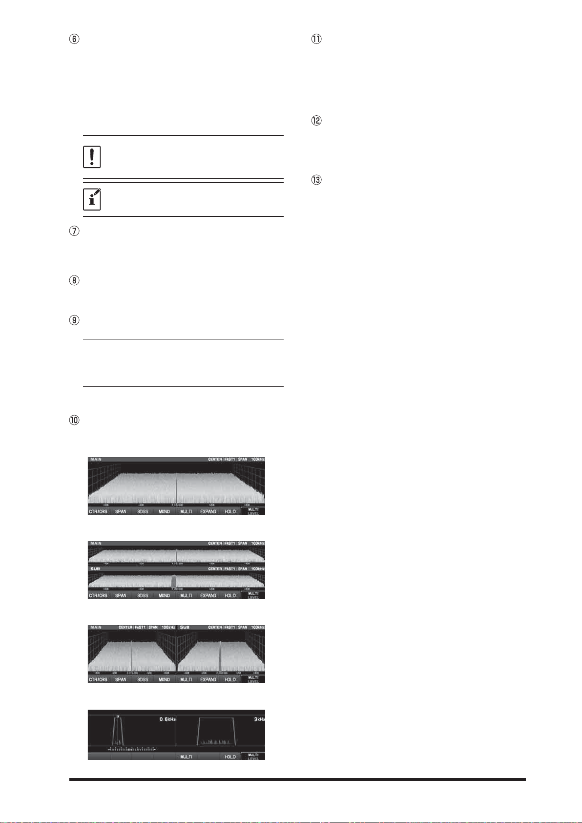
Display indications..................................... 13
Meter display .................................................15
Rear Panel................................................. 16
Basic Operation......................................... 18
Turning the Transceiver ON and OFF ...........18
Adjusting the Audio Volume Level .................18
Switch between MAIN and SUB....................18
Operating Band Selection .............................19
Operating Mode Select..................................19
Setting the Operating Frequency ..................20
RF Power output control................................21
Antenna selection..........................................21
MIC Gain Adjustment ....................................21
DIAL knob Lock .............................................21
Receiver Accessories ................................ 22
&/$5&ODUL¿HU2SHUDWLRQ ............................22
RF Gain .........................................................22
AGC (
Automatic Gain Control
........................22
Band Stack Operation ...................................23
CW Decode ...................................................23
Audio Peak Filter ...........................................23
&:6SRWWLQJ=HUR%HDWLQJ ..........................24
CW Pitch Adjustment.....................................24
Interference Rejection ............................... 25
,32,QWHUFHSW3RLQW2SWLPL]DWLRQ.................25
VC Tune Filter ...............................................25
Contour Control Operation ............................26
IF SHIFT Operation .......................................26
WIDTH Tuning...............................................27
:1:LGH1DUURZ .......................................27
$77$WWHQXDWRU ............................................27
IF NOTCH Filter Operation............................27
DNR Operation..............................................28
DNF Operation ..............................................28
1RLVH%ODQNHU1%2SHUDWLRQ.......................28
Transmitter Operation................................ 29
Transmission .................................................29
Changing the transmission meter..................29
7277LPH2XW7LPHU ...................................29
Speech Processor .........................................30
Monitor ..........................................................30
VOX...............................................................30
Split-Frequency Operation ............................31
CW Mode Operation.................................. 32
Setup for Straight Key Operation ..................32
Using the Built-in Electronic Keyer ................33
FM Mode Operation................................... 34
Repeater Operation.......................................34
Tone Squelch Operation................................34
SCOPE...................................................... 35
Scope function setting ...................................36
Memory Operation..................................... 38
Memory Storage............................................38
Memory Channel Recall ................................38
Erasing Memory Channel Date .....................39
40%4XLFN0HPRU\%DQN ..........................39
Setting Menu ............................................. 40
Using Menu ...................................................40
Resetting the Microprocessor.................... 45
6SHFL¿FDWLRQ .............................................. 46
General..........................................................46
Transmitter ....................................................46
Receiver ........................................................47

1
Accessories & options
Supplied Accessories
SSM-75G
DC Power Cord
6SDUH)XVH$
Operation Manual
Available options
+DQG0LFURSKRQH 660*HTXLYDOHQWWRWKHVXSSOLHGPLFURSKRQH
Reference Microphone M-1
Dual Element Microphone M-100
Ultra-High-Fidelity Desktop Microphone MD-200A8X
Desktop Microphone MD-100A8X
Lightweight Stereo Headphone YH-77STA
External Automatic Antenna Tuner FC-40
Remote Control Keypad FH-2
/LQHDU$PSOL¿HU$&3RZHU6XSSO\ 9/93
9//LQHDU$PSOL¿HU&RQQHFWLRQ&DEOH &7

2
Installation and interconnections
Antenna Considerations
The FTDX101D is designed for 50 Ohm resistive impedance at the amateur operating frequencies.
6HOHFWWKHSURSHUDQWHQQDGLSROHDQWHQQD<$*,DQWHQQDFXELFDOTXDGDQWHQQDHWFVXLWDEOHIRUWKH
chosen operation and bands.
Construct the antenna and coaxial cable, or use a suitable antenna tuner, to maintain the impedance pre-
sented to the FTDX101D antenna connector for an SWR of 1.5 or less. Careful preparation of the antenna
and/or tuner will permit maximum performance and protect the transceiver from damage.
High voltages may be present on the antenna; install it so it will not be easily touched when in operation.
Connection of Antenna and Power Cables
Please follow the outline in the illustration regarding the proper connection of antenna coaxial cables, as
well as the DC power cable.
ANT 1 ANT 2 EXT SPKR KEY
ACC TUNER
PTT
METER
RX OUT BRX OUT A IF OUT A IF OUT B
GND
DC IN
LINEAR +13.8V
REM EXT ALC RS-232C
AB
RED
FUSE: 25A
DC power cord (supplied)
BLACK
To prevent damage from lightning, atmospheric electricity,
electrical shock etc., please provide a good earth ground.
Use a short, thick, braided cable to connect your station equipment
to the buried ground rod (or alternative earth ground system).

3
Connection of Microphone, Headphone, Key, Keyer and FH-2
ANT 1 ANT 2 EXT SPKR KEY
ACC TUNER
PTT
METER
RX OUT BRX OUT A IF OUT A IF OUT B
GND
DC IN
LINEAR +13.8V
REM EXT ALC RS-232C
AB
UP
+5V
DOWN FAST GND
PTT
MICGND
MIC
ijPP
5HPRWH&RQWURO.H\SDG
FH-2

4
Front panel controls & Switches
ON/OFF Switch
Press and hold in this switch for one second to turn
the transceiver on. Similarly, press and hold in this
switch for one second to turn the transceiver off.
USB Jack
Connect a USB A type keyboard or mouse.
KEY
Connect a telegraph key or electronic keyer paddle
to use for CW mode operation.
When connecting a key or other device to
the KEY jack, use only a 3-contact (“ste-
UHR´ PPSKRQHSOXJDFRQWDFWSOXJ
will place a short between the ring and the
JURXQGHGVKDIW RIWKHSOXJUHVXOWLQJLQD
constant “key-down” condition.
DOT DASH COMMON
DOT DASH COMMON
KEY
KEY
NC GND
GND
PHONES Jack
&RQQHFWKHDGSKRQHV WRWKLVࢥVWDQGDUGVWHUHR
jack.
When wearing headphones, we recommend
that you turn the AF Gain levels down to
their lowest settings before turning power
on, to minimize the impact on your hearing
caused by audio “pops” during switch-on.
SIGNAL GND
MIC
This 8-pin jack accepts input from a microphone
uti-lizing a traditional YAESU HF transceiver pinout.
UP
+5V
DOWN FAST GND
PTT
MICGND
MIC

5
TUNE
This is the on/off switch for the FTDX101D Auto-
matic Antenna Tuner.
3UHVVWKH>781(@NH\EULHÀ\WRDFWLYDWHWKHDQWHQQD
WXQHU3UHVVWKH>781(@NH\EULHÀ\DJDLQWRGLVDEOH
the antenna tuner.
Press the [TUNE] key for about 1 second to start
“automatic tuning”.
Since the transceiver transmits automati-
cally during automatic tuning, make sure to
connect an antenna or dummy load before
tuning up.
When the antenna or dummy load does not
match the impedance, “HI-SWR” will appear
on the touch panel.
VOX
This key enables automatic voice-actuated trans-
mitter switching. While VOX is activated, the LED
inside this key glows orange.
MOX
3UHVVLQJWKLV NH\HQJDJHVWKH3773XVKWR7DON
circuit to activate the transmitter.
ZIN/SPOT
ZIN
Touch [ZIN/SPOT] to cause the receiving frequency
to zero-in automatically while receiving the CW sig-
nal.
SPOT
Pressing and holding [ZIN/SPOT], the tone is out-
put from the speaker.
DISP
Each time the key is pressed, the display of the
scope screen changes as shown below.
Only “MAIN” or “SUB” will be displayed
¯
Upper side: MAIN, Lower side: SUB
¯
Left side: MAIN, Right side: SUB
¯
Left side: MAIN, Right side: SUB
S.MENU
Settings related to scope display.
SPEED: Setting scope sweep speed.
PEAK: Adjust the peak signal color density.
MARKER: Marker display ON or OFF.
COLOR: Changing scope display color.
LEVEL: Adjust the reference level.
FUNC
3UHVVWKH NH\EULHÀ\WRGLVSOD\WKHIXQFWLRQPHQX
screen where the operation settings for a variety of
IXQFWLRQVPD\ EHFRQ¿JXUHG3UHVVWKLVNH\DJDLQ
to close the function menu screen.
SD memory card slot
You can use the commercially available SD memo-
ry card to save various settings, save the memory
FRQWHQWVDQGXSGDWHWKH¿UPZDUH

6
MODE
6ZLWFKWKHUDGLRPRGXODWLRQIRUPRSHUDWLQJPRGH
Press and hold this key to display the radio modu-
lation form selection screen, then touch and select
your desired modulation form.
SSB
The operation mode becomes “SSB”.
Press the [SSB] key will toggle to the alternate
mode. For example, In the LSB or USB modes,
press the [MODE] key toggles between “LSB” and
“USB” mode.
CW
The operation mode becomes “CW”.
Press the [CW] key will toggle to the alternate
mode. For example, In the CW-L or CW-U modes,
press the [MODE] key toggles between “CW-L” and
“CW-U” mode.
BK-IN
This key turns the CW break-in capability on and
off. While CW break-in is activated, the LED inside
this key glows orange.
MONI
This key enables the transmit monitor in SSB, CW
and AM modes. While activated, the LED inside this
key glows orange.
SYNC
Change the frequency of the MAIN band with the
MAIN dial, the frequency of the SUB band also
changes in the same step.
SPLIT
Press this key to operate split frequency between
0$,1EDQG XVHGIRUUHFHSWLRQDQG68%EDQG
XVHGIRU WUDQVPLVVLRQ3UHVVDQGKROGLQWKH
[SPLIT] key for one second, the “Quick Split” fea-
ture will be engaged. SUB band transmit will auto-
matically be set to a frequency 5 kHz higher than
the MAIN band receive frequency, with the same
operating mode. The transceiver will operate in the
Split mode.
RX (CLAR)
3UHVVLQJWKLVNH\DFWLYDWHVWKH5;&ODUL¿H7KLVZLOO
allow you to temporarily adjust the receive frequen-
cy up to ±9.990 kHz with the MPVD knob. Press
this key once more to return the receiver to the
RULJLQDOIUHTXHQF\WKH&ODUL¿HURIIVHWZLOOEHUHPHP-
bered, in case you want to use it again.
7RFDQFHOWKH&ODUL¿HURIIVHWSUHVVDQGKROG
the [RX], [TX] or [CLAR] key.
TX (CLAR)
Pressing this key activates the TX Clarifie. This
will allow you to temporarily adjust the transmit fre-
quency up to ±9.990 kHz with the MPVD knob.
7RFDQFHOWKH&ODUL¿HURIIVHWSUHVVDQGKROG
the [RX], [TX] or [CLAR] key.
MAIN
Change the operation band to the MAIN band.
SUB
Change the operation band to the SUB band.

7
SUB AF
The inner [MAIN AF] knob sets the audio level of
the SUB band receiver.
MULTI
This knob incorporates multiple tasks and makes it
very convenient to operate the various functions of
the FTDX101D.
You can assign the desired action from the bellow.
SPEED: Setting scope sweep speed.
PEAK: A
djust the peak signal color density.
MARKER: Marker display ON or OFF.
COLOR: Changing scope display color.
LEVEL: Adjust the reference level.
RF POWER: Output power setting.
MONI LEVEL: Monitor level adjustment.
DNR LEVEL: DNR level adjustment.
NB LEVEL: NB level adjustment.
VOX GAIN: VOX gain adjustment.
VOX DELAY: VOX delay adjustment.
ANTI VOX: ANTI VOX adjustment.
CH DIAL: Frequency change at a predeter-
mined frequency step.
MEM CH: Selects the Desired memory chan-
nel.
GROUP: Selects the memory group.
IF FILTER: 3DVVEDQGZLGWKVHOHFWLRQ RI,)¿O-
ter.
FAST
Pressing this key will change the tuning of the
MAIN Dial knob to a higher step rate.
MAIN AF
The inner [MAIN AF] knob sets the audio level of
the MAIN band receiver.
RF/SQL (MAIN band)
RF
The outer [RF/SQL] knob is the receiver RF gain
control of the MAIN band receiver, which adjusts
WKHJDLQRIWKHUHFHLYHU5)DQG,)DPSOL¿HUVWDJHV
This control is normally left in the fully clockwise
position.
SQL
This knob sets the signal level threshold of the
MAIN band receiver, below which the receiver au-
dio is muted, in FM mode. It is very useful during
local ragchews, to eliminate noise between incom-
ing transmissions. This control is normally kept fully
FRXQWHUFORFNZLVHRIIH[FHSWZKHQVFDQQLQJDQG
during FM operation.
LOCK
This key toggles locking on/off for the MAIN Dial
knob. With “Lock” on, the MAIN Dial knob can still
be turned, but the frequency will not change, and
the “LOCK” appears in the frequency display.
RF/SQL (SUB band)
RF
The outer [RF/SQL] knob is the receiver RF gain
control of the SUB band receiver, which adjusts
WKHJDLQRIWKHUHFHLYHU5)DQG,)DPSOL¿HUVWDJHV
This control is normally left in the fully clockwise
position.
SQL
This knob sets the signal level threshold of the SUB
band receiver, below which the receiver audio is
muted, in FM mode. It is very useful during local
ragchews, to eliminate noise between incoming
transmissions. This control is normally kept fully
FRXQWHUFORFNZLVHRIIH[FHSWZKHQVFDQQLQJDQG
during FM operation.

8
CLAR
When pressed,
MPVD dial will operate as CLAR
dial.
RX (MAIN band)
Press this key to activate receive on the MAIN band
frequency. The LED inside the key will glow green
when the transceiver is receiving on the MAIN band
frequency.
TX (MAIN band)
When this key is pushed, the LED inside the key
will glow red; and, when the PTT switch is pressed,
the transceiver will transmit on the MAIN band fre-
quency.
MAIN
X
W
SUB
Pressing this key momentarily, exchanges the fre-
quency data, of MAIN band and SUB band.
TX (SUB band)
When this key is pushed, the LED inside the key
will glow red; and, when the PTT switch is pressed,
the transceiver will transmit on the SUB band fre-
quency.
RX (SUB band)
Press this key to activate receive on the SUB band
frequency. The LED inside the key will glow green
when the transceiver is receiving on the SUB band
frequency.
VC TUNE
When pressed,
MPVD dial will operate as VC
TUNE dial.
VC TUNE
:KHQSUHVVHGWKH³9&781(´¿OWHUZLOODFWLYDWH
QMB
Pressing the [QMB] key copies the contents (fre-
quency, mode, bandwidth, FM repeater offset, and
&7&66VHWWLQJVLQWRFRQVHFXWLYH40%0HPRULHV
FINE TUNING
When pressed, MAIN dial will operate as FINE
TUNING dial which changes the frequency at 1 Hz
VWHS+]VWHSVLQ$0)0'$7$)0PRGH
MAIN dial
This large knob adjusts the operating frequency.
Clockwise rotation of this knob increases the fre-
quency. Default tuning increments are 10 Hz (CW,
66%577<'$7$/DQG'$7$8+]$0
)0'$7$)0:KHQWKH >)$67@NH\LVSUHVVHG
the tuning steps increases. The available steps are:
Operating Mode 1 Step 1 Dial Rotation
LSB, USB, CW
DATA-L, DATA-U
RTTY
10Hz [100Hz] 10kHz [100kHz]
AM, FM, DATA FM 100Hz [1kHz] 100kHz [1MHz]
[ ]:When [FAST] key is On.
MPVD dial
(MULTI PURPOSE VFO OUTER DIAL)
0$,168%GLDO 9&781(&/$5 &ODULILHU)LUH
DQG&6&XVWRPHU6HOHFWLRQFDQEHVHOHFWHGZLWK
one touch operation.
MAIN/SUB
When pressed, the
MPVD dial operates as the
dial to set the frequency of the SUB band when the
operation band is MAIN band, and the frequency
of the MAIN band when the operation band is SUB
band.

9
C.S
When pressed, the operation of the
MPVD dial
operates with the function assigned in advance (see
EHORZ
RF POWER: Adjusts transmission output.
MONI LEVEL: Adjusts the Monitor level.
DNR LEVEL: DNR level adjustment.
NB LEVEL: NB level adjustment.
VOX GAIN: VOX gain adjustment.
VOX DELAY: VOX delay adjustment.
ANTI VOX: ANTI VOX adjustment.
CH DIAL: Frequency change at a predeter-
mined frequency step.
MEM CH: Selects the Desired memory chan-
nel.
GROUP: Selects the memory group.
IF FILTER: Pass band width selection of IF
¿OWHU
7KHVHWWLQJ PHWKRGLVVHWZLWK>)81&@ĺ
>23(5$7,216(77,1*@ĺ>*(1(5$/@ĺ
[CS DIAL].

10
BAND
These keys allow one-touch selection of the de-
VLUHG$PDWHXUEDQGa0+]7KHNH\VPD\
also be used for direct entry of a desired operating
frequency during VFO operation.
Select the operation band. The band selected in the
MAIN band is white, and the band selected by the
SUB band is illuminated with the blue LED. When
sending, the sending side LED lights in red. Also,
when you press and hold it, the orange LED lights,
so you can use it instead of memo to display the
band to which the antenna is connected.
V/M
This key toggles frequency control between VFO
and the memory system.
M
X
V
Press and hold the [M
X
V] key in for one second
copies the data from the selected memory to VFO,
and two beeps sound. Previous data in VFO will be
over-written.
V
X
M
Save data such as frequency set with VFO to the
memory channel. Press and hold the [V
X
0@NH\ĺ
URWDWHWKH >08/7,@NH\WRVHOHFWFKDQQHOĺSUHVV
the [V
X
0@NH\ĺSUHVVWKH>90@NH\WKHGDWDZLOO
be written to the memory channel.
MIC/SPEED
MIC (SSB and AM mode)
This knob adjusts the microphone input level for
QRQSURFHVVHG66%DQG$0WUDQVPLVVLRQ
The display will show the relative micro-
phone gain level for 1/2 second whenever
this knob is turned.
SPEED (CW mode)
This knob adjusts the keying speed of the inter-
QDO&: NH\HUa:30&ORFNZLVHURWDWLRQ
in-creases the sending speed.
The display will show the keying speed for
1/2 second whenever this knob is turned.
PROC/PITCH
PROC (SSB and AM mode)
7KLVNQRE DGMXVWVWKHFRPSUHVVLRQLQSXWOHYHORI
the transmitter RF speech processor in SSB and
AM mode.
The compression level setting will be shown
for 1/2 second in the display when ever the
outer [PROC/PITCH] knob is turned.
PITCH (CW mode)
The outer [PROC/PITCH] knob selects your pre-
ferred CW tone pitch (from 300 ~ 1050 Hz, in 10 Hz
LQFUHPHQWV
The Spot tone frequency will be shown for
1/2 second in the display when ever the out-
er [PROC/PITCH] knob is turned.

11
NB (MAIN band)
This switch engages the MAIN band IF Noise
Blanker. When the Noise Blanker is activated, the
LED inside the key will glow orange.
The noise blanker level can be adjusted by
turning the [MULTI] knob after pressing and
holding the [NB] key.
DNR (MAIN band)
This key turns the MAIN band Digital Noise Re-
duction circuit on and off. When the Digital Noise
Reduction is activated, the LED inside the key will
glow orange.
The noise reduction level can be adjusted
by turning the [MULTI] knob after pressing
and holding the [DNR] key.
W/N (SUB band)
Touch the [W/N] key to enable one-touch,
mode-specific, selection of a narrow IF DSP filter
setting that does not require resetting the band-
width control to the WIDTH/SHIFT system.
NOTCH (SUB band)
Pressing this key allows you to adjust the center
IUHTXHQF\RIWKH,)1RWFK¿OWHUXVLQJWKH>127&+@
knob. While activated, the LED inside this key
glows orange.
CONT (SUB band)
Pressing this key allows you to select the DSP Con-
tour filter response using the [CONT/APF] knob.
While activated, the LED inside this key glows or-
ange.
APF (SUB band)
In the CW mode, pressing this key will activate
WKH$3)$XGLR 3HDN)LOWHUZKLFKSURYLGHVDYHU\
narrow audio bandwidth. While activated, the LED
inside this key glows orange.

12
SHIFT (SUB band)
Rotate the inner [SHIFT] knob to move the pass-
EDQGRIWKH,)'63¿OWHUE\+]VWHSV7KHWRWDO
adjustment range is ±1.2 kHz. The position of the
passband can be observed on the display. Further-
more, the display will show the shift value of the IF
SHIFT for 1/2 second whenever the [SHIFT] knob
is turned.
WIDTH (SUB band)
Rotate the outer [WIDTH] knob to set the overall band-
ZLGWKRIWKH,)'63¿OWHU&RXQWHUFORFNZLVHURWDWLRQUH-
duces the bandwidth, while clockwise rotation increases
the bandwidth. The current band-width can be observed
on the display. Furthermore, the frequency display will
show the bandwidth of the IF passband for 1/2 second
whenever the [WIDTH] knob is turned.
NOTCH (SUB band)
Press the [NOTCH] switch to turn the IF NOTCH
¿OWHURQRURII5RWDWHWKHLQQHU>127&+@NQREWRDG-
MXVWWKHFHQWHUIUHTXHQF\RIWKH,)127&+¿OWH7KH
QXOOSRVLWLRQRIWKH,)127&+¿OWHUFDQEHREVHUYHG
on the display. Furthermore, the display will show
WKHFHQWHUIUHTXHQF\RIWKH,)127&+¿OWHUIRU
second whenever the [NOTCH] knob is turned.
CONT/APF (SUB band)
CONT
Press the [CONT] switch then turn the outer [CONT/
APF] knob to select the desired CONTOUR filter
UHVSRQVH7KH&217285¿OWHULVHQJDJHGYLDWKH
[CONT] switch.
APF
In the CW mode, press the [APF] switch and then
turn the outer [CONT/APF] knob to select the de-
VLUHG$3)$XGLR3HDN)LOWHUUHVSRQVH7KH$3)LV
engaged via the [APF] switch.
For the MAIN band, the same functions as to
operate.

13
Display indications
Meter (MAIN band)
There are four functions on the main multi-meter.
The bottom three selections in the list below are
transmit functions.
S: Indicates the received signal strength on
the MAIN band, from S-0 to S9+60 dB.
PO: Indicates the RF Power Output, from 0 to
150 Watts on transmit.
COMP: Indicates the compression level of the
speech processor, from 0 to 20 dB.
TEMP: Indicates the final transistor temperature,
from 0 °C to 100 °C.
Frequency Display
Left side: MAIN band frequency display.
Right side: SUB band frequency display.
Filter Display
This indicator is used for viewing the status of the
'63&217285127&+:,'7+DQG6+,)7
Meter (SUB band)
7KHUHDUH¿YHIXQFWLRQVRQWKHVXEPXOWLPHWHU7KH
bottom four selections in the list below are transmit
functions.
S: Indicates the received signal strength on
the SUB band, from S-0 to S9+60 dB.
ALC: Indicates the relative ALC voltage.
VDD ,QGLFDWHVWKH¿QDODPSOL¿HUGUDLQYROWDJH
ID ,QGLFDWHVWKH¿QDODPSOL¿HUGUDLQFXUUHQW
SWR: Indicates the antenna system observed-
VWDQGLQJZDYHUDWLR6:5IURPWR
Operation status display
BUSY: Receiving signal
TX: Transmitting
+: Plus shift
-: Minus shift
ENC: The tone encoder is in use
TSQ: During tone squelch operation
SPLIT: Running split operation
SYNC: During synchro operation
CLAR TRX 75;FODUL¿HU
CLAR TX 7;FODUL¿HU
CLAR RX 5;FODUL¿HU
+xxxHz/-xxxHz&ODUL¿HURIIVHWYDOXHIUHTXHQF\
VFO mode/MEMORY mode
VFO: Displayed in VFO mode.
M-xx: Displays the selected channel number when
in memory mode.
Mode (radio modulation form)
Receive operation status indication
Displays the operation status of each reception
function.
You can change the setting by touching.
ANT: Indicates which antenna is selected by
[ANT] on the display.
IPO: Indicates which front end RF amplifier is
selected [IPO] on the display.
ATT: Indicates the attenuation level, selected
[ATT] on the display.
AGC: Indicates the AGC decay time setting,
which is selected [AGC] on the display.
DNF: Indicates the Digital Notch Filter is ON/OFF.

14
Scope Screen information display
MAIN: MAIN band SCOPE Screen.
SUB: SUB band SCOPE Screen.
HOLD: The operation of the scope screen
DQG¿OWHUIXQFWLRQGLVSOD\LVWHPSRUDUL-
ly stopped.
CENTER: Frequency is constantly in the center
of the screen (for monitoring condi-
tions on both sides of your operating
IUHTXHQF\
CURSOR: The position of the marker moves in
conjunction with the dial knob, and
when the marker exceeds the upper
or lower limit frequency, the screen
scrolls.
FAST1-3 6ZHHSVSHHG)$67WR)$67
SLOW1-2 6ZHHSVSHHG6ORZWR6/2:
SPAN xxxkHz
Scope Screen frequency span (display
UDQJH
Scope Screen
Display spectrum and waterfall useful for monitor-
ing situations in the band. In addition to instanta-
neously switching the display between the MAIN
and SUB bands, dual display is possible to display
the status of both the MAIN and SUB bands.
Scope display setting
CTS/CRS: Switch between the center mode and
the cursor mode of the scope display
method.
SPAN: Sets the width of the scope display.
3DSS: Switch waterfall display from conven-
tional type and 3DSS type.
SINGLE: Information on the SUB band is not
displayed and only information on the
MAIN band is displayed.
MULTI: In addition to the scope display, the
oscilloscope and the AF-FFT are also
displayed.
EXPAND: Expand the display area of the scope
screen in the vertical direction.
HOLD: Temporarily stop the scope display and
¿OWHUIXQFWLRQGLVSOD\RSHUDWLRQ

15
Meter display
S-Meter
(MAIN band)
Name of the meter that operates during transmission
S-Meter
(SUB band)
RF power Output Relative ALC voltage Final amplfier drain voltage
Speech compressor level Final amplfier drain current
Standing Wave Ratio
Final transistor
temperature
Select meter at transmission
The lower part of the S meter is a meter that operates at the time of transmission.
When you touch the meter section, the meter selection screen will be displayed, so select the meter you
ZDQWGHIDXOWVHWWLQJLV³32´RQWKHOHIWVLGH³$/&´RQWKHULJKWVLGH
PO
PO
PO COMP
ALC
ALC
ALC
TEMP ID
VDD
SWR
LEFT METER RIGHT METER
Speech compressor level
RF power Output
Final transistor
temperature Standing Wave Ratio
Final amplfier drain voltage
Final amplfier drain current
Relative ALC voltage
Instructions of each meter are not actual values, but they are indicated by “relative value” which shows a
guide.

16
Rear Panel
Cooling FAN
ANT 1, 2, 3/RX
&RQQHFW\RXU PDLQDQWHQQDVKHUHXVLQJW\SH0
3/FRQQHFWRUV DQGFRD[LDOIHHGOLQHV7KH
LQWHUQDODQWHQQD WXQHUDIIHFWVRQO\WKHDQWHQQDV
connected here, and only during transmission.
EXT SPKR
This 3.5-mm, 2-contact, jack provides variable au-
dio output for an external loudspeaker. The audio
output impedance at this jack is 4 - 8 Ohms, and
the level varies according to the setting of the front
panel [AF] knob.
Inserting a plug into this jack disables the
internal loudspeaker.
SIGNAL GND
KEY
This 1/4-inch 3-contact jack accepts a CW key or
keyer paddle. A two-contact plug cannot be used
in this jack. Key-up voltage is +3.3 V DC, and key-
down cur-rent is 0.3 mA.
KEY
KEY
NC GND
GND
DOT DASH COMMON
DOT DASH COMMON
AF-OUT
This 3.5-mm, 3-contact jack provides dual-channel
low-level receiver output, for recording or external
DPSOL¿FDWLRQ
The front panel [AF] knobs do not affect the
signals at this jack.
SIGNAL(MAIN)
SIGNAL(SUB)
GND
REM
By plugging the FH-2 Remote Control Keypad into
this jack, direct access to the FTDX101D CPU is
provided for control functions such as contest mem-
ory keying, plus frequency and function control.
RTTY/DATA
This 6-pin input/output jack accepts AFSK input
IURPD7HUPLQDO1RGH&RQWUROOHU71&LWDOVRSUR-
vides fixed level receiver audio output, and FSK
keying line.
DATAIN
PTTSHIFT
GND
DATAOUTSQL
METER
This 3.5-mm jack to connect an external meter.
EXT ALC
This RCA input jack accepts negative-going exter-
QDO$/&$XWRPDWLF/HYHO&RQWUROYROWDJHIURPD
linear amplifier to prevent over-excitation by the
transceiver.
METER EXT ALC RS-232CKEY
ACC TUNER
PTT
LINEAR +13.8V
REM
EXT SPKR
AB
ANT 1 ANT 2
RX OUT A IF OUT AGND
DC IN
RX OUT B IF OUT B

17
USB
Connecting to a computer from this jack using a
commercially available USB cable allows remote
control by CAT commands from the computer.
RS-232C
This 9-pin serial DB-9 jack allows external comput-
er control of the FTDX101D. Connect a serial cable
here and to the RS-232C COM port on your per-
VRQDOFRPSXWHUQRH[WHUQDOLQWHUIDFHLVUHTXLUHG
N/A GND
N/A
SERIALOUT
SERIALIN
N/A
RTS CTS
NC
GND
Use this terminal to connect the transceiver to a
good earth ground, for safety and optimum perfor-
mance. Use a large diameter, short braided cable
for making ground connections.
DC IN
This is the DC power supply connection for the
transceiver. Use the supplied DC cable to connect
directly to a DC power supply, which must be capa-
ble of supplying at least 23 A @13.8 VDC.
RX OUT A
This RCA jack provides output of the receiver signal
lines from the Antenna jacks which are connected
to “RX” side of the transceiver’s main T/R switching
circuitry.
LINEAR
This 15-pin output jack provides band selection
data, which may be used for control of optional ac-
cessories such as the VL-1000 Solid-state Linear
$PSOL¿HU
ACC
This 13-pin jack for connecting optional accesso-
ries.
IF OUT A
This RCA jack output the IF signal of the MAIN band re-
ceived signal. This signal does not pass through the roof-
LQJ¿OWHU
TX-GND
This RCA jack’s center pin is closed to ground while
the transceiver’s transmitter is engaged. The tran-
sistor open collector circuit used for this jack is ca-
pable of switching a DC voltage of 60 V at 200 mA,
or DC 30 V at up to 1Amp.
PTT
This RCA input jack may be used to provide manu-
al transmitter activation using a foot switch or other
switching device. Its function is identical to the
[MOX] key on the front panel. Open-circuit voltage
is +5 VDC, and closed-circuit current is 2 mA.
RX OUT B
This RCA jack provides output of the receiver signal
lines from the Antenna jacks which are connected
to “RX” side of the transceiver’s main T/R switching
circuitry.
+13.8V
This RCA output jack provides regulated, sepa-
rately fused 13.8 VDC at up to 200 mA, to power
an external device such as a packet TNC. Make
sure your device does not require more current (if it
GRHVXVHDVHSDUDWHSRZHUVRXUFH
TUNER
This 8-pin output jack is used for connection to the
FC-40 External Automatic Antenna Tuner.
+13VOUTTXGND
GND
BANDC
RESET(BANDD)
TXINH
RXD(BANDB)
RXD(BANDA)
EXT-DISPLAY
Connect an External Display to this jack.
When connecting, use the cable with the
ferrite core.
IF OUT B
This RCA jack output the IF signal of the SUB band
received signal. This signal does not pass through
WKHURR¿QJ¿OWHU

18
Basic Operation
Turning the Transceiver
ON and OFF
Press and hold the Power switch to turn the
transceiver ON or OFF.
Adjusting the
Audio Volume Level
Rotate the [MAIN AF] or [SUB AF] knob to adjust
the volume to a comfortable level.
MAIN band SUB band
Switch between
MAIN and SUB
7KH0$,1EDQGUHFHLYHUOHIWVLGHRIWKHVFUHHQ
and the SUB band receiver (right side of the
VFUHHQDUHDFRPSOHWHO\LQGHSHQGHQWGXDOUH-
ceiver circuit configuration, different frequencies
and operation
The large frequency display with the underline
is the current operating frequency.
Press the [MAIN] or [SUB] key to switch the re-
ceivers.
Exchange the MAIN band and SUB bands
Press the [MAIN
X
W
SUB] key momentarily to ex-
change the contents of the MAIN band and the
SUB band.
Copy data from the MAIN band to the SUB
band
Press and hold the [MAIN
X
W
SUB] key, to transfer
the frequency or the memory channel data, from
MAIN band to SUB band.
Other manuals for FTDX101D
3
Table of contents
Other Yaesu Transceiver manuals

Yaesu
Yaesu FT-102 User manual

Yaesu
Yaesu FT-65R User manual

Yaesu
Yaesu FT-710 User manual

Yaesu
Yaesu FT-2000D - UPDATE V0150 AND V11.54 Technical manual

Yaesu
Yaesu FT-8100R User manual

Yaesu
Yaesu FT-70DR User manual

Yaesu
Yaesu FT-902DM User manual

Yaesu
Yaesu FT-757GX II User manual

Yaesu
Yaesu FT-One User manual

Yaesu
Yaesu Mark-V FT-1000MP User manual