GE Profile PTWN8055MMS How to use

GE Appliances
General Electric Company
Louisville, Kentucky 40225
31-9211
Technical Service Guide
July 2011
GE Appliances
PTWN8055MMS
PTWN8050MWW
GE Profile 4.5 DOE cu. ft.
Stainless Steel Capacity Washer

– 2 –
IMPORTANT SAFETY NOTICE
The information in this service guide is intended for use by
individuals possessing adequate backgrounds of electrical,
electronic, and mechanical experience. Any attempt to repair a
major appliance may result in personal injury and property
damage. The manufacturer or seller cannot be responsible for the
interpretation of this information, nor can it assume any liability in
connection with its use.
WARNING
To avoid personal injury, disconnect power before servicing
this product. If electrical power is required for diagnosis or test
purposes, disconnect the power immediately after performing the
necessary checks.
RECONNECT ALL GROUNDING DEVICES
If grounding wires, screws, straps, clips, nuts, or washers used to
complete a path to ground are removed for service, they must be
returned to their original position and properly fastened.
GE Appliances
Technical Service Guide
Copyright © 2011
All rights reserved. This service guide may not be reproduced in whole or in part
in any form without written permission from the General Electric Company.

– 3 –
Table of Contents
Basic Wash Cycle ........................................................................................................................................................11
Bearing Housing Assembly.....................................................................................................................................38
Circuit Board Connector Locator View ..............................................................................................................16
Clutch Shifter Assembly............................................................................................................................................36
Component Locator Views......................................................................................................................................13
Control Board Assembly ..........................................................................................................................................17
Control Features............................................................................................................................................................. 6
Control Panel..................................................................................................................................................................17
Demo Mode....................................................................................................................................................................10
Drain Pump.....................................................................................................................................................................28
Heater ...............................................................................................................................................................................31
High Limit Thermostat...............................................................................................................................................32
Introduction...................................................................................................................................................................... 5
Lid........................................................................................................................................................................................24
Lid Lock Assembly.......................................................................................................................................................26
Motor Assembly ...........................................................................................................................................................34
Noise Filter .....................................................................................................................................................................21
Nomenclature ................................................................................................................................................................. 4
Operation Overview....................................................................................................................................................11
Outer Tub and Suspension Assembly................................................................................................................33
Overflow Sensor...........................................................................................................................................................29
Pressure Sensor ...........................................................................................................................................................20
RF Choke .........................................................................................................................................................................21
Service Test Mode........................................................................................................................................................39
Thermistor/ATC Control (Auto Temp)...................................................................................................................30
Top Cover.........................................................................................................................................................................22
Troubleshooting ...........................................................................................................................................................39
Warranty .........................................................................................................................................................................46
Wash Basket ..................................................................................................................................................................27
Washer Components.................................................................................................................................................17
Washer Features............................................................................................................................................................ 8
Water Distribution System .....................................................................................................................................19
Water Valve ...................................................................................................................................................................18
Wiring Diagram ............................................................................................................................................................45

– 4 –
P T W N 8 0 5 5 M M S
Model Number
Nomenclature
Nomenclature
Model number and serial number are located on
the rear of the control panel cover.
Note: The technical sheet is located inside the
control panel.
Product
W = Washer
Brand
P = Profile
Configuration
T = Top Load
Key Feature
N = None
Specific Color
MS = Metalic Silver
WW = White
Model Year Designator
M = 2011
Color
5 = Color
Series
Bulk
5 = Bulk Ready
Serial Number
The first two characters of the serial number
identify the month and year of manufacture.
Example: MV123456S = July, 2011
M- JUL
R - AUG
S - SEP
T - OCT
V - NOV
Z - DEC
A - JAN
B - FEB
F - MAR
G - APR
H - MAY
L - JUN
2011 - V
2010 - T
2009 - S
2008 - R
2007 - M
2006 - L
2005 - H
2004 - G
2003 - F
2002 - D
2001 - A
2000 - Z
The letter designating
the year repeats every
12 years.
Example:
V - 2011
V - 1999
V - 1987

– 5 –
Introduction
General
The GE Profile Harmony Washer is part of the GE Profile Clothes
Care system utilizing the latest developments in washing
technology.
The washer does not use the typical agitator found on
conventional washers. Instead, the direct drive motor, capable
of spinning at 1010 rpm, and the 304 stainless steel wash
basket create a centrifugal force that pulls wash water through
fabrics for a thorough cleaning action. (See Operation Overview.)
These washers also utilize an automatic load sensing system to
determine load size and water levels. The washer automatically
fills the wash basket with the appropriate amount of water
needed for optimal wash performance.
Other features include:
QuietClose Hydraulic Glass Lid - Extra wide glass lid closes
gently.
Flow-ThruTM Dispensers - Each of the 3 dispensers is timed to
release at the right time during the wash cycle. Each reservoir
is flushed with water to pre-dilute the product before adding it
to the washer. This flushing action removes all product to help
keep the compartment clean and free flowing.
Note:The bleach dispenser fills with water during the main wash to dispense the bleach and refills during
the rinse cycle to flush any remaining bleach from the reservoir.
Direct Drive Motor - The washer does not use a transmission or mechanical brake. Direct drive technology
results in fewer moving parts for smooth, quiet operation. (See Motor Assembly.)
InfusorTM Wash - The washer has specific cycles that aid in mixing the detergent/water solution and
dispersing the load evenly in the wash water. (See Operation Overview).
Centrifugal Wash - The washer uses a centrifugal washing action to clean clothes instead of an agitator. The
basket spins creating a strong flow of water under the centrifugal force. As water passes through the fabric,
its natural cleansing action washes away dirt without damaging or tangling the fabric.
Auto-Balance Suspension - The washer is programmed to correct out-of-balance situations. (See Operation
Overview.)
Specialty Cycles - These cycles that offer improved care for specific types of fabric now include intuitive
names to make it simple to choose the right one. These cycles, including Jeans, Towels & Sheets, or
Washable Wool, take all the guesswork out of getting the best possible results.
Antibacterial Option - The internal HydroHeaterTM extends heating cycle time to reduce certain types of
bacteria by 99.9%.
Delay Start - Set the washer to begin whenever it’s convenient.
Cycle Countdown - shows exactly how much time is remaining between loads.
Service Test Mode - Built-in service test mode that aids the service technician to quickly identify failed or
improperly operating washer components.

– 6 –
Control Features
(Continued Next Page)
Throughout this manual, features and appearances may vary from your model.
Power
Press to “wake up” the display. If the display is active, press to put the washer into idle mode.
NOTE: Pressing POWER does not disconnect the appliance from the power supply.
NOTE: If the washer remains idle for 4 minutes after turning the washer off, the water in the tub will
drain.
START/PAUSE
Press to start a wash cycle. If the washer is running, pressing it once will pause the washer. Press
again to restart the wash cycle.
NOTE: If the washer is paused and the cycle is not restarted within 2 hours the washer will turn off.
Before enter idle state will drain the water out.
Wash Cycles
The wash cycles are optimized for specific types of wash loads. The chart below will help you match
the wash setting with the loads. The GentleClean™lifters lightly tumble the clothes into the water and
detergent solution to clean the load.
WHITES/HEAVY DUTY
For heavily soiled white cottons, household linens, work and play clothes.
COLORS/NORMAL For colorfast cottons, household linens, work and play clothes.
SANITIZE Use to sanitize and kill more than 99% of many bacteria found in home laundry. This is a
cycle with an extra heavy soil setting and uses an extra heater to heat water to 140º F.
Do not use with delicate faberics.
* The SANITIZE Cycle is Certified by NSFInternational (formerly National Sanitation
Foundation) to NSF Protocol P172-07 Sanitization Performance of Residential Clothes
Washers.
EASY CARE For wrinkle-free and permanant press items
(PERMANANT PRESS)
DELICATES For lingerie and special-care fabrics with light to normal soil. Provides gentle tumbling and
soak during wash and rinse.
JEANS For use with jeans or denim fabrics.
HANDWASH For items labeled hand-washable with light soils. Provides gentle rocking to mimic the
handwashing action.
1
2
5
3
14
2
3
6
78
Protocol P172-07
Sanitization Performance of Residential and
Commercial, Family Sized Clothes Washers
Selecting the sanitize cycle will
increase total wash time close to
3 hours.

– 7 –

– 8 –
Washer Features
Signal
Alerts you that the cycle is complete.
The clothes should be removed when the
beeper goes off so wrinkles don’t set in.
Press SIGNAL to select low or high volume,
or to turn the beeper off.
The beeper will continue to sound every
2 minutes (maximum of 4 times).
Soak
Soak is an extra wash before the main wash.
Use it for heavily soiled clothes or for clothes
with a care label that recommends soaking
before washing.
Be sure to add high-efficiency detergent, or
the proper wash additive to the soak
dispenser.
NOTES:
• When selecting soak, it is recommended
to use powder detergent in the main wash
(detergent) compartment.
• The maximum soak time is 3 hours.
Extra Rinse
Use an extra rinse when additional rinsing is
desired to remove excess dirt and detergent
from soiled loads.
Delay Start
You can delay the start of a wash cycle
for up to 24 hours. Press the DELAY START
button to choose the number of hours you
want to delay the start of the cycle, then press
the START button. The machine will count
down and start automatically at the correct
time.
NOTE: If you open the lid when the delay
is counting down, the machine will enter the
pause state. You must close the lid and press
START again in order to restart the countdown.
MY CYCLE
To save a favorite cycle, set the desired
settings for wash cycle, soil level, spin speed
and wash temp settings and hold down the
MY CYCLE button for 3 seconds. A beep will
sound to indicate the cycle has been saved.
To use your custom cycle, press the
MY CYCLE button before washing a load.
To change the saved cycle, set the desired
settings and hold down the MY CYCLE button
for 3 seconds.
NOTE: When using MY CYCLE, wash options
cannot be modified after the cycle has been
started.
NOTE: If you change wash options with
MY CYCLE before starting the cycle, the
MY CYCLE light will turn off and you will
be returned to the base cycle.
6
Lock
You can lock the controls to prevent any
selections from being made. Or you can lock
the controls after you have started a cycle.
Children cannot accidentally start the
washer by touching pads with this option
selected.
To lock the washer, press the LOCKbutton. To
unlock the washer, press and hold the LOCK
button for 3 seconds.
When the lock function is enabled, the red
lock icon will appear in the upper display.
Fabric Softener
Select FABRIC SOFTENER button to change
the final rinse type from spray rinse, to deep
rinse. This works best when used with liquid
fabric softener. Fabric softener is displayed
during the final rinse.
NOTES:
• For best performance with
COLORS/NORMAL, or WHITES/HEAVY
DUTY select fabric softener or extra rinse.
• If extra rinse is selected instead of fabric
softener, fabric softener will be displayed
during the extra rinse cycle.
(Continued Next Page)

– 9 –
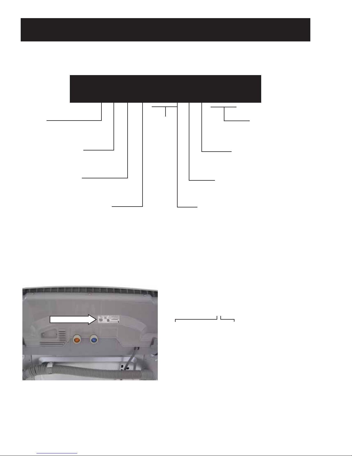
Using the Liquid Bleach
Dispenser
The bleach dispenser automatically
dilutes and dispenses liquid chlorine
bleach at the proper time in the wash
cycle.
1Check clothing care labels for special
instructions.
2Measure liquid bleach carefully,
following instructions on the bottle.
•Never pour undiluted liquid chlorine
bleach directly onto clothes or into
the wash basket.
•Do not pour powdered bleach into
bleach dispenser. Do not place load
items on top of the bleach dispenser
when loading and unloading the
washer.
•Avoid overfilling or splashing
when adding bleach to the
dispenser. The maximum capacity
of the bleach dispenser is one cup
of bleach per wash cycle. Overfilling
could result in early dispensing of
bleach.
3Before starting the washer, pour
measured amount of bleach directly
into bleach dispenser. If you prefer to
use powdered bleach, add it into the
wash basket directly before adding
clothes.
WARNING!
Do not mix
chlorine bleach with ammonia or acids
such as vinegar and/or rust remover.
Mixing can produce a toxic gas which
may cause death.
The manufacturer’s recommended
amount of undiluted bleach goes into the
bleach dispenser. During the final
“Infusor” wash action, the bleach is added
to the wash load. This ensures
performance won’t be diminished. Two
sequential flushes through the bleach
dispenser completely remove the bleach
from the dispenser. Any residual liquid left
in the dispenser at the end of the cycle is
water, not bleach. To prevent self-
siphoning of the bleach into the wash
basket and damage to your clothes, never
add more than the maximum fill level
marked on the dispenser.
Also keep clothes away from the bleach
dispenser so they don’t absorb any bleach
droplets left around the bleach dispenser.
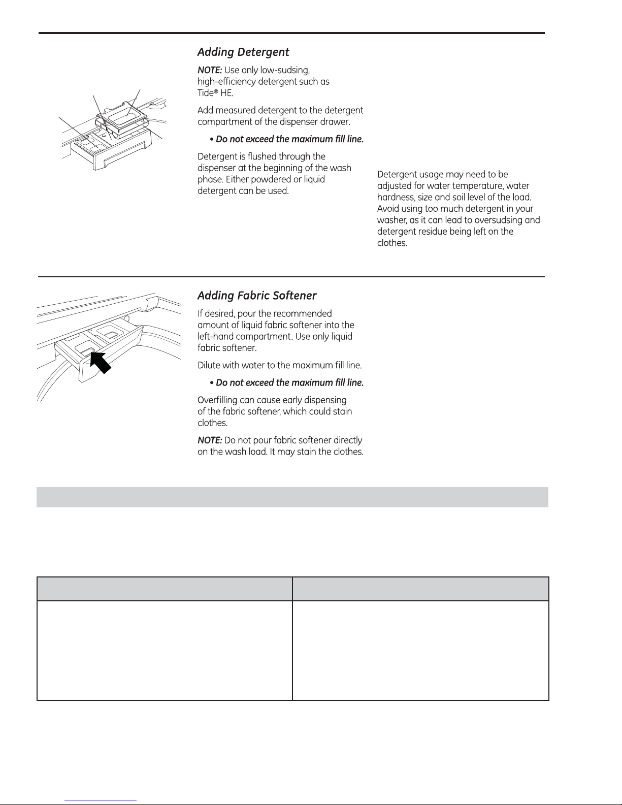
Using the Dispenser Drawer
The dispenser drawer contains
2 compartments:
•Liquid Fabric Softener
• Liquid or Powder Low-Sudsing,
High-Efficiency Detergent
The dispenser automatically dispenses
additives at the proper time in the wash
cycle.
1Slowly open the dispenser drawer by
pulling out the drawer until it stops.
2After adding laundry products, slowly
close the dispenser drawer. Closing the
drawer too quickly could result in early
dispensing of additives.
• Avoid overfilling or splashing when
adding laundry products to the
dispenser. Doing so could result in
early dispensing of laundry products.
At the end of the cycle, you may see
water in the compartments. This is part
of the normal operation of the washer.
NOTE: Do not use bleach in the dispenser
drawer.
TIDAL WAVE Wash System
Your washer has an innovative washing
system which uses rapid spinning
motion and an angled spray to pull
water through faberic. The TIDAL WAVE
Wash system provides a gentler and
more thorough cleaning.
TIDAL WAVE Wash is avaiable only
during COLORS/NORMAL and
WHITES/HEAVY DUTY cycles.
(Continued Next Page)

– 10 –
Main Wash
Liquid Detergent
Compartment
Insert
Main Wash
Powder Detergent
Compartment
Liquid Fabric
Softener
Compartment
When using liquid detergent, make sure
the liquid detergent compartment and
insert are in place. For powdered
detergent, remove both the liquid
detergent compartment and insert.
Powdered detergent will not dispense
with the liquid detergent compartment
and insert in place.
The washer control has demo mode that can be utilized to show user interface functionality. Once the user
presses the START button, the display shall rapidly count down (at approximately 100 times faster than
normal time), and illuminate the different cycle indicators on the 7-segment display.
To enter the demo mode: To exit the demo mode:
With the power connected and in the idle state (all
LCD and LED indicators off):
1. Press and hold the SOIL and the SPIN buttons,
then press the POWER button.
2. Press the START button.
1. Unplug the washer.
2. Wait 10-seconds.
3. Reconnect power to the washer.
Demo Mode

– 11 –
Operation Overview
Basic Wash Cycle
Note:See Component Locator Views for identification
and location of washer components.
After a load is placed in the basket, the user selects
the appropriate wash cycle and presses START.
Cycle time and wash patterns will vary depending
on user time adjustments, soil level adjustments,
fabric type, and wash-load weight.
Dry Load Sensing
Before an initial fill, the infusor rotates the dry
clothes load. This rotation is controlled by the power
board. The power board measures the amount of
time it takes for the motor to coast to a stop. The
larger the clothes load, the less momentum the
motor is capable of generating, so the faster it will
stop. The infusor will rotate back and forth up to
4 times. This information is used to determine the
initial water fill level.
Water Fill
The washer automatically fills to the proper
level based on the load sensing measurements.
Depending on the cycle chosen and the quantity
of clothes, there are 27 possible water levels. This
information is stored in memory for the final rinse at
the end of the wash cycle. Water levels are matched
to load size using approximately one-third less
water than typical top load washers.
Note: The washer can use as little as 16 gallons of
water for small loads and has an average water use
of 24 gallons per load.
Wet Load Sensing
After the first fill, the infusor and basket lock
together and rotate to measure the clothes load.
During this time, the motor momentum is measured
again. The washer compares this information to
the previous dry load sensing measurements and
determines if additional water is required.
Wash Water Temperature
During the fill, the washer monitors and regulates
wash water temperatures within 5°F (-15°C) of the
target temperature. This accuracy is achieved using
a thermistor located in the outer tub. The thermistor
monitors the tub water temperature during the fill
cycle.
Based on information received from the thermistor,
the power board controls the hot and cold inlet
valves to achieve the desired wash temperature.
(See Thermistor/ATC Control (Auto Temp.)
Target Water Temperatures:
Sanitize - 140°F (60°C)
Hot - 120°F (49°C)
Warm - 95°F (35°C)
Cold - 65°F (18°C)
During the fill, the basket slowly rotates in a
clockwise direction. This action mixes the detergent
and water to assure proper distribution and assure
the thermistor is reading an accurate basket water
temperature.
Tidal Wave Wash
The infusor and wash basket lock together and
rotate clockwise and then counterclockwise at
230 RPM. This action mixes the detergent and
water while distributing the clothes evenly in the
wash water. The basket wash speed is based on
fabric type and load size. Delicate fabrics are gently
rotated while heavier fabrics are rotated more
vigorously.
(Continued Next Page)
Centrifusion Wash
The locked infusor and wash basket begin a
clockwise spin (figure 1). The speed of the spin is
customized to the load type and fabric type. As the
basket spins faster, it creates a strong flow of water
under the centrifugal force (figure 2).

– 12 –
As water passes through the fabric, its natural
cleansing action washes away dirt without
damaging or tangling the fabric.
Water
Current
Fabric Soil
Infusor Wash
Following the centrifusion wash cycle, the basket
and infusor unlock and the wash basket remains
stationary. The infusor rotates to evenly distribute
the wash load while continuing to clean. The
redistribution of fabrics helps ensure that the lint
and dirt do not become trapped.
Jet Spray Rinse
Jet Spray is used during the rinse cycles in order to
use less water. Water is sprayed over the clothes as
the basket rotates.
Jet Spray is the default rinse type unless either
FABRIC SOFTENER or EXTRA RINSE cycle additions
are selected.
After several seconds of clockwise spinning, the
basket slows down and stops. The wash water pools
back into the wash basket. The wash basket starts
spinning in the counterclockwise direction creating
the same cleaning action. The washer will change
direction (up to 4 times) before going to the next
cycle.
Cycle Cancellation
If the user cancels a cycle by pressing the POWER
pad, after 4 minutes the pump will turn on and
pump the water out of the tub. The control does not
illuminate and the tub does not spin. The pump is
operated until the tub is empty.
If the customer pauses a cycle for an extended
amount of time, after 2 hours have elapsed, the
machine will pump the water out of the tub and
shut off.

– 13 –
Component Locator Views
Tub Cover
Balance Ring
Infusor
(Continued Next Page)
Motor
Wiring Harness
Top View (top cover removed)
Rear View (back cover removed)
* Overflow sensor located behind cabinet and near the left side of the drain pump.
Pressure Sensor Hose
Drain Pump
Overflow Sensor*
Suspension Rod
304 Stainless Steel Wash Basket

– 14 –
Underside of Top Cover
Component Tray (control panel in service position)
Pressure Sensor
RF Choke
Control Panel
Noise Filter
A/C Input
Water Valve Assembly
Control Cover
Bleach Dispenser Assembly
Dispenser Drawer Assembly
Lid Lock Assembly

– 15 –
Drain Pump
Clutch
ATC Thermistor
Heater
Motor Hall Sensor
Heater Thermostat
Underside of Washer

– 16 –
Power Board
Circuit Board Connector Locator View
Ground
ATC
Motor
Water Valve
Hall Sensor and Pressure Sensor
Heater Relay L
Drain Pump and Clutch Motor
Door Lock
Overflow Sensor
Display/Logic Connection 1
Heater Relay N
Display/Logic Board
LCD Display
Display/Logic Wire Harness 2
Display/Logic Wire Harness 1
Cycle Selector
Red LED*
* Red LED indicates that the power board is powered and awake.
Display/Logic Connection 2

– 17 –
Washer Components
Control Panel
The control panel must be removed to access the
control system components.
To remove the control panel:
1. Remove the 2 Phillips-head screws from the
bottom of the control panel cover.
Control Board Assembly
The control board assembly consists of the power
board and the display/logic board. Both are
attached to the control panel as one unit. Each
board is bonded to a plastic frame. The power
board has a red LED that indicates that the board
is powered and awake. (See Circuit Board Connector
Locator View.) The power and display/logic boards
are available separately.
To remove the control board assembly:
1. Remove the 3 Phillips-head screws from the top
of the control panel cover.
Note: To prevent damage to the control panel and
top cover, place a protective surface over the top
cover.
2. Tilt the control panel toward the front of the
washer to disengage 5 tabs from slots located in
the top cover.
3. Lay control panel face down on the top cover
(Service position).
Tabs
WARNING: Sharp edges may be exposed when
servicing the washer. Use caution to avoid injury.
Wear Kevlar gloves or equivalent protection.
2. Place the control panel in the service position.
(See Control Panel.)
3. Lift and remove the control panel cover.
4. Pull out and disengage the control cover from 4
tabs on the bottom of the control board.
5. Lift and remove the control cover from the
control board.
Service Position
(Continued Next Page)
Control Cover
Control Panel Cover

– 18 –
8. Carefully pull out the 5 plastic tabs that attach
the power and display/logic boards together.
6. Disconnect the wiring from the power board .
7. Remove the 10 Phillips-head screws that attach
the control board assembly to the control panel.
Remove the assembly.
9. Disconnect the 2 electrical connectors from the
power board.
Tab (1 of 5)
Water Valve
The water valve consists of a valve body and 5
solenoid coils. It is only available as a complete
assembly.
Each solenoid controls a specific water function.
When energized, there should be approximately
5-6 VDC at the appropriate coil.
Each coil on the water valve assembly has an
approximate resistance value of 30 Ω.
Pink colored plastic pressure fittings are used on
the water valve for a tight fit and to reduce the
possibility of leaks.
Note: Hot and cold water inlet screens are used to
prevent debris from entering the valve assembly.
Inlet screens can be removed by grasping hold of
the handle on the rear of the screen with a pair of
needle nose pliers and pulling it straight out. After
cleaning, insert for continued use.
To remove the water valve assembly:
1. Turn off the hot and cold water supply valves,
and then remove the fill hoses from the back of
the washer.
2. Place the control panel in the service position.
(See Control Panel.)
(Continued Next Page)
Note: The control panel, selector buttons, and pads
are replaced as a complete assembly.
Disconnect

– 19 –
6. Carefully lift and pull the water valve assembly
out of the water distribution system inlet.
Remove
Remove
Disconnect
Note: When installing the water valve assembly,
place valve with flanges inside the component tray
(as shown below).
Flanges
3. Note the placement of the wiring, and then
disconnect the wire harnesses from each coil.
4. Remove the 2 outlet hoses from the valve
assembly.
5. Remove the 3 Phillips-head screws that attach
the valve to the component tray.
Water Distribution System
The water distribution system consists of a multi-
function water valve, dispenser inlet, dispenser, and
bleach dispenser and jet spray outlet hoses.
Dispenser
Bleach Dispenser
Softener
Jet Spray
Cold Hot
Dispenser
Inlet
To remove the water distribution system:
1. Remove the water valve. (See Water Valve.)
2. Remove the 2 Phillips-head screws from the
dispenser.
3. Push the flange, located near each side of the
dispenser, outward to clear the tab.
Tab
Tab Tab
Flange Flange
(Continued Next Page)

– 20 –
Pressure Sensor
The pressure sensor is connected by a clear
pressure hose to an air reservoir near the bottom
of the outer tub and operates by a frequency (kHz)
signal to the power board.
• When the water level rises in the washer tub,
air is trapped in the reservoir. As the water level
rises, the air pressure in the reservoir increases.
• The pressure is translated into an electrical
signal (frequency) by the pressure sensor.
• The frequency will vary from approximately 27
kHz (empty tub) to 21 kHz (full tub).
• This frequency can be measured at the pressure
sensor between the purple and orange wires.
To remove the pressure sensor:
1. Place the control panel in the service position.
(See Control Panel.)
2. Disconnect the wire harness.
3. Push outward on the 3 flexible plastic tabs,
and then lift the pressure sensor from the
component tray.
4. Lift the dispenser from the component tray.
5. Remove the 2 Phillips-head screws that attach
the dispenser inlet to the dispenser.
6. Lift the dispenser inlet out of the dispenser.
Note: Pink plastic pressure fittings are used on
the dispenser inlet for a tight fit and to reduce the
possibility of leaks.
4. Squeeze and slide down the hose clamp.
5. Remove the pressure hose from the pressure
sensor.
Disconnect
Pressure Hose
Hose Clamp
Other manuals for Profile PTWN8055MMS
2
This manual suits for next models
1
Table of contents
Other GE Washer manuals

GE
GE WLSR3000G5WW User manual

GE
GE GTWS8655DMC Assembly instructions

GE
GE Profile PTWN6050MWT Assembly instructions

GE
GE 175D6444P001 User manual

GE
GE GFW148 Original instructions

GE
GE WPSE7003A User manual

GE
GE GFWR4805 User manual

GE
GE WWA8836M User manual

GE
GE WWA8330V User manual

GE
GE WWA8608MAL User manual