GEAX
s.r.l Chapter 1
OPERATOR TRAINING
1.5 Symbols used in this manual
Danger (or other) signs are used at various points in the manual to call the reader’s
attention to issues regarding potentially dangerous activities.
Situation, procedure, context or other factor that can lead to increased risk.
Situation, procedure, context or other factor that can lead to increased risk of
electrocution.
Situation, procedure, context or other factor that can lead to increased risk of
getting caught and dragged by rotating parts.
Situation, procedure, context or other factor that can lead to increased risk of
fire.
Situation, procedure, context or other factor that can lead to increased risk of
scalding on parts that become hot during operation.
Situation, procedure, context or other factor that can lead to increased risk of
intoxication or poisoning by harmful substances.
Situation, procedure, context or other factor that can lead to increased risk of
intoxication or poisoning by harmful substances.
Situation, procedure, context or other factor that can lead to increased risk of
burning by corrosive substances.
Situation, procedure, context or other factor that can lead to increased risk of
loss of balance and falling.
Situation, procedure, context or other factor that can lead to increased risk of
being hit by the machine in movement.
Situation, procedure, context or other factor that can lead to increased risk of
being hit by the machine in movement.
Situation, procedure, context or other factor that can lead to increased risk of
crushing hands.
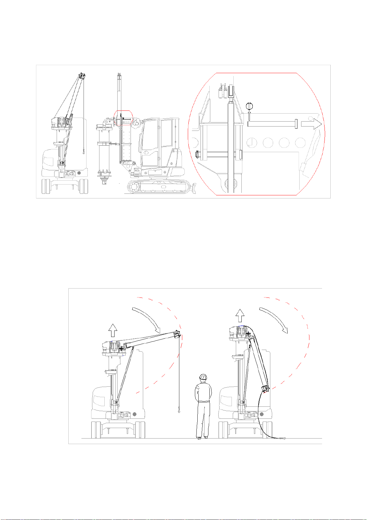
Situation, procedure, context or other factor that can lead to increased risk of
being hit by suspended loads falling down.
Improving safety measures is a never-ending task; should you encounter a potentially
hazardous situation that is not adequately covered in this manual, please let us know.