Operation
10 3A0413B
Spraying
1. Unlock trigger lock.
2. Be sure the arrow shaped tip faces
forward (spray).
3. Hold gun perpendicular and
approximately 12-inches (30 cm) from
surface. Move gun first, then pull gun
trigger to spray a test pattern.
4. Slowly increase pump pressure until
coverage is uniform and even (see
sprayerinstructionmanualforadditional
information).
Aligning Spray
1. Perform Pressure Relief Procedure,
page 8.
2. Loosen tip guard retaining nut.
3. Align tip guard horizontally to spray a
horizontal pattern.
4. Align tip guard vertically to spray a
vertical pattern.
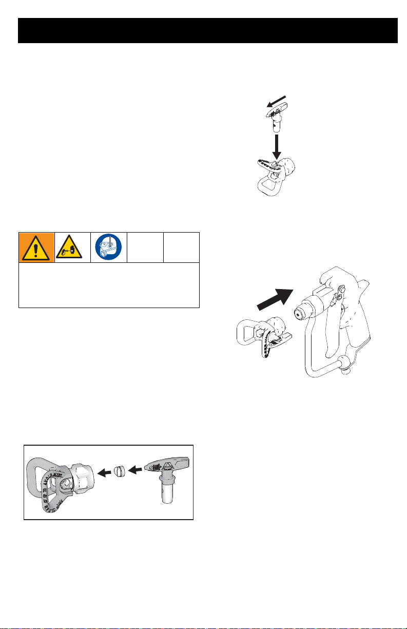
Clear Tip Clog
In the event that particles or debris clog the
spray tip, this sprayer is designed with a
reversible spray tip that quickly and easily
clearstheparticleswithoutdisassemblingthe
sprayer.
1. Engage trigger lock. Rotate spray tip to
unclog position. Disengage trigger lock.
Trigger gun at waste area to clear clog.
NOTE: If spray tip is difficult to rotate when
turning to the unclog position, perform
Pressure Relief Procedure, page 8, then
turn Prime/Spray valve to spray position and
repeat step 1.
2. Engage trigger lock. Rotate spray tip
back to spray position. Disengage
trigger lock and continue spraying.
Cleanup
Flush gun after each work shift and store in a
drylocation.Donotleavethegunoranyparts
in water or cleaning solvents.
Maintenance
To avoid personal injury, always read all
warnings in this manual, and the
equipment manual, before performing any
maintenance on the gun.
ti29221a