GefenTV GTV-DD-2-AA User manual


1
INTRODUCTIO
N
Congratulations on your purchase of the Digital Audio Decoder. Your complete satisfaction is very important to us
.
G
efenTV
G
e
f
enTV is a unique product line catering to the growing needs
f
or innovative home theater solutions. We specialize in
total integration
f
or your home theater, while also
f
ocusing on going above and beyond customer expectations to ensure
you get the most
f
rom your hardware. We invite you to explore our distinct product line and hope you
fi
nd your solutions..
Don’t see what you are looking
f
or here
?
Please call us so we can better assist you with your particular needs.
.
T
he GefenTV Digital Audio Decoder
The GefenTV Digital Audio Decoder takes audio encoded in Dolby Digital (at up to 5.1 channels) from your multichan-
nel S/PDIF or T
O
SLINK digital audio source and converts it to L/R analog audio -- without the need for any other
external equipment!
With the GefenTV Digital to Analog Decoder you can listen to digital audio sources such as DVD and CD players or
digital computer audio on your legacy analog sound system, preserving your current investment
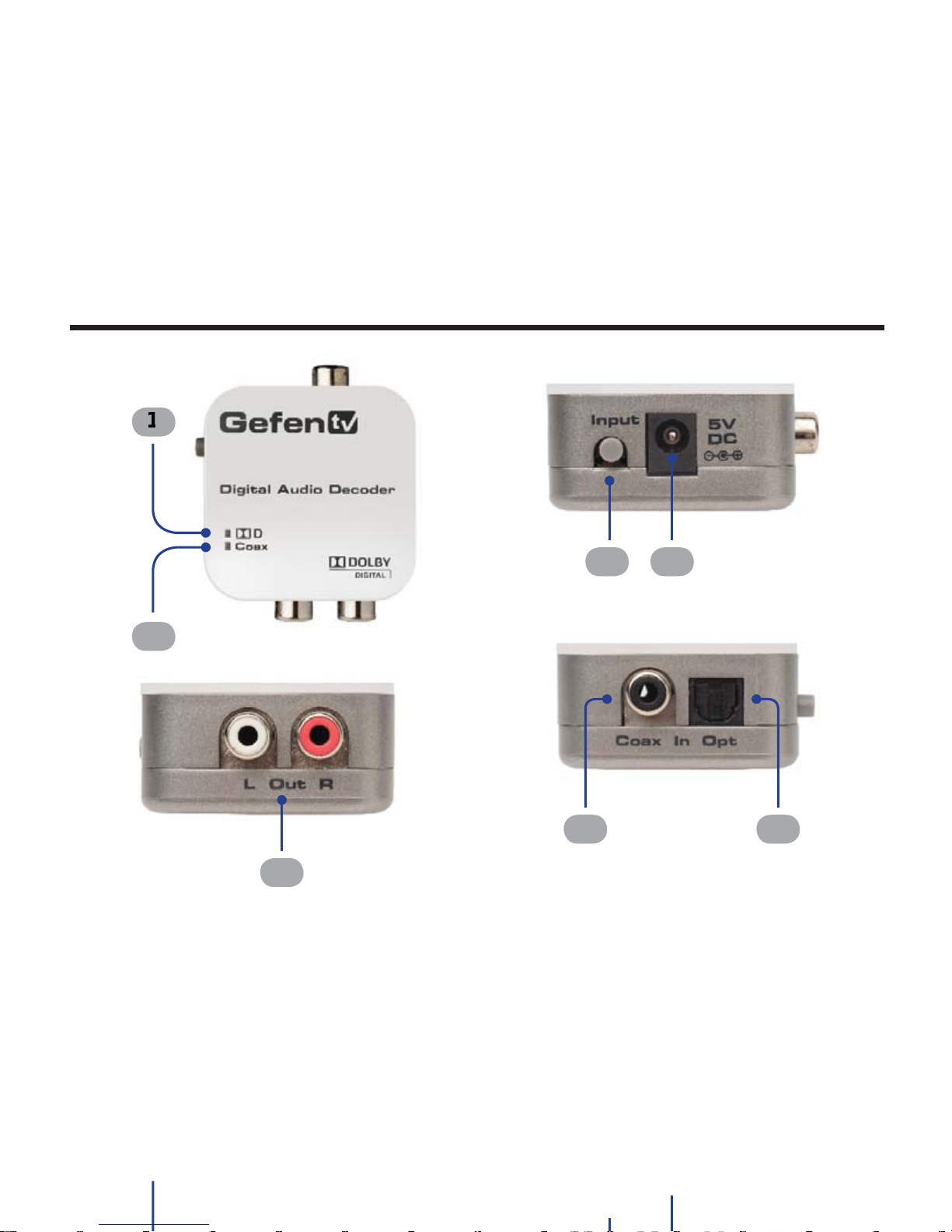
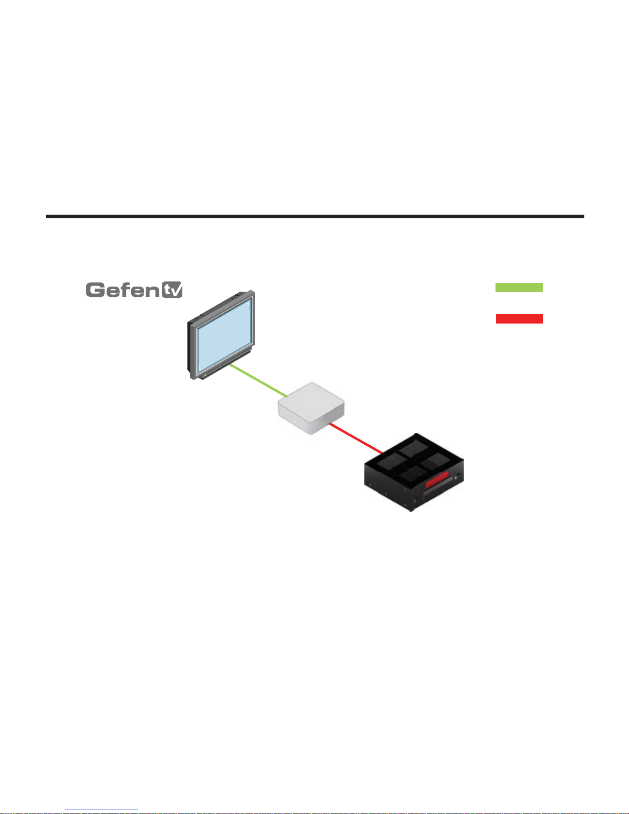
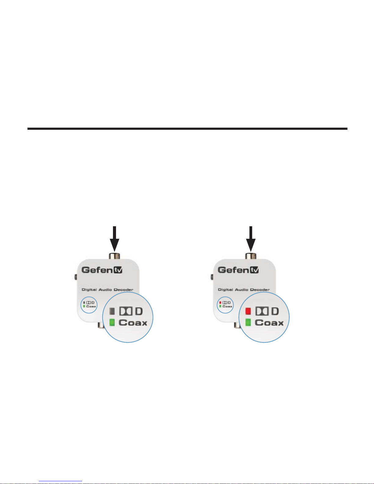
.
How It Works
A coaxial or optical audio output on your digital audio source connects into the input on the Digital to Analog Decoder.
The input type is chosen with the Decoder’s selector button. The Decoder is connected to power. Analog RCA connec-
tors on the Decoder output L/R analog audio to powered speakers
.

OPERATION NOTE
S
2
READ THESE NOTES BEFORE INSTALLING OR
OPERATING THE GEFENTV DIGITAL AUDIO DECODER
• This decoder supports both Linear PCM and Dolby Digital audio input formats.
• The Digital Audio Decoder is not an amplification device and cannot be used directly with
earphones or other passive devices.
• Do not use this decoder with a power supply other than the one that is provided.
arphones or other passive devices.
• Do not use this decoder with a power supply other than the one that is provided.

3
FEATURE
S
Features
• Converts S/PDIF or T
OS
LINK digital audio to L/R analog audio
• Digital interpolation filter and digital to analog converter (DAC)
•
S
upports up to 6 channels (up to 5.1 Surround) of audio encoded in Dolby Digital
• Auto samples at frequencies of 32, 44.1, 48 kHz
• 24-bit incoming bitstream on left and right channels
• Allows listening to digital audio sources on legacy analog sound systems
• Compact and easy to install
Package Includes
(1) Digital Audio Decoder
(1) 5V DC Power Suppl
y
(
1
)
User Manual
• 24-bit incoming bitstream on left and right channels
• Allows listening to digital audio sources on legacy analog sound systems
• Compact and easy to install
Package Includes
(1) Digital Audio Decoder
(1) 5V DC Power Suppl
y
(1) User Manual

4
U
NIT LAYOUT
1
2
3
4 5
6
7
2
3
4 5
6
7

5
U
NIT DESCRIPTION
S
1
Dolby Digital
This LED indicator will glow bright red when a DolbyDigital signal is detected on the input.
2
Coa
x
This LED indicator will glow bright green when the Coax input is activated.
3Out (L/R
)
Connect L/R RCA stereo cables from these audio outputs to an external amplifier.
4
Coax In
Use a coax audio cable to connect an external digital audio source to this S/PDIF connector.
5
Opt In
Use an optical cable to connect an external digital audio source to this T
OS
LINK connector.
6
5V D
C
Connect the included 5V DCpower supplyto this power receptacle.
O
nlyuse the power supplythat
is included with this product.
7
Inpu
t
Press this button to toggle between Coax (S/PDIF)and
O
ptical (T
OS
LINK)inputs.

6
CONNECTING THE DIGITAL AUDIO DECODER
How to Connect the Digital Audio Decoder
1.
Connect a Coax and/or
O
ptical cable between the audio source and the S/PDIF and/or T
O
SLINK
c
onnectors on the Digital Audio Decoder.
2. Connect a pair of L/R RCA-type cables between the L/R output connectors on the Digital Audio
Decoder and the
3
. Connect the included 5V DC power supply to the power receptacle on the Digital Audio Decoder.
4. Connect the AC power cord to an available electrical outlet.
Decoder and the
3
. Connect the included 5V DC power supply to the power receptacle on the Digital Audio Decoder.
4. Connect the AC power cord to an available electrical outlet.

7
WIRING DIAGRA
M
WiringDiagram for the Digital Audio Decoder
GTV-DD-2-AA
TV with TOSLINK Audio
Output
Analog Audio Receiver
DIGITAL AUDIO CABLE
(Up to 200 ft)
ANALOG AUDIO CABLE
In
Out
I
n
Converter
GTV-DD-2-AA

8
OPERATING THE DIGITAL AUDIO DECODER
Coax LED =
O
FF, Dolby LED =
O
FF
Active Input:
O
ptical (T
OS
LINK
)
Audio Type: Linear PCM
Coax LED =
O
FF, Dolby LED = RE
D
Active Input:
O
ptical (T
OS
LINK)
Audio Type: Dolby Digital
LED Indicators
The following illustrations below show the different states of audio input and the audio type which is
displayed by the LED indicators on the Digital Audio Decoder. Pressing the Input button switches
between Coax and
O
ptical inputs.
D
olby Digita
l
L
inear PC
M

9
OPERATING THE DIGITAL AUDIO DECODER
Coax LED = GREEN , DolbyLED =
O
FF
Active Input: Coax (S/PDIF)
Audio Type: Linear PCM
Coax LED = GREEN , Dolby LED = RE
D
Active Input: Coax (S/PDIF)
Audio Type: Dolby Digital
Linear PC
M
D
olby Digital

10
SPECIFICATION
S
Audio Inputs.............................................................................................................(1) Coax / (1) T
OS
LIN
K
Audio
O
utputs............................................................................................................Analog L/R, RCA-typ
e
Output Impedance...............................................................................................................................500 Ω
O
utput Voltage......................................................................................................1.8V RMS
@
0 dB (max.)
Frequency Response..................................................................................................................< +/-0.5 dB
S
ignal-to-Noise Ratio........................................................................> 90 dB (20 Hz - 20 kHz A-Weighting)
Power Supply......................................................................................................................................5V DC
Power Consumption....................................................................................................................5 W (max.)
O
perating Temperature.............................................................................................................0° C ~ 70°
C
Dimensions..............................................................................................................1.7” W x 0.9” H x 1.6” D
S
hipping Weight.....................................................................................................................................1 lb.

1
1
11
WARRANTY
Gefen warrants the equipment it manufactures to be free from defects in material and workmanship.
If equipment fails because of such defects and Gefen is notified within two (2) years from the date o
f
shipment, Gefen will, at its option, repair or replace the equipment, provided that the equipment has not
been subjected to mechanical, electrical, or other abuse or modifications. Equipment that fails under
c
onditions other than those covered will be repaired at the current price of parts and labor in effect at the
time of repair. Such repairs are warranted for ninety (90) days from the day of reshipment to the Buyer.
This warranty is in lieu of all other warranties expressed or implied, including without limitation, any
implied warranty or merchantability or fitness for any particular purpose, all of which are expressly
disclaimed.
1. Proof of sale may be required in order to claim warranty.
2. Customers outside the US are responsible for shipping charges to and from Gefen.
3
. Copper cables are limited to a 30 day warranty and cables must be in their original condition.
The information in this manual has been carefully checked and is believed to be accurate. However,
G
e
f
en assumes no responsibility
f
or any inaccuracies that may be contained in this manual. In no event
will Gefen be liable for direct, indirect, special, incidental, or consequential damages resulting from any
defect or omission in this manual, even if advised of the possibility of such damages. The technical
information contained herein regarding the features and specifications is subject to change without
notice.
no
ti
ce
.
For the latest warranty coverage information, please visit Gefen’s Warranty web page a
t
www.gefen.com.
PRODUCT REGISTRATION
P
lease register your product online by visiting the Register Product page under the Support
section of the Gefen Web site
.
Table of contents
Other GefenTV Media Converter manuals

GefenTV
GefenTV GTV-HDMI-2-HDMIAUD User manual

GefenTV
GefenTV GTV-VOLCONT-D User manual

GefenTV
GefenTV GTV-COMPSVID-2-HDMIS User manual

GefenTV
GefenTV GTV-DVIDL-2-MDP User manual

GefenTV
GefenTV GTV-HDMI-1080PS User manual

GefenTV
GefenTV GTV-192KUSB-2-ADAUD User manual

GefenTV
GefenTV GTV-HDMI-2-HDMIAUD User manual

GefenTV
GefenTV GTV-HIDEFS User manual

GefenTV
GefenTV GTV-HDMI-2-COMPSVIDS User manual

GefenTV
GefenTV HDMI-2-COMPSVIDS User manual