manuals.online logo
Brands
  1. Home
  2. •
  3. Brands
  4. •
  5. Ashland Earthmovers
  6. •
  7. Construction Equipment
  8. •
  9. Ashland Earthmovers I-110TS2 User manual

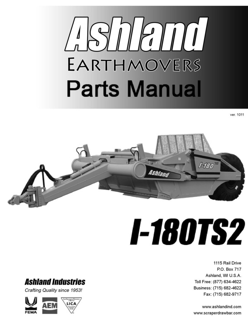
Ashland Earthmovers I-110TS2 User manual

I-110TS2
PARTS MANUAL
Ashland Industries Inc.
1115 Rail Drive
P.O. Box 717
Ashland, WI. 54806
Ph: 877-634-4622 Toll Free
Ph: 715-682-4622
Fx: 715-682-9717
www.ashlandind.com
ver 808-22015
I-110 TS2
HOW TO ORDER PARTS:
IMPORTANT
Parts must be ordered through your local authorized ASHLAND dealer.
Be sure to state MODEL and SERIAL NUMBER of your machine, PART NUMBER, DESCRIPTION and
QUANTITY needed.
Unless this is done, we cannot provide prompt service or assure shipment of the correct parts.
A
shland Industries weldable replacement parts are available to rebuild, modify or update your
scraper to current factory specifications.
INDEX
Page 2. Safety Guidelines
Page 3.-4. Operators and Maintenance Instructions
Page 4.-5. Swivel Hitch – Illustration and Parts List
Page 6. Front End Assembly -Illustration and Parts List
Page 7. Apron Assembly – Illustration and Parts List
Page 8. Bowl and Frame – Illustration and Parts List
Page 9. Push-Off Gate Assembly – Illustration and Parts List
Page 10. Rear Wheel and Hub Assembly – Illustration and Parts List
Page 11. Lift Cylinder (5” x 16”) – Illustration and Parts List
Page 12. Apron Cylinder (4” x 13”) – Illustration and Parts List
Page 13. Push-Off Cylinder (4” x 54”) – Illustration and Parts List
Page 14.-16. Hydraulic Valve –Identification, Illustration, Parts List and Adjustment
Page 17-20. Service Manual Appendix
Page 21. Troubleshooting
Page 22. Warranty Statement
Ashland Industries Toll-free:877-634-4622 Fax:715-682-9717
Page #1
I-110 TS2
SAFETY SIGNAL WORDS
Note the use of the signal wordsDANGER, WARNING and CAUTION with the safety messages. The appropriate signal
word for each hasbeen selected using the followingguidelines:
DANGER: Indicates an imminently hazardous situation that, if not avoided, will result in death or serious injury.
This signal word is to be limitedto the mostextreme situations typically for machinecomponents which, for functional
purposes, cannot be guarded.
WARNING: Indicates a potentially hazardous situation that, if not avoided, could resultin death or serious injury,
and includes hazards that are exposed when guardsare removed. It may also be used to alert against unsafe
practices.
CAUTION: Indicates a potentially hazardous situation that, if not avoided, may result in minor or moderate injury.
Itmay also be used to alert against unsafe practices.
GENERAL SAFETY GUIDELINES
Safety of the operator isone of the main concerns in designing and developing a newpiece of equipment. Designers and
manufacturers build in as many safety features as possible. However, every year many accidents occur which could have
been avoided by afew seconds of thought and a more careful approach to handling equipment. You, the operator, can
avoid many accidents by observing thefollowing precautions in this section. To avoid personal injury, study the following
precautions and insist those working with you, or for you,follow them.
Replace any CAUTION, WARNING, DANGER or instruction safety decal that is not readable oris missing. Location of
such decals is indicated in this booklet.
Do not attemptto operate this equipmentunder the influence of drugs or alcohol.
Review the safety instructions with all users annually.
This equipment is dangerous to children and persons unfamiliar with its operation. The operator should be a responsible
adult familiar with farm machineryand trained in this equipment’s operations. Do not allow persons to operate or
assemble this unit until they have read this manual and have developed a thorough understanding of the safety
precautions and of how it works.
Toprevent injury or death, use a tractor equipped with a Roll Over Protective System (ROPS). Do notpaint over, remove
or deface any safety signs orwarning decals on your equipment. Observe all safety signs and practice the instructions on
them.
Never exceed the limits of a piece of machinery. If its ability todo a job, or to do so safely,is in question - DON’T TRY IT.
Ashland Industries Toll-free:877-634-4622 Fax:715-682-9717
Page #2
I-110 TS2
OPERATORS AND MAINTENANCE INSTRUCTIONS
This scraper is a durable piece of equipment and with proper care will yield many years of trouble
free operation. The scraper requires a power source with TWO 4 way (double acting) hydraulic
control valves.
The scraper should be
g
reased at all points where
g
rease fittin
g
s are provided. Connect hydraulic
hoses to the tractor and retract lift cylinders to REMOVE TRANSPORT LOCK PINS (point A), then
extend and retract all cylinders several times to force out any air from the hydraulic cylinders and
lines. Check the oil levels in the tractor hydraulic system and add to maintain the proper level. Care
should be used when addin
g
oil or when disconnectin
g
any oil line to keep all dirt out of the oil as dirt
is a major factor in the failure of hydraulic components.
When the scraper is placed into operation, the operator will have to “feel out” the amount of
depth of cut to obtain maximum loading efficiency. This is usually accomplished by taking a lesser
and more uniform cut; however, some soil conditions such as loose sand may require a “pumping
action” obtained by taking successive deep cuts and lifting out of cut as the tractor begins to lose
power or traction.
1. After 10 hours work, all bolts should be checked and tightened if necessary.
2. Every 10 hours all grease fittings should be lubricated.
3. After 50 hours work, all bolts should be rechecked and tightened if necessary.
Check wheel bearings and adjust if necessary.
4. After 300 hours work, clean and repack wheel bearings and replace, if necessary,
cuttin
g
ed
g
es
,
worn
p
ins
,
etc.
Ashland Industries Toll-free:877-634-4622 Fax:715-682-9717
Page #3
I-110 TS2
Safety-Tire Warning
WARNING
Check Tires and Wheels
The task of servicing tires and wheels can be extremely dangerous and should be
performed by trained personnel only, using the correct tools and following specific
procedures. Do not attempt to mount, demount or inflate atire if you do not have
the proper equipment and experience to perform the job. Call a qualified repair
service to inspect the assembly and make necessary repairs. Failure to heed
warnings could lead to serious injury or death.
Visually inspect tires and wheels daily. Carefully inspect any rim and tire assembly that
has been run underinflated or flat before reinflating the tire to make sure there is no
damage to either the rim or tire.
•ALWAYS wear personal protection equipment such as gloves, footwear, eye
protection, hearing protection and head gear when servicing tire and wheel
components.
•DO NOT operate with damaged rims, tire cuts or bubbles, missing lug bolts or
nuts or damaged rims.
•ALWAYS maintain the correct tire pressure. NEVER exceed recommended tire
inflation pressure.
•INSPECT any rim and tire assembly that has been run flat or severely
underinflated before reinflating the tire. Damage to the rim and tire may have
developed.
•NEVER reinflate a tire that has lost air pressure or has been run flat without
determining and correcting the problem.
•NEVER try to repair wheel, rim, or tire components parts. Parts that are
cracked,worn, pitted with corrosion,or damaged mustbediscarded,and replaced
with good parts.
•ALWAYS use approved tire and rim combinations for the model scraper that you
have and verify that part numbers of components are correctly matched for the
assembly.
•ALWAYS exhaust all air from the tire prior to demounting.
•ALWAYS place wheel and tire assemblies in restraining devices (safety cage)
when inflating tires. Use a clip-on chuck and long extension hose to allow you to
stand to the side of the tire and not in front of it.
•NEVER weld or cut on an inflated tire assembly. Welding heat can cause
increased pressure which could result in tire explosion.
•ALWAYS use proper lifting techniques, and mechanized lifting aids to move
heavy components and assemblies.
•NEVER leave a tire, wheel, or assembly unsecured in a vertical position.
•ALWAYS take care when moving tires and wheels that other people in the area
are not endan
g
ered.
Ashland Industries Toll-free:877-634-4622 Fax:715-682-9717
Page #4
I-110 TS2
Swivel Hitch Assembly used on S/N 21582 and above
Key Number Part Number Description
1A125223-01 Yoke: A-Frame
1A123299-07 Pin: Two Ear Drawbar To Hitch
2A125223-02 Swivel
3A125223-03 Bracket: 10 Hole
4A125223-04 Pin: Main Vertical
5A125223-05 Spacer: 6”
6A125223-06 Pin Horizontal
7A125223-07 Bushing
8A125223-08 Seal: O-ring
9A125223-09 Seal: O-ring
10 AFH-00028 Grease Fitting: 90°
11 A125223-11 Washer- 1-1/2” For Horizontal Pin
12 A125223-12 Nut: Slotted 1-1/2” NC
13 A125223-13 Spacer: 6”
14 A125223-14 Washer: 2 1/2”
15 A125223-15 Nut: Slotted 2-1/2” NC
16 A125223-16 Sleeve: 2” Rubber
17 A125223-17 Cap: For Vertical Pin
18 A125223-18 Pin: Cotter 3/8 x 5”
19 14505 Grease Fitting Straight
20 8613 Cotter Pin: 5/16 x 2-1/2”
21 A125056-24 Bushing
22 A125056-27 Bushing
23 A123299-08 4 Ear Drawbar Hiitch Pin
24 A123299-07 2 Ear Drawbar Hitch Pin
25 AFN-00014 1 1/2 Slotted Nut
26 AFP-00001 1/4 X 3 Cotter Pin
Ashland Industries Toll-free:877-634-4622 Fax:715-682-9717
Page #5
I-110 TS2
Front End Assembly
Key Number Part Number Description
1 A123292 Front End Assembly
2 A123456 Trunion Mount Block
3 A14039 Bushing, 2-3/8” OD x 2” ID x 2” Long with Grease
Passage"
4 A10152A Frame Attachment Pin, 2” x 8-1/16”
5 A123292-17 Travel Lock
6 A125006 Safety Snap Pin
7 AFB-00054 Bolt: 1/2” x 3-1/2” w/7500 Nut
8 A125179 Bushing
9 AFB-00021 Bolt: 1 X 5 1/2 NC Gr. 8 -(7 req.)
10 AFN-00037 Nut: 1" NC Locknut (7 req.)
11 14505 Grease Fitting 1/8 NPT
12 AHF-00028 90 deg. Grease Fitting
Ashland Industries Toll-free:877-634-4622 Fax:715-682-9717
Page #6
I-110 TS2
Apron Assembly
Key Number Part Number Description
1A123340 Apron
2A16027 Bushing, 2" OD X 1 1/2" ID X 2" L
3A123337 Pin, 1 1/2 X 5 3/8 L
47450 Nut: 3/8 NC
514505 Grease Fitting
6AFB-00049 Bolt 3/8 NC X 3"
Ashland Industries Toll-free:877-634-4622 Fax:715-682-9717
Page #7
I-110 TS2
Bowl & Frame Assembly
Blade BoltsRequire
d
:
Qty
A123331 (& Ser) PB9P-NC-088-0275 (12)
A123332L & R PB9P-NC-088-0275 (4)
PB9P-NC-088-0225 (2)
A123338L & R PB9P-NC-088-0275 (4)
PB9P
-
NC-088-0225
(
3
)
Key Number Part Number Description
1A123302 Bowl and Frame I-110TS
2AFB-00094 Flange Bolt, 3/8” NC x 1”
3A123309-62L Apron Cylinder Guard-Left
4A123309-62R Apron Cylinder Guard-Right
5A123332R Right cutting edge, 8”
6A123331 Center cutting edge, 12” x 54”
A123331SER Optional Serrated cutting edge
7A123332L Left cutting edge, 8”
8PB9P-NC-088-0275 Plow bolt, 7/8” NC x 2-3/4”
9A123338L Left Bank Shaver Side Blade
10 A123338R Right Bank Shaver Side Blade
11 AFN-00019 Nut: 7/8” NC
12 PB9P-NC-088-0225 Plow bolt, 7/8” NC x 2-1/4”
13 AFN-00026 Nut: 7/8” NC Jam
14 A125019 Grease Fitting
15 A125026 Bulkhead Nut
16 A123309-89 Single Hole Tab
17 A125022 18" Grease Line
Ashland Industries Toll-free:877-634-4622 Fax:715-682-9717
Page #8
I-110 TS2
Push Off Gate
Key Number Part Number Description
1A10159 Brace: (L.H. & R.H. same)
2AFN-00006 Nut: 3/4" NC
3AFB-00037 Bolt: 3/4" NC X 2" L
4AFW-00002 Lockwasher: 3/4"
57500 Nut: 1/2 NC
6A10171 Dirt Shield
7AFB-00019 Bolt: 1/2" X 1 1/2" NC Bolt
8A10160 Pushoff Gate: Model I-110
9A123305A Pin: 1 1/4" X 2 3/4"
10 A123353 Wear Pad
11 AFP-00001 Cotter Pin: 1/4 X 3
12 A6007A Pin: 1 1/4" X 4 1/8" L
13 A10163 Bushing: 1 3/4" OD X 1 1/4" ID
14 AFB-00033 Bolt: 1/2 NC X 2 1/2" Gr. 8
15 A123323 Pin: 1 1/4" X 4 1/8" Tab Head
16 A10164 Roller: 4 1/4 OD X 1 3/4 ID
17 A125020 32" Grease Line
18 A123323-40 Double Hole Tab
19 A125026 Bulkhead Nut
20 A125021 54" Grease Line
21 A125019 Greasefitting 1/4-28 54" L
22 8100 Lockwasher: 1/2"
23 7036 Bolt: 1/2" NC X 2" Gr. 8
Ashland Industries Toll-free:877-634-4622 Fax:715-682-9717
Page #9
I-110 TS2
Rear Wheel, Spindle & Hub Assembly
Key Number Part Number Description
1A14035 Wheel - 17” x 25”
2A14038 Lock Ring
3A14008 O-Ring
4A14015 Bearing cone
5A14014 Bearing Cup
6A14010 Hub
7A14013 Bearing Cup
8A14012 Bearing Cone
9A14011 Grease Seal
10 A10176 Stud
11 A10046 Lug Nut
12 A10048 Spindle Nut
13 A10049A Lock Collar
14 A10172 Nut with lock pin
15 A14037 Spindle
16 AFN-00001 Nut, 1"" NF Toplock
17 AFB-00017 Bolt, 1” NF x 6-1/2” lg.
18 A14036 Slide Ring
19 A14016 Valve Stem
20 A14004 Hub Cap
22 AFB-00080 Bolt, 5/16” NC x 1/2” lg.
23 A14037E Extended spindle plate
24 A14037P Cross Pipe
25 AFB-00092 Bolt: 1” NFX 4 Lg, 8 Reg
26 AFN-00001 Nut: 1” NF Top Lock, 8 Reg
Ashland Industries Toll-free:877-634-4622 Fax:715-682-9717
Page #10
I-110 TS2
Lift Cylinder 5" x 16" Trunion Mount
Key Number Part Number Description
1A123324-1 2-1/2” Rod
2A123324-2 Barrel Weldment
3A125159-34 1-3/4 NF Locknut
4A123324-4 Piston
5A123324-5 Gland
6A123324-6 Rod Seal
7A123324-3 Wear Band
8A123324-8 Wear Ring
9A123324-9 Piston Seal (2-pc.)
10 A123324-10 O-ring
11 A123324-11 O-ring
11 AHS-00140 Seal Kit (Items 6-12)
12 A123324-7 Rod Wiper
13 A123381 Pin 1-1/2” x 10-3/4”
14 AFP-00002 1/4” x 3” Cotter Pin
Ashland Industries Toll-free:877-634-4622 Fax:715-682-9717
Page #11
I-110 TS2
Apron Cylinder 4" x 13"
Key Number Part Number Description
1A125050-01 Rod 1-3/4” with welded eye
2A125050-02 Piston
3A125050-03 "Gland, Threaded"
4A125050-04 Lock Nut, 1-1/8” NF
5A125050-05 Seal Kit, a-f
5a A125050-05a Nylon Wear Ring
5b A125050-05b FSP Seal
5c A125050-05c O-Ring
5d A125050-05d Backup Washer
5e A125050-05e Hallite Rod Seal
5f A125050-05f Snap-in Rod Wiper
6A123351 Pin Keeper Bushing
7AFB-00019 1/2" X 1 1/2" GR 8 NC Bolt
8A123362 Pin: Rod End
9A123363 Pin: Barrel End
10 8602 Cotter Pin: 1/4 X 2
Ashland Industries Toll-free:877-634-4622 Fax:715-682-9717
Page #12
I-110 TS2
Push Off Cylinder
Key Number Part Number Description
A125176 Push Off Cylinder
1A125176 Barrel Weldment
2A125176-20 Shaft
3A125176-32 Spacer
4A125176-30 Piston
5A125176-31 Head
6A125175-33 1 1/4" Nylock Nut
7A125176-40 Seal Kit
8A125175-35 Bearing
9A125175-36 Snap Ring
10 A125175-37 Grease Zerk
11 8602 1/4" X 2" Cotter Pin
12 A14033 Pin: Rod End
13 A9024 Pin: Barrel End
Ashland Industries Toll-free:877-634-4622 Fax:715-682-9717
Page #13
I-110 TS2
Hydraulic Manifold Assembly
IMPORTANT: This Hyd. Manifold was integrated into production April, 2006 It replaces A125070
valve.
For older machines see master parts book on Ashlandind.com.
HYDRAULIC MANIFOLD ASSEMBLY
A125174
SETTING THE APRON AND PUSHOFF VALVE
The manifold block containing the pushoff sequence valve cartridge and apron sequence valve cartridge is used
to control two hydraulic circuits with one hydraulic remote. when the tractor hydraulic remote is activated, oil flows first to
the apron cylinders until they are fully extended. Once the cylinders are fully extended, the apron circuits’ hydraulic
pressure begins to increase. Once the pressure threshold is surpassed (which is adjustable. See adjustment section),
the sequence valve diverts the oil flow to the pushoff’s hydraulic circuit. Once the push off is completely extended the
operator then reverses the tractorshydraulic remote. The counterbalance valve will hold the apron open until the push off
is fully retracted. The Apron sequence valve then opens and allows the apron to close.
Setting the valves:
STEP 1 PUSHOFF SEQUENCE VALVE
Loosen the lock nut (9/16”) on thesequence valve cartridge. Turn the setscrew (4mm)clockwise until the front
apron rises before the push-offbegins to advance. (Earthmover should be empty) Turnthe adjustment screw an
additional 1/4 turn clockwise and tighten jam nut.
STEP 2 Counter Balance VALVE
Loosen the lock nut (9/16”) on thecounterbalance valve cartridge. Turn the setscrew (4mm) counter-clockwise
until the apron holds in a raised position while rear gate is being retracted. Turn adjustment screw anadditional 1/4 turn,
ti
g
hten
j
amnut. DO NOT ti
g
hten ad
j
ustin
g
screw morethan necessar
y
.
Key Number Part Number Description
1A125162-01 COUNTERBALANCE CARTRIDGE
2A125162-02 SEQUENCE CARTRIDGE
Ashland Industries Toll-free:877-634-4622 Fax:715-682-9717
Page #14
I-110 TS2
Hydraulic Valve Assembly Ports
Key Number Description
ASupply Line
BPushoff Cyl. (Rod End) -Apron Cyl., Right side (Rod
End)-Supply Line
CPushoff Cylinder, (Base End)
DApron Cylinder, Right Side, (Base End)
EApron Cylinder, Left side, (Rod End)
FApron Cylinder, Left Side, (Base End)
CBGB Counterbalance Valve, adjustable
SCGA Sequence Valve, adjustable
GA Pressure test port
GB Pressure test port
Ashland Industries Toll-free:877-634-4622 Fax:715-682-9717
Page #15
I-110 TS2
Hydraulic Valve Seal Kit
ITEM PART NO. DESCRIPTION
1 AHA-00076 Adapter: Str. Swiv ½ MP X ½ FP. 109 Rest
2 AHA-00043 Adapter: Str. Sw. 1 1/16 M ORB X ½ FP
3 AHA-00048 Adapter: 90 Deg. Swiv. 1 1/16 M ORB X ½ FP
4 AHA-00046 6 ORB Plug
5 AHS-00153 O-ring for 12 M ORB Fitting
6 AHA-00047 Adapter: 90 Deg. XL ¾ MJ X 1 1/16 M ORB
7 AHA-00044 Adapter: 90 Deg. ¾ MJ X 1 1/6 M ORB
8 A125162-02 Valve: Sequence Cartridge for Ver. III & IV
9 A125174 Valve: Manifold Block IV Body
10 A125162-01 Valve: Counterbalance Cartridge for Ver. III & IV
Seal Kits: A125162-01KIT Seal Kit for A125162-01 Valve Cartridge
A125162-02KIT Seal Kit for A125162-02 Valve Cartridge
Ashland Industries Toll-free:877-634-4622 Fax:715-682-9717
Page #16
I-110 TS2
M
AINTENANCE
C
HECKLIST
1. Grease all zerks.
a) Every 8 hours of operation.
b) See Lubrication Points section on next page.
2. Greasing the hubs.
a) Re-pack wheel bearings after 600 hrs of operation.
b) Completely clean grease out of hub and bearings every 1200 hours of operation.
3. Check tire pressure.
a) 20.5 - 25, 12-ply tire requires a tire pressure of 35-40 psi on a rear machine, 40-50 on a front machine.
4. Check all pins for signs of wear.
a) Daily
5. Check wheel lug nut torque.
a) After first 2 hours of operation.
b) Recheck daily for next 2 weeks.
c) Tighten wheel lug nuts in a star pattern.
d) Torque wheel lug nuts to 450 ft-lbs.
6. Check and retighten all bolts.
a) After initial 10 hours of use.
b) Again after 50 hours of use.
c) See Torque Specifications on next page.
7. Inspect cutting edges.
a) Daily
b) Replace cutting edges when center blade has been worn to approximately 6” and side edges worn to
approximately 4”.
CAUTION! Failure to replace worn cutting edges may result in unnecessary
wear to the earthmover sides and floor.
Note: Please specify left or right “L” shaped cutting edges when ordering replacements.
Ashland Industries Toll-free:877-634-4622 Fax:715-682-9717
Page #17
I-110 TS2
TORQUE SPECIFICATIONS
LUBRICATION
1. Grease all zerks every 8 hrs of operation with high quality, general-purpose grease.
a) Grease until grease flows from around pin.
Lubrication Points (see Ill.)
1. Hitch – Horizontal and vertical pins.
2. Lift Cylinders – Rod end &Trunion; Both left & right sides.
3. Front Arm Pivot Joint – Both left & right sides.
4. Apron Cylinders – Rod clevis pin; Both left & right sides.
5. Apron Pivot Pin – Both left & right sides.
6. Hold-down Rollers – Both left & right sides.
7. Floor Rollers – Both left & right sides.
8. Tapered Rollers – Both left & right sides.
Bolt Torque
Diameter Ft-lbs
1/4 12
5/16” 25
3/8” 45
7/16” 70
½” 110
9/16” 150
5/8” 220
¾” 380
7/8” 600
1” 900
1-1/8” 1280
Lug Nuts 750
Ashland Industries Toll-free:877-634-4622 Fax:715-682-9717
Page #18
I-110 TS2
Grease Locations
Description
Grease Twice a Day
Ashland Industries Toll-free:877-634-4622 Fax:715-682-9717
Page #19

Other Ashland Earthmovers Construction Equipment manuals

Ashland Earthmovers I-900 User manual

Ashland Earthmovers

Ashland Earthmovers I-900 User manual

Ashland Earthmovers I-110XL2 User manual

Ashland Earthmovers

Ashland Earthmovers I-110XL2 User manual

Ashland Earthmovers I-180TS2 User manual

Ashland Earthmovers

Ashland Earthmovers I-180TS2 User manual

Ashland Earthmovers I-130TS2 User manual

Ashland Earthmovers

Ashland Earthmovers I-130TS2 User manual

Ashland Earthmovers I-155-TS2 User manual

Ashland Earthmovers

Ashland Earthmovers I-155-TS2 User manual

Ashland Earthmovers I-180TS2 User manual

Ashland Earthmovers

Ashland Earthmovers I-180TS2 User manual

Ashland Earthmovers I-950 User manual

Ashland Earthmovers

Ashland Earthmovers I-950 User manual

Ashland Earthmovers I-175XL2 User manual

Ashland Earthmovers

Ashland Earthmovers I-175XL2 User manual

Ashland Earthmovers I-155XL2 User manual

Ashland Earthmovers

Ashland Earthmovers I-155XL2 User manual

Popular Construction Equipment manuals by other brands

Fayat Group DYNAPAC SD2500W Operation & maintenance manual

Fayat Group

Fayat Group DYNAPAC SD2500W Operation & maintenance manual

APE ROBOVIBE Operating and maintenance manual

APE

APE ROBOVIBE Operating and maintenance manual

Dynapac CA150D maintenance

Dynapac

Dynapac CA150D maintenance

Manitowoc Shuttlelift CD5515-2 Operator's manual

Manitowoc

Manitowoc Shuttlelift CD5515-2 Operator's manual

Mace Bumpa Petrol 6m Operator's manual

Mace

Mace Bumpa Petrol 6m Operator's manual

Bison NB Series Operator's manual

Bison

Bison NB Series Operator's manual

Toolots W1.2×450 Operation manual

Toolots

Toolots W1.2×450 Operation manual

SANY STG210C-8 Safety, Operation & Maintenance Manual/Parts List

SANY

SANY STG210C-8 Safety, Operation & Maintenance Manual/Parts List

MULTIQUIP MC64SH Operation and parts manual

MULTIQUIP

MULTIQUIP MC64SH Operation and parts manual

GORBEL AL100 Installation, operation & maintenance manual

GORBEL

GORBEL AL100 Installation, operation & maintenance manual

Antaeus TALOS 55 operating & maintenance manual

Antaeus

Antaeus TALOS 55 operating & maintenance manual

Graco LineLazert 130HS Repair parts list

Graco

Graco LineLazert 130HS Repair parts list

Manitowoc MLC650 Operator's manual

Manitowoc

Manitowoc MLC650 Operator's manual

Toro Pro Sneak 360 Operator's manual

Toro

Toro Pro Sneak 360 Operator's manual

Textron Greenlee 854DX Service manual

Textron

Textron Greenlee 854DX Service manual

Komatsu HD785-7 Parts and service manual

Komatsu

Komatsu HD785-7 Parts and service manual

HIAB X-Duo 044 Operator's manual

HIAB

HIAB X-Duo 044 Operator's manual

EZG EFPC60W owner's manual

EZG

EZG EFPC60W owner's manual

manuals.online logo
manuals.online logoBrands
  • About & Mission
  • Contact us
  • Privacy Policy
  • Terms and Conditions

Copyright 2025 Manuals.Online. All Rights Reserved.