GEISMAR Garnet P8 User manual

PRECISION DIGITAL TRACK GAUGE
FOR TRACK AND SWITCH GEOMETRY
MEASUREMENTS
GAD04DOC820Ver9 - en.docx
OPERATING MANUAL

SOCIÉTÉ DES ANCIENS ÉTABLISSEMENTS
L.GEISMAR
H E A D O F F I C E
GEISMAR
113 bis, avenue Charles-de-Gaulle
• Tél.: + 33(0)1 41 43 40 40
92200 Neuilly sur Seine
• Fax :+ 33(0)1 46 40 71 70
France • E-mail : geismar@geismar.com
FACTORY
GEISMAR
5, rue d'Altkirch
• Tél. :+ 33 (0)3 89 80 22 11
68006 Colmar cedex
• Fax :+ 33 (0)3 89 79 78 45
France • E-mail : commercial@geismar.com
LOCAL REPRESENTATIVE
Nous nous réservons le droit d’apporter toute modification aux caractéristiques
du matériel ainsi qu’à sa mise en œuvre, son mode d’entretien et sa liste de
pièces détachées.
We reserve the right to make any alteration or improvement to the specification,
operating and maintenance instructions as well as to spare parts list.
Die von uns durch technischen Fortschritt bedingten Änderungen und
Verbesserungen an der Ausführung, Wartungsart und Ersatzteilliste, werden
vorbehalten.
GAD04DOC820Ver9 - en.docx

Revision History
V1
- First release (for firmware versions GAD04000001CR onwards)
Oct 08
JW
V2
- Correction clarifying the Twist measurement is only available when ‘Groove’ is ‘Enabled’.
- General Corrections. 05/03/09 PH
V3
- Details of new ‘Twist Enable’ menu.
23/04/09
PH
V4
- New front cover, contacts page and logo updates. Minor changes to existing text.
01/06/09
PH
V5
- Diagram detailing main Garnet components.
- Columns changed in section 3.4 to reflect LCD output
- Update to Twist parameter to include first measurement (3.6) and battery cycling info (5.0)
- Drawings replace text describing gauge thrust bearing options (8.0)
16/09/09 PH
V6
- For GAD04S001r04IR (containing GAD04F000005CR)
- Absolute ‘Cant Offset’ displayed when re-zeroing from setup menu.
- New 35mm limit on absolute Cant Re-zeroing.
- Troubleshooting guide updated.
- New technical support email address added.
14/12/09 PH
V7
- Correction to charge times and autonomy
- Correction to front cover (gauge and cross-level wrong way around in photo)
- Corrections to the performance table in the technical spec (8.0)
- Diagrams changed to show ‘X-level’ instead of ‘Cant’
- Changed the term ‘Cant’ to ‘Cross-level’ and ‘Re-Zero’ to ‘Rezero’
13/01/10 PH
V8
- Network Rail specific models added to technical specification
14/06/13
PH
V9
- Para 5 New instructions on Charging Batteries added
07/04/15
JAL
Any Alterations or modifications to these Gauges without the express written agreement
of GEISMAR will invalidate the Certification and may additionally invalidate the PAB
Certification and Warranty.
GAD04DOC820Ver9 - en.docx

CONFIDENTIALITY NOTICE
The data and information in this publication are not binding and the manufacturer therefore reserves the right to make modifications at any
time, for technical or commercial reasons or in order to adapt to the legal requirements in the various countries. Reproduction of any or this
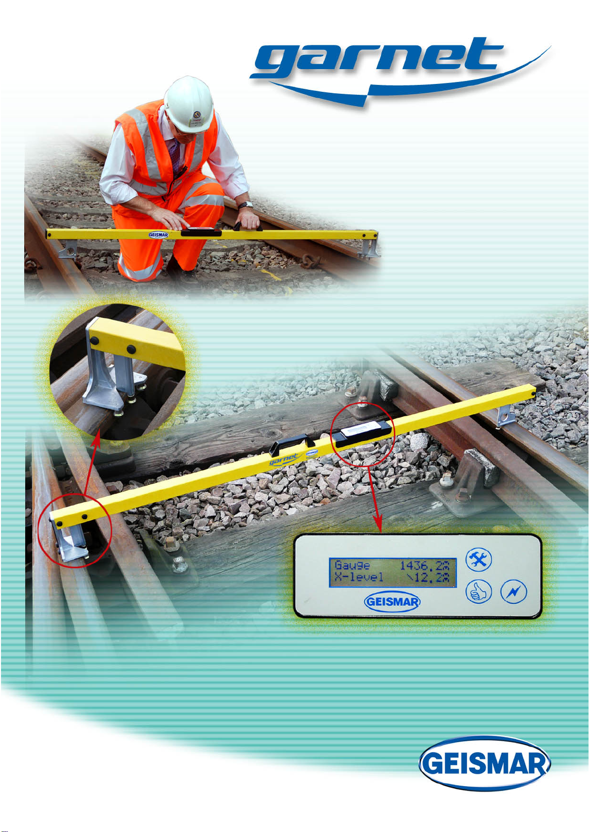
entire document is strictly forbidden without the prior written approval of GEISMAR. The manual is an essential part of the Garnet digital
track gauge and should be kept for the lifetime of the system. Any amendments or modifications to the manual provided by Geismar must
be kept with it and/or included in the manual itself.
DESCRIPTIVE MATTER AND ILLUSTRATIONS
Descriptive matter, illustrations, dimensions and weights issued by the company are typical and shall not be held as binding. The company
reserves the right to alter patterns and designs without notice.
LICENCE AND WARRANTY
The software/firmware, which accompanies this license, (the Software) is the property of Geismar or its licensors and is protected by
copyright law. While Geismar continues to own the Software, you will have certain rights to use the software after your acceptance of the
License. Your rights and obligations with respect to the use of this Software are as follows:
You may:
(i) Use one copy of the Software on a single gauge; if the Software is provided in more than one language version of the Media then
you are licensed for one language version per Software title contained on the media (you may not make copies of different
language versions) and you may not transfer such other versions to another person or allow another person to use such other
versions;
(ii) After written notice to Geismar, transfer the Software on a permanent basis to another person or entity, provided that you retain
no copies of the Software and the transferee agrees to the terms of this Agreement.
You may not:
(i) Copy the documentation that accompanies the Software
(ii) Sublicense, rent or lease any portion of the Software
(iii) Reverse engineer, decompile, disassemble, modify, translate, make any attempt to discover the source code of the Software, or
create derivative works from the Software; or
(iv) Use a previous version or copy of the Software after you have received a disk replacement set or an upgraded version as a
replacement of the prior version. All copies of the prior version must be destroyed.
Limited Warranty:
Geismar warrant that the media on which the Software is distributed is free from defects for a period of sixty (60) days from the date of
delivery of the Software to you. Your sole remedy in the event of a breach of this warranty will be that Geismar will, at its option, replace
any defective media returned within the warranty period. Geismar does not warrant that the Software will meet your requirements or that
the operation of the Software will be uninterrupted or that the Software will be error free.
THE ABOVE WARRANTY IS EXCLUSIVE AND IN LIEU OF ALL OTHER WARRANTIES, WHETHER EXPRESS OR IMPLIED,
INCLUDING THE IMPLIED WARRANTIES OF MERCHANTABILITY, FITNESS FOR A PARTICULAR PURPOSE AND NON-
INFRINGEMENT.
Disclaimer of Damages:
REGARDLESS OF WHETHER ANY REMEDY SET FORTH HEREIN FAILS OF ITS ESSENTIAL PURPOSE, IN NO EVENT WILL
GEISMAR BE LIABLE TO YOU FOR ANY SPECIAL, CONSEQUENTIAL, INDIRECT OR SIMILAR DAMAGES, INCLUDING
ANY LOST PROFITS OR LOST DATA ARISING OUT OF THE USE OR INABILITY TO USE THE SOFTWARE EVEN IF GEISMAR
HAS BEEN ADVISED OF THE POSSIBILITY OF SUCH DAMAGES.
SOME STATES DO NOT ALLOW THE LIMITATION OR EXCLUSION OF LIABILITY FOR INCIDENTAL OR CONSEQUENTIAL
DAMAGES SO THE ABOVE LIMITATION OR EXCLUSION MAY NOT APPLY TO YOU.
IN NO CASE SHALL GEISMARS’ LIABILITY EXCEED THE PURCHASE PRICE FOR THE SOFTWARE OR THE INSTRUMENT
ON WHICH THE SOFTWARE OPERATES WHICHEVER IS THE HIGHER AMOUNT.
The disclaimers and limitations set forth above will apply regardless of whether you accept the software.
General:
This Agreement will be governed by the laws of England. This Agreement may only be modified by a license addendum, which
accompanies this license, or by a written document, which has been signed by you and by Geismar. Should you have any questions
concerning this Agreement, please contact the sales agent through whom you purchased the gauge.
GAD04DOC820Ver9 - en.docx

Table of Contents
1Introduction..................................................................................................................................................5
1.1 Packing List...........................................................................................................................................5
1.2 Initial Instructions .................................................................................................................................5
2System Controls............................................................................................................................................6
2.1 Switching On.........................................................................................................................................6
2.2 Switching Off........................................................................................................................................6
2.3 Control Buttons.....................................................................................................................................6
2.4 Backlight...............................................................................................................................................7
2.5 Contextual Help Icons...........................................................................................................................7
2.6 DC Charging Socket .............................................................................................................................7
3Operating Instructions.................................................................................................................................8
3.1 Positioning the Garnet...........................................................................................................................8
3.2 Power On ..............................................................................................................................................8
3.3 Intuitive Measuring Mode Selection.....................................................................................................9
3.4 Measuring Modes..................................................................................................................................9
3.5 Acquiring Measurements ....................................................................................................................10
3.6 Twist Measurement.............................................................................................................................10
3.7 Cross-level Rezeroing Calibration ......................................................................................................10
4Software Menus..........................................................................................................................................11
4.1 Menu/Settings Description..................................................................................................................11
4.1.1 Battery............................................................................................................................................11
4.1.2 Cross-level Rezero .........................................................................................................................11
4.1.3 Language........................................................................................................................................11
4.1.4 Power.............................................................................................................................................11
4.1.5 Backlight........................................................................................................................................11
4.1.6 Measure Units................................................................................................................................12
4.1.7 Twist...............................................................................................................................................12
4.1.8 Groove............................................................................................................................................12
4.1.9 Groove Latch..................................................................................................................................12
4.1.10 Firmware Version ..........................................................................................................................12
4.1.11 Serial Number................................................................................................................................12
4.1.12 Calibration Date............................................................................................................................12
4.1.13 Exit Menu.......................................................................................................................................12
4.2 Cross-level Rezeroing Calibration ......................................................................................................12
5Charging the Batteries...............................................................................................................................14
6Maintenance of the Equipment.................................................................................................................15
6.1 Routine Inspection and Maintenance..................................................................................................15
6.2 Calibration...........................................................................................................................................15
7Trouble Shooting........................................................................................................................................16
8Technical Specification..............................................................................................................................17
8.1 Network Rail NR/L3/TRK/4900 Specific Models..............................................................................18
8.2 CE Certification ..................................................................................................................................19
GAD04DOC820Ver9 - en.docx

1 Introduction
The Geismar Garnet is a portable, lightweight, hand operated digital track gauge for measuring the
following seven track parameters:-
Gauge
Cross-level
Groove Clearance
Checkrail to opposite Running-rail
Running-rail to opposite Check-rail
Back-to-back Check-rail
Twist
1.1 Packing List
The Garnet is supplied with the following components. If any of these items are missing then contact
your local Geismar representative.
Track Gauge
Mains Battery Charger
Operating Manual
Calibration Certificate
1.2 Initial Instructions
The Garnet track gauge is fitted with an internal Ni-MH battery. Before the instrument is first used,
the battery must be fully charged using the procedure described in Chapter 5 of this manual.
Chapter
1
GAD04DOC820Ver9 - en.docx 5

2 System Controls
The Garnet has three buttons on its front panel as shown here. Many of the measuring modes are
selected automatically and an explanation of these modes and manually selected functions are detailed
in the following sections. The diagram below identifies these controls along with the other major
components found on the Garnet.
2.1 Switching On
The button marked () should be pressed for a period of approximately 2 seconds, this will run a
system test and then start the gauge operating.
2.2 Switching Off
Pressing both buttons (+
) simultaneously for 5 seconds will switch off the gauge. Alternatively,
if the auto ‘Power Off’ option has been enabled, then the gauge will automatically switch off after a
preset time of inactivity. This is detailed in the ‘Software Menus’ section of the manual..
2.3 Control Buttons
These two buttons are marked () and (
) and are used to operate the Garnet. Their functions
change depending on the current mode, but in most cases contextual help is provided to aid the user.
Chapter
2
Carry Handle
Groove Paddle
Measuring Feet
Charging Socket
Gauge Paddle Lock
Gauge Paddle
LCD Display & Controls
GAD04DOC820Ver9 - en.docx 6

2.4 Backlight
With the Garnet in measuring mode, pressing the () button will either will activate the LCD
backlight, for a pre-determined period, or toggle the backlight on and off. This is detailed in the
‘Software Menus’ section of the manual.
2.5 Contextual Help Icons
To assist the user in menu navigation, the Garnet makes use of on-screen contextual help icons. These
appear on the LCD alongside the relevant control button (or
) to remind the operator of their
function. Commonly used icons and an explanation of their meaning are listed below:-
() OK or Enter
() Scroll through option
() Next menu
2.6 DC Charging Socket
This socket is used for charging the battery and can be found on the underside of the Garnet. A battery
charger is provided with the Garnet and instructions on charging are covered in Chapter 5 of this
manual.
GAD04DOC820Ver9 - en.docx 7

3 Operating Instructions
In order to protect the Garnet from water and dust ingress, it must remain in its normal
upright measuring position, even when not in use!!
After use in wet weather, remove standing water from the Garnet using a clean, dry
cloth. Pay particular attention to the LCD/keypad recess and surrounding area.
Always remember that the Garnet Digital Gauge is an accurate measuring instrument
and not a hand tool. It is designed to operate in the railway environment but must at all
times be handled with care!!
During sudden changes in temperature, for example removing the Garnet from a warm
car on a cold day, the Garnet should be left to ‘stabilise’ before it is re-zeroed or used
for measurements!!
3.1 Positioning the Garnet
To maintain integrity of measurement, it is essential that the Garnet be placed on the track such that it
is absolutely perpendicular to the rails. This is achieved by ensuring BOTH measuring ‘feet’ found
on the Groove measuring side of the Garnet are in contact with the running face of the rail.
The Gauge paddle is spring-loaded outwards so it is necessary to retract this paddle before it can be
correctly positioned. Alternatively, and depending on what is being measured, this paddle can be
permanently retracted using the small catch found on the underside of the Garnet.
3.2 Power On
To switch on the Garnet, press the button marked () for
approximately 2 seconds. During the start-up process, the equipment
model, and the firmware version are displayed on the screen. After
approximately 10 seconds the initialisation message is replaced with the measuring screen.
If the remaining battery capacity is at 25% or less, a message is
briefly flashed up on the LCD during normal operation to alert the
operator. The frequency by which the message is displayed is
dependent on the remaining battery capacity, i.e. with 20% charge remaining, the battery level will be
displayed every 20 seconds, increasing to every 5 seconds with 5% charge remaining.
Chapter
3
GEISMAR GARNET
GAD04F000001CR
Battery!
GAD04DOC820Ver9 - en.docx 8

3.3 Intuitive Measuring Mode Selection
The Garnet is fitted with a high accuracy inclinometer, and two measuring ‘paddles’ enabling it to
measure up to seven track parameters. In order to maintain measurement integrity and improve ease
of use, the Garnet records the most extreme (max or min) value measured in the selected direction,
even if this is not the current value.
In the case of the Gauge paddle, a change in direction (and hence a change in measuring mode) will
only be acknowledged if the paddle movement exceeds 5mm in the opposite direction.
In the case of the Groove paddle, the maximum value will be stored until the paddle movement
exceeds 5mm in the opposite direction if Groove Latch is [Disabled], or if the user manually exits that
measuring mode by pressing the (
) button if Groove Latch is [Enabled]. See ‘Software Menus’.
3.4 Measuring Modes
The Garnet uses ‘intuitive measuring mode selection’ to determine which measurement(s) the
operator is attempting to make, based whether the paddles are being moved ‘In’ towards or ‘Out’
away from the track centre. The table below illustrates how the different measuring modes are
selected:-
Groove Paddle Enabled
Groove
Paddle
Gauge
Paddle Display Output Description
Out Out
Gauge 1436.4
X-level /152.1
m
m
m
m
Gauge
Cross-level including orientation
Out In
-
--1436.4
X-level /152.1
m
m
m
m
Running rail to opposite check rail
Cross-level including orientation
In Out
Groove 76.3
--/1400.1
m
m
m
m
Groove width or groove
Check rail to opposite running rail
In In
Groove 76.4
--/1372.1
m
m
m
m
Groove width or groove
Back-to-back check rail
Groove Paddle Disabled
In/Out Out
Gauge 1436.4
X-level /152.1
m
m
m
m
Gauge
Cross-level including orientation
In/Out In
Gauge ----
X-level /152.1
m
m
m
m
Error. Invalid Gauge paddle direction!
Cross-level including orientation
In the case of the Gauge paddle, a change in direction (and hence a change in measuring mode) will
only be acknowledged if the paddle movement exceeds 5mm in the opposite direction.
In the case of the Groove paddle, the maximum value will be stored until the user manually exits that
measuring mode by pressing the (
) button (if Groove Latch is on) or if the paddle movement
exceeds 5mm in the opposite direction (if Groove Latch is off).
GAD04DOC820Ver9 - en.docx 9

3.5 Acquiring Measurements
To further increase accuracy and repeatability, software averaging filters are implemented in the
Garnet. During the measuring process, these filters will take a few seconds to process the data and
therefore the display should only be read once the parameters have stabilised.
3.6 Twist Measurement
The Garnet has the ability to calculate Twist. This is achieved by
comparing the current Cross-levelvalue with the Cross-level value
previously stored by the operator.
The Twist base is undefined and is dependent on the distance separating the two Cross-level
measurements.
The Twist is displayed by pressing the
button when ‘Cross-level is displayed.
Pressing
again will store the current Cross-level value as the new Twist base reference and return
the Garnet to ’Cross-level’ measuring mode.
The first time the Twist screen is entered after a power-up will result in an invalid Twist
measurement being displayed as no base reference has yet been taken!
3.7 Cross-level Rezeroing Calibration
To maintain integrity of Cross-level and Twist measurements, the Garnet should regularly undergo a
Cross-level rezeroing calibration, as described in Chapter 4.2 of this manual. This should be
routinely performed on a daily basis and in the following circumstances:-
If the Garnet has had a severe knock
During sudden changes in temperature
If the temperature differs by more than 10°C since the last re-zeroing, the garnet will
automatically force the user to start a Cross-level Rezero.
Twist /36.4
m
m
GAD04DOC820Ver9 - en.docx 10

4 Software Menus
The Garnet has a structured menu system, enabling the operator to perform specific tasks and alter the
configuration of the instrument. The menu structure can only be entered before the unit is turned on.
To enter the menus, press and hold
, while turning on the unit by pressing for 2 seconds.
To assist the user in menu navigation, the Garnet makes use of on-screen contextual help icons. These
appear on the LCD alongside the relevant control button (or
) to remind the operator of their
function. Commonly used icons and an explanation of their meaning are listed below:-
() OK or Enter
() Scroll through option
() Next menu
4.1 Menu/Settings Description
Described below is the complete menu structure for the Garnet, a detailed explanation of each
menu/option can be found in the following few sections of this manual:-
4.1.1 Battery
Displays the remaining battery life, in percentage. When the
battery level falls below 25%, a message is briefly flashed up on
the LCD during normal operation to alert the operator. The
frequency by which the message is displayed is dependent on the remaining battery capacity, i.e.
with 20% charge remaining, the battery level will be displayed every 20 seconds, increasing to 5
seconds when the battery reaches 5%. During this period, the operator should consider charging
the Garnet.
Note that the battery status value is only an indicator and not an exact figure. If the Garnet is
charged from flat for only 10 minutes, the indicator may display 100%, however, this will rapidly
deplete if removed from charge.
4.1.2 Cross-level Rezero
See Section 4.2 of this operating manual.
4.1.3 Language
Sets the operating language of the Garnet
4.1.4 Power
In Auto-off mode, the Garnet automatically switches itself off after 10 miniuts, pressing either of
the control buttons will reset the timer. In Manual mode, the Garnet will remain on until the
operator manually switches it off, by pressing the (+
) buttons.
4.1.5 Backlight
In Auto-off, the backlight can be switched on for 10 seconds, by pressing . When the backlight,
is set to manual then pressing will toggle the backlight on and off. Prolonged use of the
backlight will have a detrimental effect on the battery life!
Chapter
4
Battery!
GAD04DOC820Ver9 - en.docx 11

4.1.6 Measure Units
Selects whether the Garnet displays measurements in milimeters or inches. When set to
milimeters, temprature is displayed 8C, when set to Imperial, temprature is displayed 8F.
4.1.7 Twist
Enables or disables the ‘Twist’ parameter. If enabled, the Twist parameter can be seleced by
pressing the
button while in Gauge mode.
4.1.8 Groove
Enables or disables the Groove measuring paddle. If disabled, only Cross-level, Gauge and Twist
can be measured, thus simplifying the operation of the Garnet.
4.1.9 Groove Latch
Enables or disables the Groove latch mechanism. If set, the maximum Groove value will be stored
until the user manually exits that measuring mode by pressing the
button. If disabled, the
Groove value will be reset if the paddle movement exceeds 5mm in the opposite direction.
4.1.10 Firmware Version
Displays the current firmware version, the operator cannot change this value. Please contact your
Geismar representative regarding firmware updates.
4.1.11 Serial Number
Displays the serial number, the operator cannot change these values. Please quote this serial
number when you contact your Geismar representative.
4.1.12 Calibration Date
Displays the date when last calibrated, if more than 12 months has elapsed, then the unit should be
returned to your local Geismar representative for re-calibration.
4.1.13 Exit Menu
Select to exit the menu, or select, then menu will loop around to the start (Battery).
4.2 Cross-level Rezeroing Calibration
To maintain integrity of Cross-level and Twist measurements, the Garnet should regularly undergo a
Cross-level Rezeroing calibration. This should be routinely performed and in the following
circumstances:-
If the Garnet has had a severe knock
During sudden changes in temperature
If the temperature differs by more than 10°C since the last re-zeroing (warning given)
In the event of sudden changes in temperature, for example removing the Garnet from a warm
car on a cold day, the Garnet should be left to ‘stabilise’ before it is re-zeroed or used for
measurements.
The ‘Cross-level Rezeroing Calibration’ should be performed on a section of track clear from
welds, joints and any other irregularities that may prevent the Garnet from sitting firmly on the
rails. For best results, the track Cross-level should be close to zero (<30mm).
During each re-zeroing process, the internal temperature is stored by the Garnet. During operation, the
current temperature is constantly monitored and compared to this stored value. If it differs by more
than 10°C then the user is forced to perform a Cross-level Rezero!!The Cross-level Rezeroing
Calibration function can also be found within the front-end user menu and is accessed by pressing the
GAD04DOC820Ver9 - en.docx 12

button, while turning on the unit with the button .
Scroll through the menu options using the () button until the
following message is displayed, then select by pressing the
button.
X-level
Rezero?
When prompted with the following message, place the Garnet
firmly and squarely on the track, making a note of its exact
location.
Measure
A--==--B
Press the button to begin the calibration process. During the
measuring process a ‘thermometer’ bar graphs indicates the
progress. It is essential that the Garnet is not touched during this
measuring process
Processing…
When prompted with the following message, turn the Garnet
around so the Gauge paddle is now on the opposite rail but at
EXACTLY the same location on the track
Rotate 180?
B--==--A
Ensure that the Garnet is firmly and squarely positioned and press
the button to continue the calibration process. During the
measuring process a ‘thermometer’ bar graphs indicates the
progress. It is essential the Garnet is not touched during this
measuring process.
Processing…
Once the calibration process is complete, the following message
will be displayed. If Cross-level Rezeroing was initiated manually
by selecting from within the ‘user menu’ then the number displayed
represents the ABSOLUTE offset for Cross-level. If however the
rezeroing was initialised automatically (due to a change in
temperature) then the number displayed represents the ‘adjustment’
made to the previously stored value, thus giving an indication of the
previous offset error.
Calibrated:
+0.4
m
m
At the end of the Cross-level Rezeroing process the final value is
checked to ensure it is within certain criteria. If these criteria are
not met then the calibration is aborted and the following message is
displayed. In this instance, the user should attempt to re-zero again
before using the Garnet.
Failed!
GAD04DOC820Ver9 - en.docx 13

5 Charging the Batteries
The Garnet has an internal 7.2v Ni-MH rechargeable battery pack that must not be
removed by the operator. The maximum autonomy of the battery pack for the Garnet is
approximately 200 hours use, actual autonomy will be dependent upon operational
process and Bluetooth usage (with PDA)
It is strongly recommended that the battery is never charged if the capacity showing on the
control panel (section 3.2) is more than 4 bars. This will correspond to a minimum of 20
hours use and so the Garnet can be safely used for one shift and then recharged.
Displaying the battery status is described in section 4.1 above.
The following procedure should be used when charging the Garnet.
1) Position the Garnet on a flat surface ensuring it is clean and dry.
2) Insert the charger DC jack into the socket found on the underside of the Garnet and
then plug the charger unit into the mains supply. The charger has an input operating
voltage range of
100VAC to 240VAC, 50-60 Hz.
3) The unit will take approximately 15 hours to charge, assuming a completely
uncharged condition.
4) Once the battery is charged, disconnect the charger from the mains supply and
remove the charging plug from the instrument. The Garnet is now ready for use.
The instrument should never be left charging for more than 24 hours as this will cause
long-term damage to the batteries. If the Garnet is left unused, the batteries will discharge in
about 5 months, so it is recommended that the Garnet be recharged approximately every 4
months, even when not in use.
Under normal operating conditions it is not necessary to ‘cycle’ (discharge and charge) the
Garnet batteries, however if the autonomy of the instrument is reduced, a complete discharge
cycle may help restore the battery capacity. This is achieved by setting the ‘Power’ mode to
‘Manual’ (see section 4.1.4), restarting the Garnet and leaving it on for 24 hours (or until it
switches itself off). The unit should then be placed on charge for no more than 24 hours.
Chapter
5
GAD04DOC820Ver9 - en.docx 14

6 Maintenance of the Equipment
Provided the Garnet Digital gauge is handled with care and the operating instructions are adhered to,
only minimum maintenance is required.
Always remember that the Garnet digital gauge is an accurate measuring instrument and not a
hand tool. It is designed to operate in the railway environment but must at all times be handled
with care!!
Note that the Garnet must not be oiled as this may damage the instrument.
6.1 Routine Inspection and Maintenance
The Garnet should be cleaned after use and any grease that has accumulated should be
removed.
If the Garnet has been used in rain, it should be dried with a clean cloth prior to storage.
Ensure that the internal battery is regularly re-charged (See chapter 5) in order to prevent
long-term damage.
Regularly check for any signs of damage or misuse.
Regularly check for excessive play in the measuring paddles.
Regularly check that the paddle movement is smooth and free from glitches.
6.2 Calibration
Spot checks for calibration accuracy should be carried out as part of the routine maintenance. This is
achieved by taking measurements with the Garnet at specific points where the geometry is already
known. If a fault is suspected then the instrument must be returned immediately to your local
Geismar representative for full calibration or repair.
It is recommended that the Garnet be returned to your local Geismar representative for calibration
every 12 months or in accordance to your companies QA policy.
Chapter
6
GAD04DOC820Ver9 - en.docx 15

7 Trouble Shooting
Listed below is a trouble-shooting guide for the Garnet. If after trying the solutions described below
the problem still exist, contact your Geismar representative.
The Garnet doesn’t switch on:-
Hold the power on key () down for several seconds. If the display shows no changes or
flickering, then charge the battery. See also ‘The Garnet Freezes’ troubleshooting guide below.
The Garnet only lasts a few hours between charges:-
Check that the Backlight timer is not set to manual as having the backlight on continuously will
significantly reduce the battery life of the Garnet. ‘Auto Off’ is the recommended setting.
The Garnet displays ‘ErrorTrap 7’ on the LCD:-
Re-zero the Garnet using the procedure described in Section 4 of this manual. Please report the
error, along with the serial number and firmware version of your unit (displayed on the LCD at
start-up) to ‘garnet@geismar.co.uk’.
The Garnet has a Cross-level offset error:-
Rezero the Garnet using the procedure described in Section 4 of this manual.
The Garnet Freezes:-
Reset the Garnet by holding down the (+
) buttons for 10 seconds and then release. Once
switched off, re-initialise by pressing the () button. If the Garnet does not switch on then it
may be necessary to first recharge the battery.
The Garnet does not measure Twist or Groove clearances:-
Ensure that the Groove measuring mode is ‘Enabled’ in the setup menu.
Geismar has a commitment to constant improvement of its measuring equipment. Should
the Garnet report an error on the LCD screen then please report this error, along with the
serial number and firmware version of your unit (displayed on the LCD at start-up) to
‘garnet@geismar.co.uk’. It is possible your unit may require a firmware update.
Chapter
7
GAD04DOC820Ver9 - en.docx 16

8 Technical Specification
Performance
Nominal Track Gauge Model
Parameter 1000 1435 1600 Accuracy Resolution
Gauge (mm) -50 to +50 -50 to +50 -50 to +50 ±1.0 ±0.1
Cross-level (mm) ± 150 ± 200 ± 200 ±1.0 ±0.1
Groove gap (mm) 25 - 120 25 - 120 25 - 120 ±1.0 ±0.1
* Check/Running Rail (mm) 830 - 1025 1265 - 1460 1430 - 1625 ±1.0 ±0.1
* Check/Check Rail (mm) 815 - 1010 1250 - 1445 1415 - 1610 ±1.0 ±0.1
* Measuring ranges are absolute maximums. Actual range will vary, and maybe less, depending on
measurement being taken.
Gauge Thrust Bearings (contact point)
Shape
Contact point
Cylindrical 0-14mm below rail top (Standard A)
Shouldered
13-16mm below rail top (Standard B)
11-14mm below rail top (Standard C)
Batteries Integral rechargeable Ni-MH
Autonomy Nominal 200 hours without backlight
Charging Via external universal input charging unit (110-220VAC 50/60 Hz)
Charging Time 15 hours for complete charge
Weight 3 Kg.
Size Standard 1000 1250mm long x 175mm high x 100mm wide
Standard 1435 1700mm long x 175mm high x 100mm wide
Standard 1600 1850mm long x 175mm high x 100mm wide
Chapter
8
GAD04DOC820Ver9 - en.docx 17

8.1 Network Rail NR/L3/TRK/4900 Specific Models
Models (deviation from standard technical specification)
Network Rail Track Inspection Digital Gauge TYPE 2 (incorporates shouldered thrusts)
-Geismar Garnet P8 (single piece unit)
-Geismar Garnet P8-T (two-piece unit)
Parameter Range Accuracy Resolution
Gauge (mm) 1410 to 1490 ±1.0 ±0.1
Groove gap (mm) 25 to 125 ±1.0 ±0.1
Network Rail Layout Inspection Digital Gauge TYPE 3 (incorporates cylindrical thrusts)
-Geismar Garnet P8-P (single piece unit)
-Geismar Garnet P8-P-T (two-piece unit)
Parameter Range Accuracy Resolution
Gauge (mm) 1410 to 1490 ±0.5 ±0.1
Groove gap (mm) 25 to 125 ±1.0 ±0.1
Electrical Insulation
The Garnet digital track gauge comprises of a yellow GRP body which has an electrical
insulation resistance greater than 800 GΩ per cm. It does not interfere with track signals and
is compatible for use in Live 3rd and 4th rail areas. It complies with NR/L3/TRK/4900.
GAD04DOC820Ver9 - en.docx 18

8.2 CE Certification
Declaration of Conformity
Design Authority : Geismar (UK) Limited,
Salthouse Road,
Brackmills Industrial Estate,
Northampton,
England, NN4 7EX
Telephone : 01604-769191
Fax : 01604-763154
E-Mail : Sales@Geismar.co.uk
Description : GARNET Digital Track Gauge
Weight : 3.00kg
Noise Level (dBA) : n/a
Vibration Level (m/s²) : < 1
This machine conforms to
The Supply of Machinery (Safety) Regulations 1992
Rail Safety Group Standard GM/RT 1310
EMC Regulations for Railway Applications EN50121
The Low Voltage Directive
Supplied By Societe L. Geismar
N. MacCuaig
UK Development Manager
Attention: Any modification to this gauge without the prior written agreement of the Manufacturer
will invalidate this certificate
GAD04DOC820Ver9 - en.docx 19
This manual suits for next models
2
Table of contents
Other GEISMAR Measuring Instrument manuals