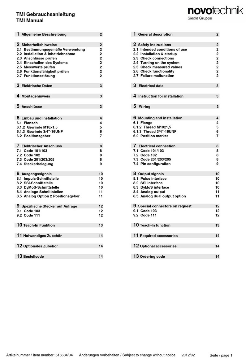
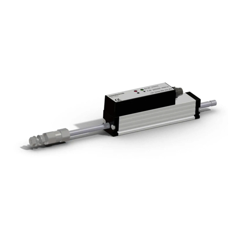
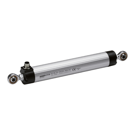
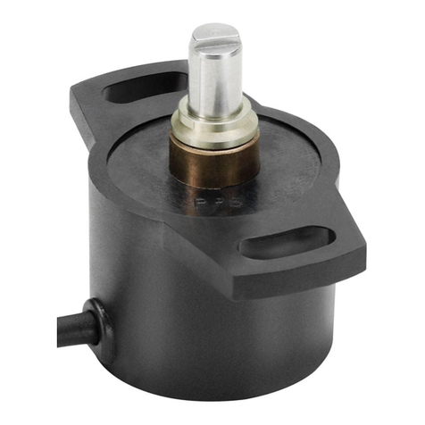
manuals.online logo
Brands
  1. Home
  2. •
  3. Brands
  4. •
  5. novotechnik
  6. •
  7. Transducer
  8. •
  9. novotechnik TEX Series User manual

novotechnik TEX Series User manual

TEX Gebrauchsanleitung
TEX User manual
Artikelnummer / Item number: 517142/07 Änderungen vorbehalten / Subject to change without notice 2013/03
1Allgemeine Beschreibung
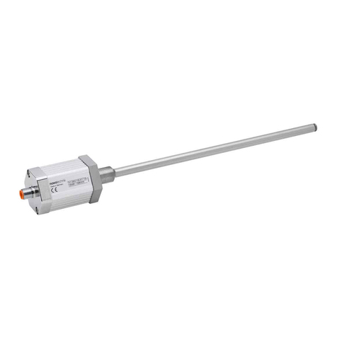
Die Baureihe TEX ist ein potentiometrischer Wegaufnehmer für
direkte, genaue und absolute Messung von Wegen bzw. Längen
in der Steuerungs-, Regelungs- und Messtechnik.
2Sicherheitshinweise
Unsere Produkte sind regelmäßig nicht für Luft- und
Raumfahrtanwendungen zugelassen und dürfen nicht in
kerntechnischen oder militärischen, insbesondere ABC-relevanten
Applikationen verwendet werden.
Weitere Informationen s. unsere AGBs.
2.1 Bestimmungsgemäße Verwendung
Der Wegaufnehmer wird zu seiner Verwendung in eine Maschine
oder Anlage eingebaut. Er bildet zusammen mit einer Steuerung
(z.B. SPS) ein Wegmesssystem und darf auch nur für diese
Aufgabe eingesetzt werden.
Unbefugte Eingriffe, nicht bestimmungsgemäße Verwendung oder
Nichtbeachtung der Montagehinweise führen zum Verlust von
Gewährleistungs-, Garantie- und Haftungsansprüchen.
2.2 Installation & Inbetriebnahme
Der Wegaufnehmer ist nur von Fachpersonal und unter
Berücksichtigung aller geltenden Sicherheitsbestimmungen in
Betrieb zu nehmen. Alle Maßnahmen zum Schutz von Personen
und Sachen bei einem Defekt des Wegaufnehmers müssen vor
der Inbetriebnahme getroffen werden.
Schubstange nicht einfetten!
Durch starke Temperaturschwankungen (Kondensation),
kann sich Feuchtigkeit im Wegaufnehmer bilden, und die
Funktion des Wegaufnehmers beeinträchtigen.
3Elektrische Anschlüsse
Die Versorgungsspannung darf nur ausschließlich an die dafür
vorgesehenen Anschlüsse verbunden werden. Die Abschirmung
des Anschlusskabels ist an Masse anzuschließen. Falsche
Verbindungen und Überspannung können zur Beschädigung der
Bauteile führen. Prüfen Sie deshalb vor dem Einschalten die
Anschlüsse immer sorgfältig.
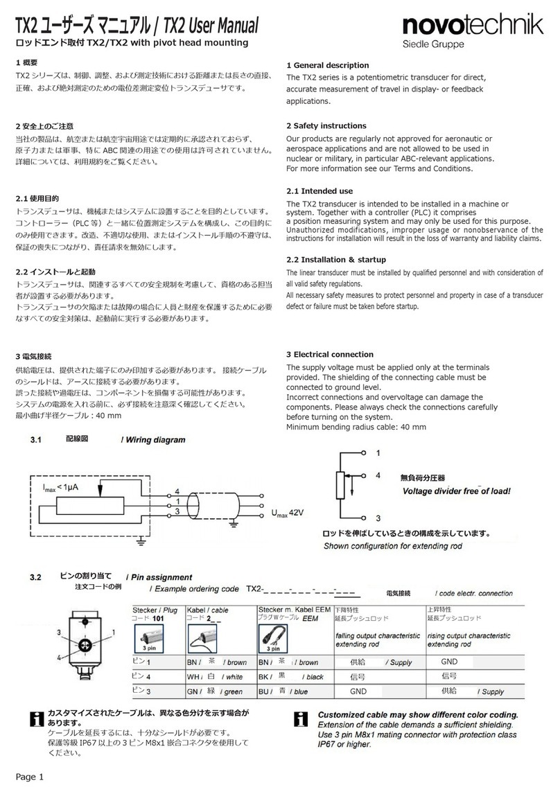
3.1 Anschlussschema / Wiring diagram
1General description
The TEX series is a potentiometric transducer for direct,
accurate measurement of travel in display- or feedback
applications.
2Safety instructions
Our products are regularly not approved for aeronautic or
aerospace applications and are not allowed to be used in
nuclear or military, in particular ABC-relevant applications.
For more information see our Terms and Conditions.
2.1 Intended use
This transducer is intended to be installed in a machine or
system. Together with a controller (e.g. PLC) it comprises a
position measuring system and may only be used for this
purpose.
Unauthorized modifications, improper usage or non-observance
of the instructions for installation will result in the loss of
warranty and liability claims.
2.2 Installation & startup
The transducer must be installed by qualified personnel and
with consideration of all valid safety regulations.
All necessary safety measures to protect personnel and
property in case of a transducer defect or failure must be taken
before startup.
Do not lubricate the actuating rod!
Strong temperature variations (condensation) can
deposit humidity in the position transducer and impair
the function of the linear transducer.
3Electrical connections
The supply voltage must be applied only at the terminals
provided. The shielding of the connecting cable must be
connected to ground level.
Incorrect connections and overvoltage can damage the
components. Please always check the connections carefully
before turning on the system.
1
34
4
1
3Umax 42V
Imax < 1µA
3.2 Anschlussbelegung / Terminal assignment
3
4
1
Lastfreier Spannungsteiler!
Voltage divider free of load!
Konfektionierte Kabel können abweichende Farbbelegung aufweisen.
Bei Verlängerung des Kabels ist auf ausreichende Schirmdämpfung zu achten.
Customized cable may show different color coding.
Extension of cable demands a sufficient shielding.
Stecker / Plug
Code 101
Kabel / cable
Code 2__, 3__
Kabel mit Stecker /
Cable with connector
EEM 33-64/-66/-68
EEM 33-65/-67/-69
fallende Kennlinie /
falling characteristic
steigende Kennlinie /
rising characteristic
PIN 1 BN / braun / brown BN / braun / brown Versorgung / Supply Masse / GND
PIN 4 WH / weiß / white BK / schwarz / black Signal Signal
PIN 3 GN / grün / green BU / blau / blue Masse / GND Versorgung / Supply
Dargestellte Belegung für ausfahrende Schubstange.
Shown configuration for extended position of the actuating rod.
Seite / page 1
TEX Gebrauchsanleitung
TEX User manual
Artikelnummer / Item number: 517142/07 Änderungen vorbehalten / Subject to change without notice 2013/03
Zentralbefestigung / Central mounting
Montage bei Zentralbefestigung mit Mutter M10
(nicht im Lieferumfang enthalten).
Assembly with central mounting: use nut M10
(not included in delivery).
4Ausführungen / Models
4.1 TEX mit Schubstange / TEX with actuating rod
Der Betrieb des Sensors in Eigenresonanz ist zu vermeiden, dies kann zu Beschädigungen der Mechanik führen.
Take care to avoid natural resonance of the sensor, this can lead to damages of the sensor mechanics.
max. 150 Ncm
max. 180 Ncm
4.2 TEX mit Rückstellfeder / TEX with return spring
Befestigungsarten siehe 4.1 / methods of mounting see 4.1
4.3 TEX mit Gelenkkopfmontage / TEX with pivot head mounting
Empfohlener Einbau
horizontal: Stecker nach unten
vertikal: Schubstange nach unten
Recommended mounting
horizontal: plug down
vertical: actuating rod down
Die internen Endanschläge sind mechanisch nicht
belastbar. Ein unkontrolliertes Rückfedern der Schubstange
kann zur Beschädigung führen!
The internal end stop is not mechanical resistant.
A uncontrolled release of the spring at the actuating rod can
lead to damage!
5 Zubehör
PUR-Kabel mit 3-pol Kupplungsdose, M8x1, 3x0,34 mm²,
ungeschirmt:
• 2 m Länge, EEM 33-64 (Art.Nr. 005617),
• 5 m Länge, EEM 33-66 (Art.Nr. 005619),
• 10 m Länge, EEM 33-68 (Art.Nr. 005643);
PUR-Kabel mit 3-pol Winkeldose, M8x1, 3x0,34 mm²,
ungeschirmt:
• 2 m Länge, EEM 33-65 (Art.Nr. 005618),
• 5 m Länge, EEM 33-67 (Art.Nr. 005620),
• 10 m Länge, EEM 33-69 (Art.Nr. 005644);
• Gelenkkopf, mit Innengewinde M5, Z-G01 (Art.Nr. 056014);
• Kugelkupplung Z301-M5/M5, (Art.Nr. 058002);
5 Accessories (order separately)
PUR-cable with 3-pin female connector, M8x1, 3x0,34 mm²,
unshielded:
•2 m length, EEM 33-64 (P/N 005617),
•5 m length, EEM 33-66 (P/N 005619),
•10 m length, EEM 33-68 (P/N 005643);
PUR-cable with 3-pin female angled connector, M8x1,
3x0,34 mm², unshielded:
•2 m length, EEM 33-65 (P/N 005618),
•5 m length, EEM 33-67 (P/N 005620),
•10 m length, EEM 33-69 (P/N 005644);
•Pivot head, internal thread M5, Z-G01, (P/N 056014);
•Ball coupling Z301-M5/M5, (P/N 058002);
Seite / page 2
Die Montage des Sensor erfolgt an der Zentralbefestigung
mit einem Anzugsdrehmoment am Bund von max. 5 Nm.
The mounting of the sensor takes place at the center
mounting with a tightening torque on the collar of max. 5 Nm.
Spannklammernbefestigung / Clamp mounting
Im Lieferumfang enthalten: 2x Spannklammern inkl.
4x Zylinderschrauben M5x20.
Included in delivery: 2x clamps incl. 4x cylinder head screws
M5x20.
.
max. 5 Nm

Other novotechnik Transducer manuals

novotechnik TH1 Series User manual

novotechnik

novotechnik TH1 Series User manual

novotechnik LWX Series User manual

novotechnik

novotechnik LWX Series User manual

novotechnik TIM Series User manual

novotechnik

novotechnik TIM Series User manual

novotechnik PTP Series User manual

novotechnik

novotechnik PTP Series User manual

novotechnik RFC-4800 CAN User manual

novotechnik

novotechnik RFC-4800 CAN User manual

novotechnik TM1 Series User manual

novotechnik

novotechnik TM1 Series User manual

novotechnik TLM 102 Series User manual

novotechnik

novotechnik TLM 102 Series User manual

novotechnik LS1 Series User manual

novotechnik

novotechnik LS1 Series User manual

novotechnik TM1 Series User manual

novotechnik

novotechnik TM1 Series User manual

novotechnik TH1 CANopen User manual

novotechnik

novotechnik TH1 CANopen User manual

novotechnik RSC-2800 User manual

novotechnik

novotechnik RSC-2800 User manual

novotechnik TH1 Series User manual

novotechnik

novotechnik TH1 Series User manual

novotechnik RSM-2800 User manual

novotechnik

novotechnik RSM-2800 User manual

novotechnik T Series User manual

novotechnik

novotechnik T Series User manual

novotechnik TMI Series User manual

novotechnik

novotechnik TMI Series User manual

novotechnik TIM Series User manual

novotechnik

novotechnik TIM Series User manual

novotechnik Z-TF1-PO1 User manual

novotechnik

novotechnik Z-TF1-PO1 User manual

novotechnik TX2 Series User manual

novotechnik

novotechnik TX2 Series User manual

novotechnik LWG Series User manual

novotechnik

novotechnik LWG Series User manual

novotechnik RSM-2800 User manual

novotechnik

novotechnik RSM-2800 User manual

novotechnik TLH User manual

novotechnik

novotechnik TLH User manual

novotechnik TP1 Series User manual

novotechnik

novotechnik TP1 Series User manual

Popular Transducer manuals by other brands

Eaton IQ 100 series quick start guide

Eaton

Eaton IQ 100 series quick start guide

HBM U9C Series Mounting instructions

HBM

HBM U9C Series Mounting instructions

HBM TB2 Mounting instructions

HBM

HBM TB2 Mounting instructions

MG 17CE instruction manual

MG

MG 17CE instruction manual

FIAMA MAT2 User manual and maintenance

FIAMA

FIAMA MAT2 User manual and maintenance

RS PRO ICA32N instruction manual

RS PRO

RS PRO ICA32N instruction manual

Hontzsch UVA operating instructions

Hontzsch

Hontzsch UVA operating instructions

Simrad 50-200 COMBI C -  REV D installation manual

Simrad

Simrad 50-200 COMBI C - REV D installation manual

Fairchild T6100 Installation, operation and maintenance instructions

Fairchild

Fairchild T6100 Installation, operation and maintenance instructions

MAMAC SYSTEMS EP-313 installation instructions

MAMAC SYSTEMS

MAMAC SYSTEMS EP-313 installation instructions

Fluke Q-RPT instruction sheet

Fluke

Fluke Q-RPT instruction sheet

KEPO KPM-G1201A9-K9096 manual

KEPO

KEPO KPM-G1201A9-K9096 manual

NITRA PNEUMATICS NCP1 Series Installation, operation and maintenance instructions

NITRA PNEUMATICS

NITRA PNEUMATICS NCP1 Series Installation, operation and maintenance instructions

WIKA CPT6010 operating instructions

WIKA

WIKA CPT6010 operating instructions

Balluff BTL7-A501-M-P-S32/KA Series instruction manual

Balluff

Balluff BTL7-A501-M-P-S32/KA Series instruction manual

Omega PX276 instruction sheet

Omega

Omega PX276 instruction sheet

WIKA CPT6020 operating instructions

WIKA

WIKA CPT6020 operating instructions

MG LTRPN instruction manual

MG

MG LTRPN instruction manual

manuals.online logo
manuals.online logoBrands
  • About & Mission
  • Contact us
  • Privacy Policy
  • Terms and Conditions

Copyright 2025 Manuals.Online. All Rights Reserved.