manuals.online logo
Brands
  1. Home
  2. •
  3. Brands
  4. •
  5. M-system
  6. •
  7. Transducer
  8. •
  9. M-system M5XWTU User manual

M-system M5XWTU User manual

5-2-55, Minamitsumori, Nishinari-ku, Osaka 557-0063 JAPAN
Phone: +81(6)6659-8201 Fax: +81(6)6659-8510 E-mail: info@m-system.co.jp
EM-2768-A Rev.4 P. 1 / 4
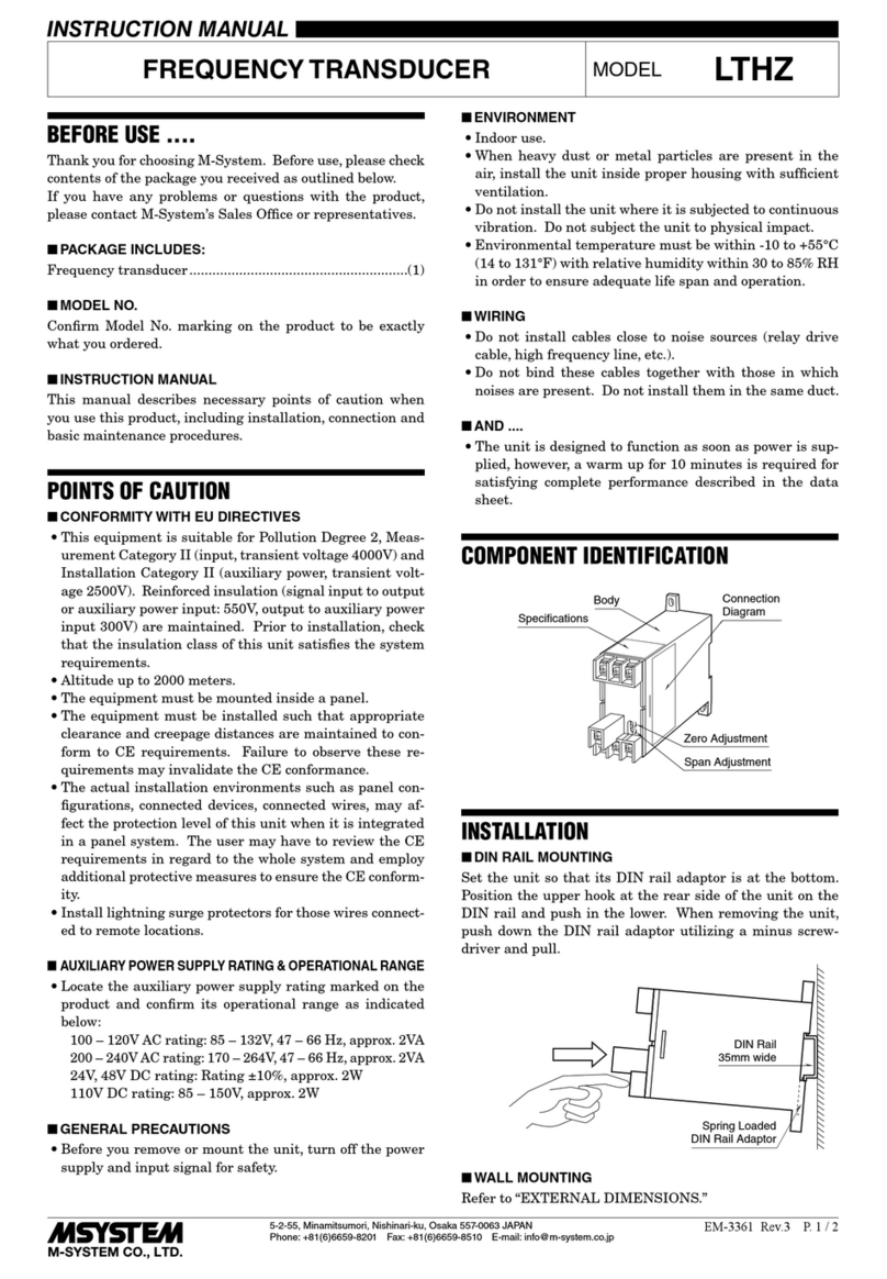
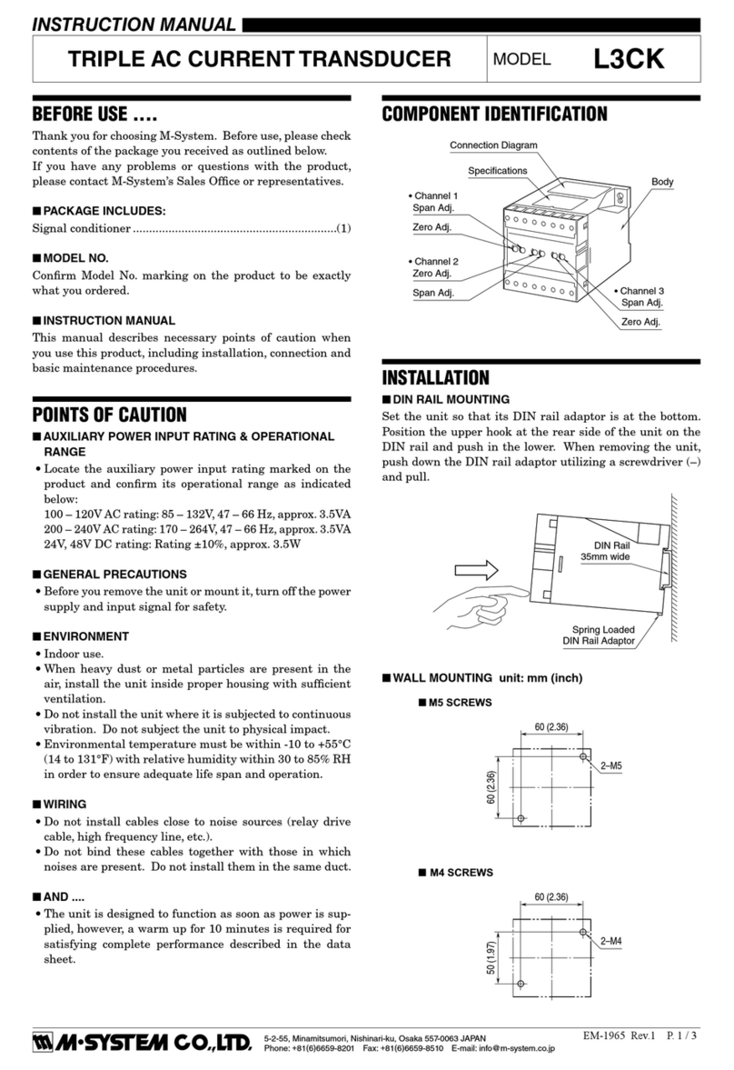
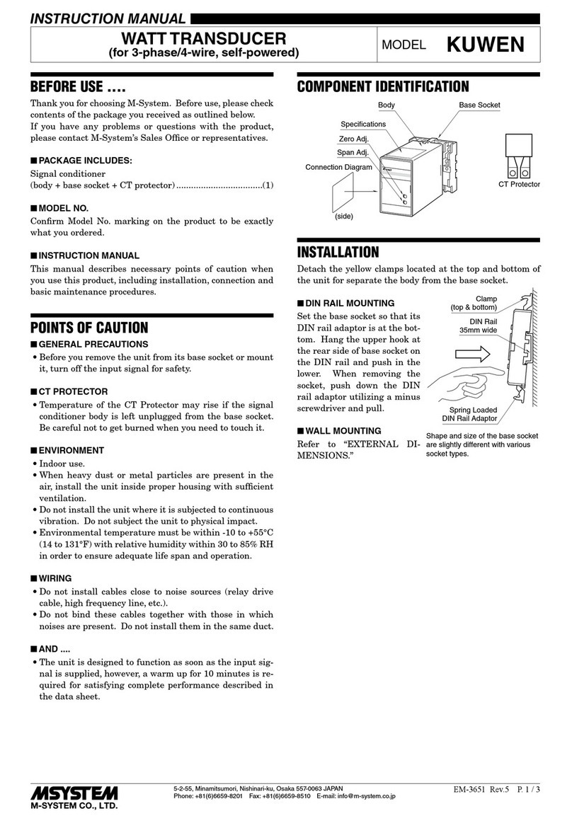
INSTRUCTION MANUAL
MULTI POWER TRANSDUCER
(self-powered, PC programmable) MODEL M5XWTU
BEFORE USE ....
Thank you for choosing M-System. Before use, please check
contents of the package you received as outlined below.
If you have any problems or questions with the product,
please contact M-System’s Sales Office or representatives.
■PACKAGE INCLUDES:
Signal conditioner ...............................................................(1)
■MODEL NO.
Confirm Model No. marking on the product to be exactly
what you ordered.
■INSTRUCTION MANUAL
This manual describes necessary points of caution when
you use this product, including installation, connection and
basic maintenance procedures.
The M5XWTU is programmable using the PC Configurator
Software. For detailed information on the PC configuration,
refer to the PMCFG users manual. The PMCFG PC Con-
figurator Software is downloadable at M-System’s web site:
https://www.m-system.co.jp
Refer to EM-2768-B for the use of Modbus.
POINTS OF CAUTION
■AUXILIARY POWER
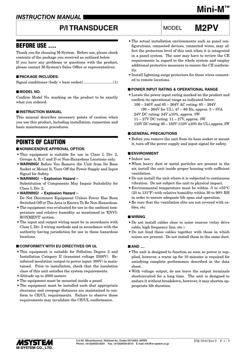
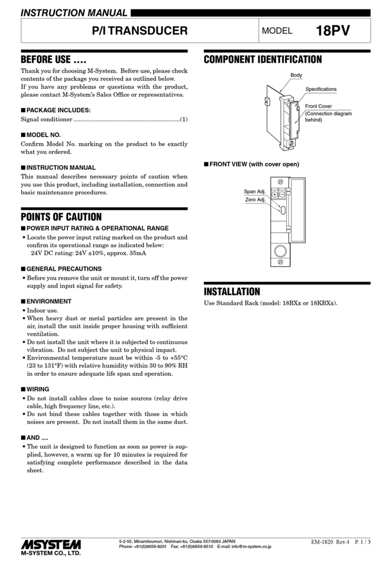
• M5XWTU does not have input terminals for auxiliary
power. The power for operation is generated from the
voltage input terminals P1 - P2, with consuming 3 VA be-
tween these terminals.
■GENERAL PRECAUTIONS
• Before you remove the unit or mount it, turn off the input
signal for safety.
■ENVIRONMENT
• Indoor use.
• When heavy dust or metal particles are present in the
air, install the unit inside proper housing with sufficient
ventilation.
• Do not install the unit where it is subjected to continuous
vibration. Do not subject the unit to physical impact.
• Environmental temperature must be within -20 to +65°C
(-4 to +149°F) with relative humidity within 30 to 90%
RH in order to ensure adequate life span and operation.
■WIRING
• Do not install cables close to noise sources (relay drive
cable, high frequency line, etc.).
• Do not bind these cables together with those in which
noises are present. Do not install them in the same duct.
• Install lightning surge protectors for those wires connect-
ed to remote locations.
■AND ....
• The unit is designed to function as soon as power is sup-
plied, however, a warm up for 10 minutes is required for
satisfying complete performance described in the data
sheet.
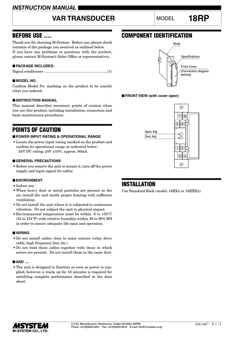
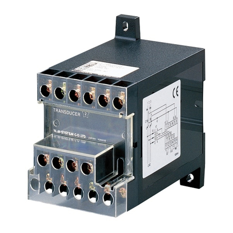
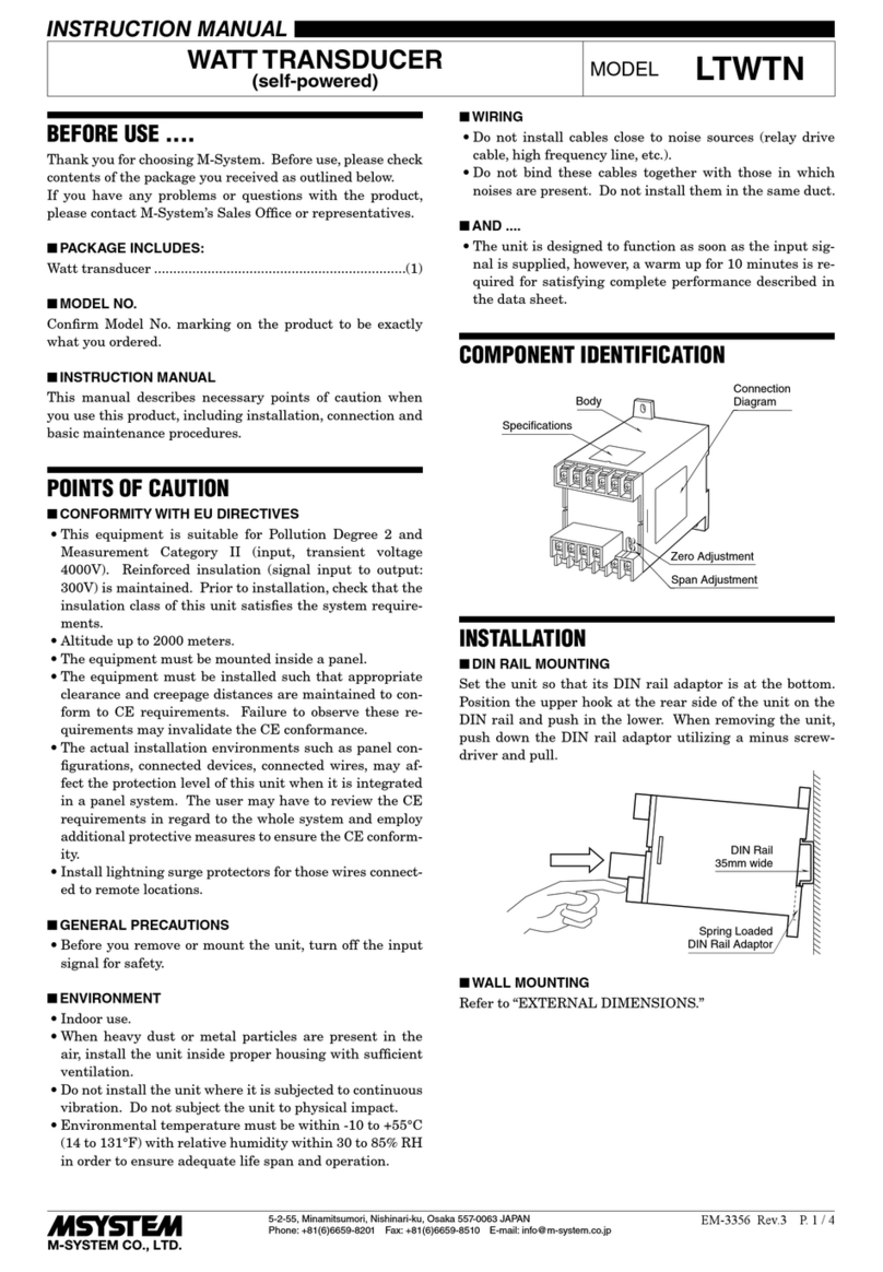
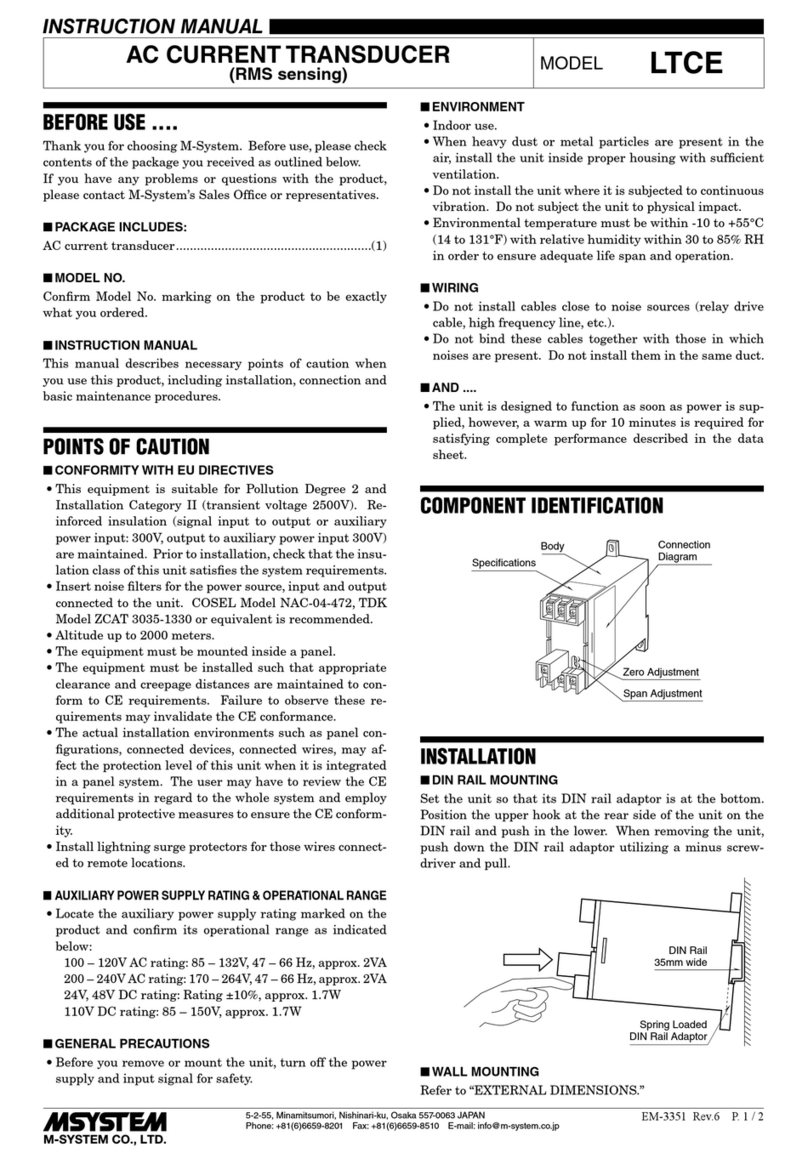
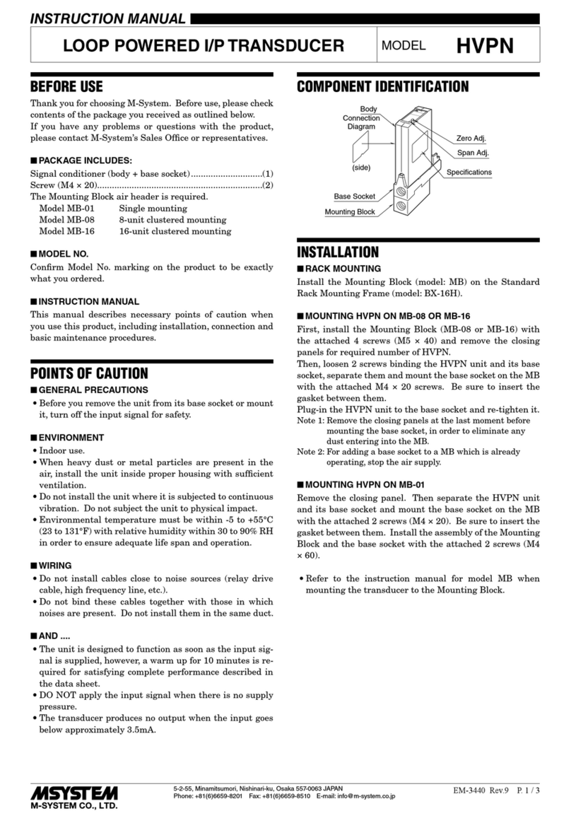
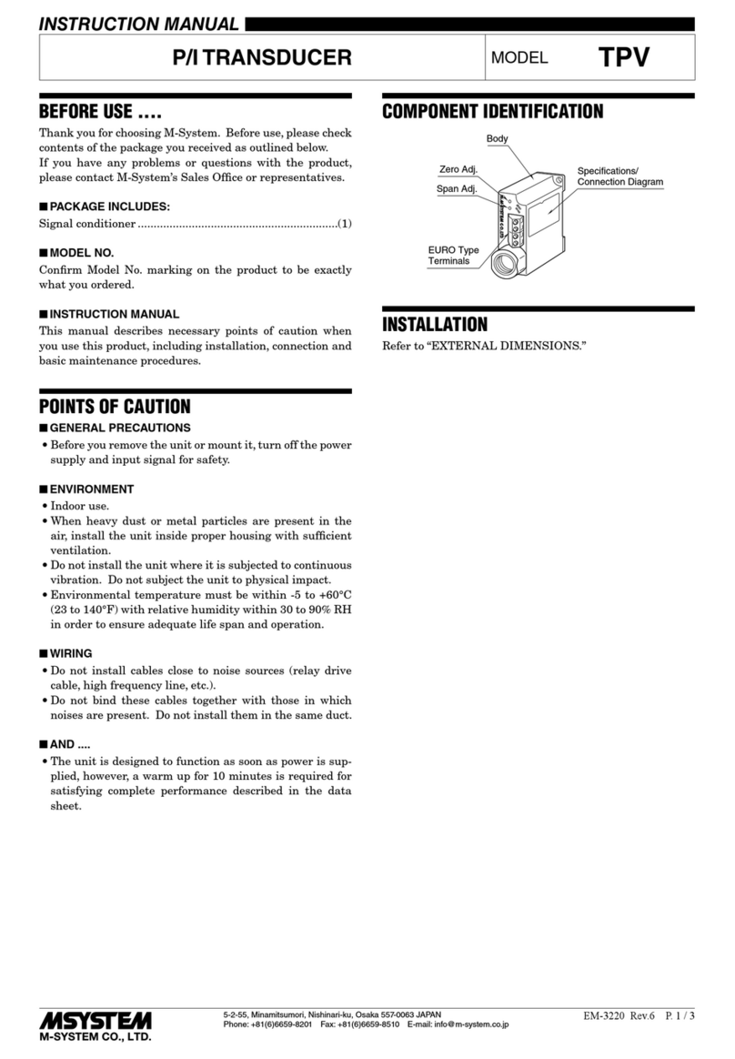
COMPONENT IDENTIFICATION
TerminalCover
PowerIndicatorLED
ConfiguratorJack
Body
Specification
DIPSW
Refertoexternalviews
INSTALLATION
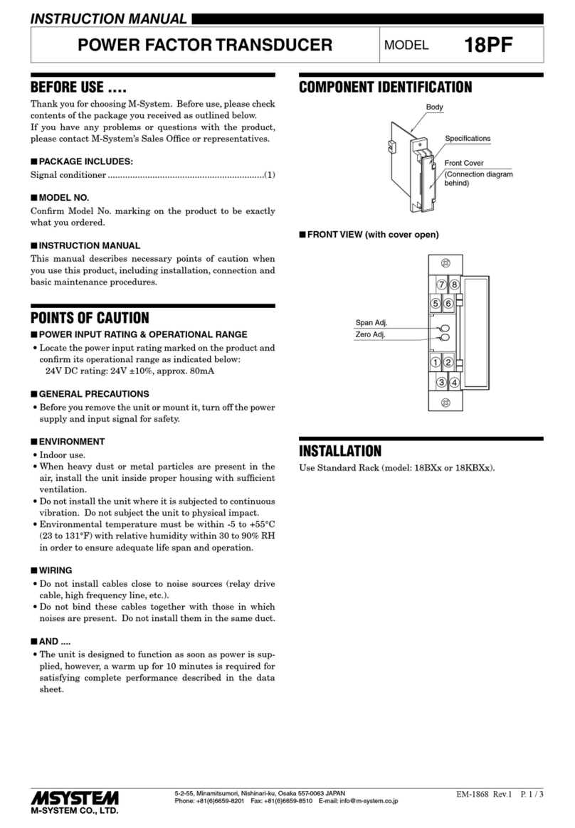
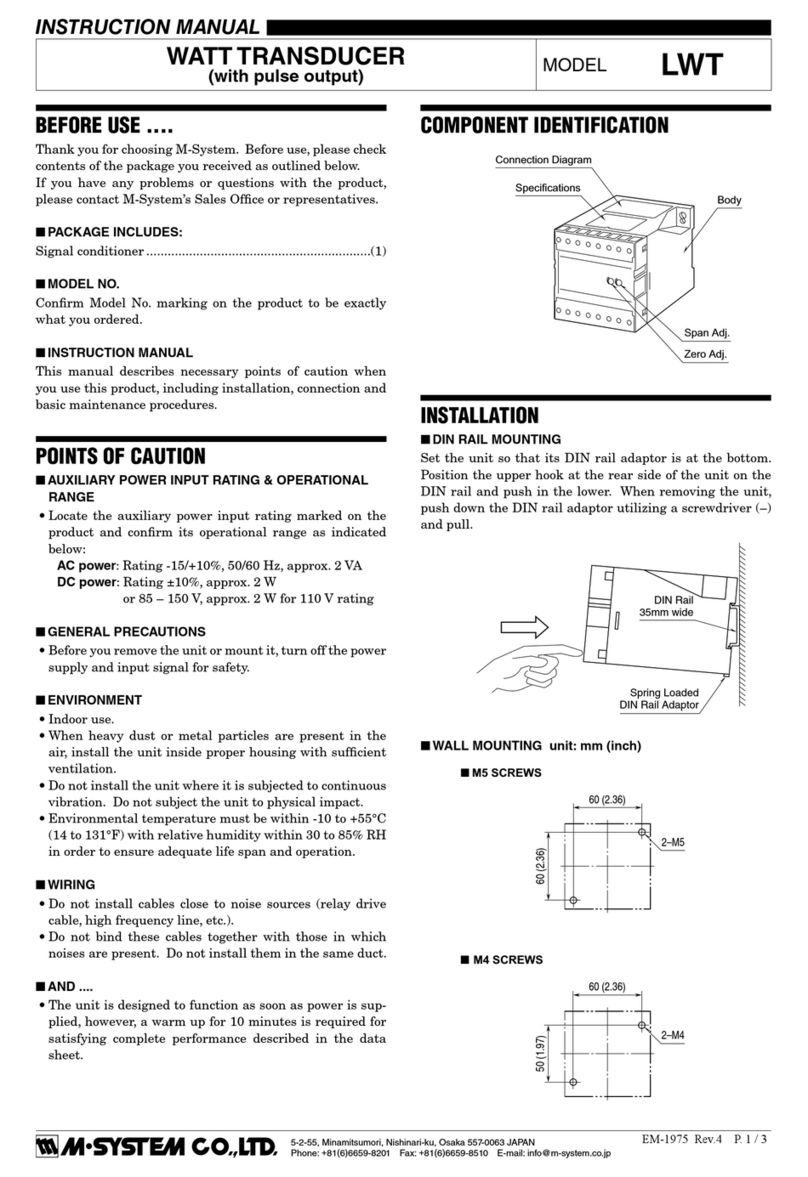
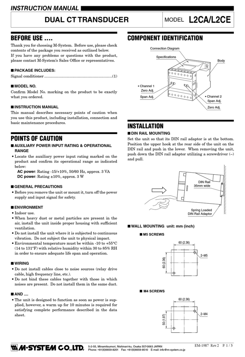
Set the unit so that its DIN rail adapter is at the bottom.
■MOUNTING THE UNIT ON A DIN RAIL
A)Hang the upper hook at the rear side of unit on the DIN
rail.
B)Push in the lower in keeping pressing the unit to the DIN
rail.
A
B
DIN rail
■REMOVING THE UNIT
A)Pull down the DIN rail adaptor using a minus screwdriv-
er.
B)Pull out the lower part of the unit.
C)Remove the upper part from the DIN rail.
A
Slider
C
B
M5XWTU
5-2-55, Minamitsumori, Nishinari-ku, Osaka 557-0063 JAPAN
Phone: +81(6)6659-8201 Fax: +81(6)6659-8510 E-mail: info@m-system.co.jp
EM-2768-A Rev.4 P. 2 / 4
TERMINAL CONNECTIONS
Connect the unit as in the diagram below or refer to the connection diagram on the side of the unit.
■EXTERNAL DIMENSIONS unit: mm [inch]
94 [3.70]3 [.12]
25 [.98] 41 [1.61] (3.3 [.13])
• When mounting, no extra space is needed between units.
DIN RAIL
35mm wide
8–M3.5 SCREW
7.3 [.29]
12
34
56
78
■CONNECTION DIAGRAM
1
8
2
4
7
1K
Current sensor
Voltage input
COM
P2
P1
P3
3K
3
5
6
JACK
CONFIGURATOR
+
–
Analog output
DOa
DOb
Pulse / alarm output
DA
DB
Modbus
■TERMINAL CONNECTIONS
P1 P2 P3 1K 3K
source load
uv vu
UV VU
kl
KL
kl
KL
P1 P2 P3 1K 3K
R
source load
N
T
R
S
T
R
N
T
R
S
T
kl
KL
kl
KL
P1 P2 1K
R
source load
N
kl
KL
uv
UV
P1 P2 1K COM COM
COM
COM
R
source load
N
kl
KL
System/
Application
Single-phase/
2-wire
Note: Use CLSE for CT.
Grounding is unnecessary for low-voltage circuit.
  Apply voltage to P1 - P2 to generate internal power when using simplified measuring mode (fixed voltage value and power factor).
Single-phase/
3-wire
3-phase/
3-wire
Terminal System/
Application Terminal
M5XWTU
5-2-55, Minamitsumori, Nishinari-ku, Osaka 557-0063 JAPAN
Phone: +81(6)6659-8201 Fax: +81(6)6659-8510 E-mail: info@m-system.co.jp
EM-2768-A Rev.4 P. 3 / 4
MODBUS WIRING CONNECTION
HOST PC
DA
DB
DG
SLD
FG
DA
DB
M5XWTU
Terminator*1
Terminator*1
*1. Turn the terminator DIP SW ON to use internal terminator.
■HOST PC WIRING
WIRING INSTRUCTIONS
■SCREW TERMINAL
Torque: 0.8 N·m
EXTERNAL VIEWS
Modbus
■FRONT VIEW
Terminator DIP SW
for Modbus
Te rm On
Power Indicator LED
Configurator Jack
■LEFT VIEW
Analog output
Analog Output Setting
DIP SW
1
2
3
4
5
6
SW1
On
PC CONFIGURATOR
Configuration by the PC is required for each setting. In addition, setting DIP SW is also required for analog output.
Refer to the users manual for the PMCFG for detailed operation of the software program.
Table 1. DIP switch setting: Output type
Output Type SW1
1 2 3 4 5 6
0 – 20 mA ON OFF OFF OFF ON OFF
-5 – +5 V OFF ON ON OFF OFF ON
-10 – +10 V OFF ON OFF ON OFF ON
M5XWTU
5-2-55, Minamitsumori, Nishinari-ku, Osaka 557-0063 JAPAN
Phone: +81(6)6659-8201 Fax: +81(6)6659-8510 E-mail: info@m-system.co.jp
EM-2768-A Rev.4 P. 4 / 4
CHECKING
1) Terminal wiring: Check that all cables are correctly con-
nected according to the connection diagram.
2) Check DIP switch setting.
3) Power input voltage: Check voltage across the terminal
7 – 8 – 4 with a multimeter.
POWER INDICATOR LED
The transmitter is provided with a power indicator LED
which blinks in different patterns indicating various oper-
ating status.
The following figure indicates typical patterns.
LEDONOFFPATTERNSTRANSMITTERSTATUS
Downloadingthesetting
Looptest
Normal
AbnormalOperation
(corruptionofconfigurationdata)
80ms
LIGHTNING SURGE PROTECTION
M-System offers a series of lightning surge protector for
protection against induced lightning surges. Please contact
M-System to choose appropriate models.

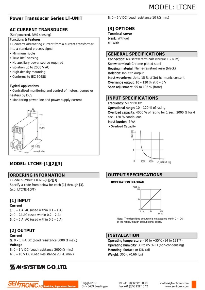
Other M-system Transducer manuals

M-system L3PK User manual

M-system

M-system L3PK User manual

M-system W2PV User manual

M-system

M-system W2PV User manual

M-system Mini-M M2PV User manual

M-system

M-system Mini-M M2PV User manual

M-system LT-UNIT Series User manual

M-system

M-system LT-UNIT Series User manual

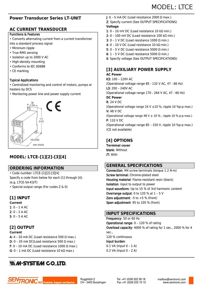
M-system LTCE User manual

M-system

M-system LTCE User manual

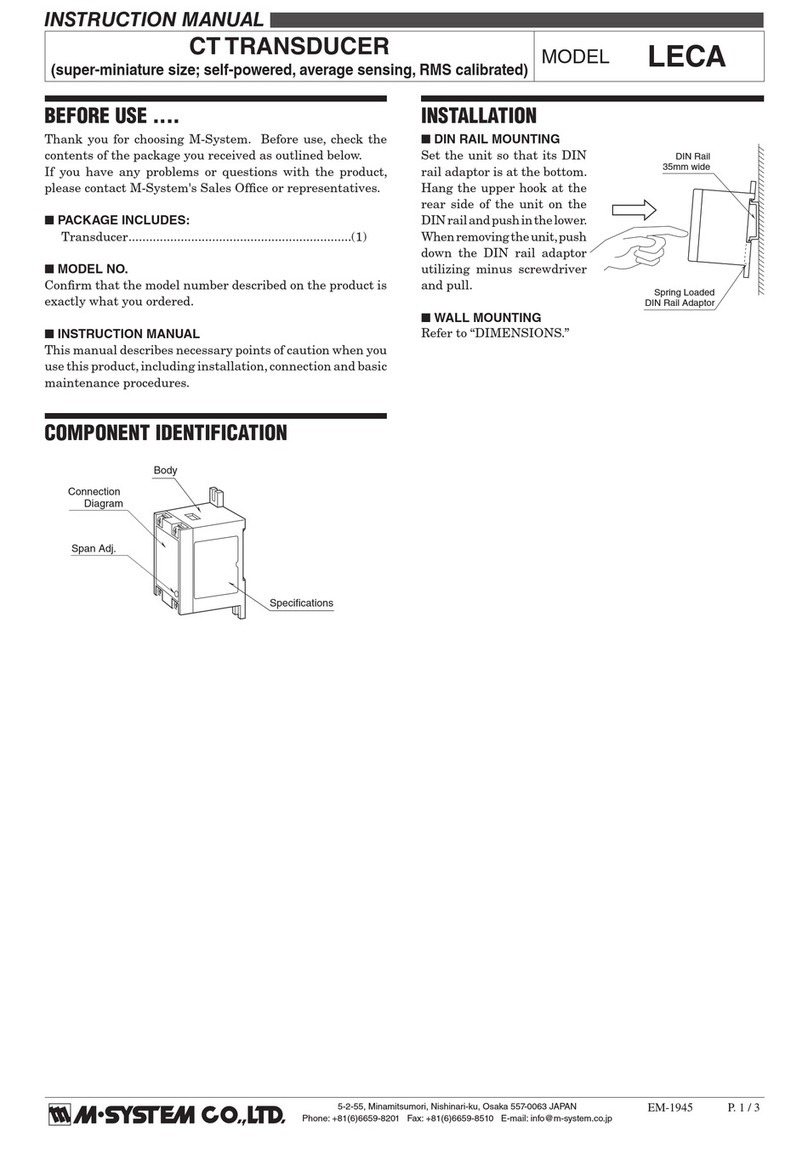
M-system LECA User manual

M-system

M-system LECA User manual

M-system BPV User manual

M-system

M-system BPV User manual

M-system LT-UNIT Series User manual

M-system

M-system LT-UNIT Series User manual

M-system HVPN User manual

M-system

M-system HVPN User manual

M-system LWT User manual

M-system

M-system LWT User manual

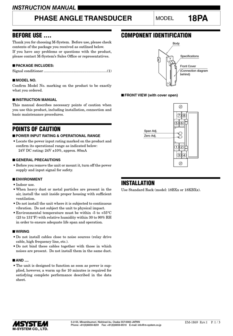
M-system 18PF User manual

M-system

M-system 18PF User manual

M-system 18RP User manual

M-system

M-system 18RP User manual

M-system L2CA User manual

M-system

M-system L2CA User manual

M-system 18PV User manual

M-system

M-system 18PV User manual

M-system KUWEN User manual

M-system

M-system KUWEN User manual

M-system LTCNE User manual

M-system

M-system LTCNE User manual

M-system 18HZ User manual

M-system

M-system 18HZ User manual

M-system LTCE User manual

M-system

M-system LTCE User manual

M-system LTWTN User manual

M-system

M-system LTWTN User manual

M-system L3CK User manual

M-system

M-system L3CK User manual

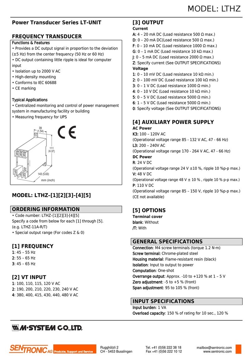
M-system LTHZ User manual

M-system

M-system LTHZ User manual

M-system TPV User manual

M-system

M-system TPV User manual

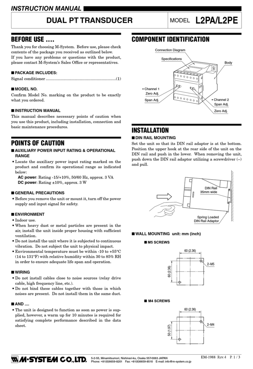
M-system L2PA User manual

M-system

M-system L2PA User manual

M-system PV User manual

M-system

M-system PV User manual

Popular Transducer manuals by other brands

American Printing House for the Blind Braille Plus 18 user guide

American Printing House for the Blind

American Printing House for the Blind Braille Plus 18 user guide

Shinkawa CV-86 Series instruction manual

Shinkawa

Shinkawa CV-86 Series instruction manual

Aposun SRTM instruction manual

Aposun

Aposun SRTM instruction manual

novotechnik RSM-2800 user manual

novotechnik

novotechnik RSM-2800 user manual

Ashcroft KM15 instruction sheet

Ashcroft

Ashcroft KM15 instruction sheet

SIAP+MICROS t055 TPIR User manual and maintenance

SIAP+MICROS

SIAP+MICROS t055 TPIR User manual and maintenance

KEPO DAP9050-F3 specification

KEPO

KEPO DAP9050-F3 specification

S+S Regeltechnik PREMASGARD 111 Series Operating Instructions, Mounting & Installation

S+S Regeltechnik

S+S Regeltechnik PREMASGARD 111 Series Operating Instructions, Mounting & Installation

Clark Synthesis TST429 installation guide

Clark Synthesis

Clark Synthesis TST429 installation guide

HBM U3 Mounting instructions

HBM

HBM U3 Mounting instructions

Multitek PowerSig M560-AT operating manual

Multitek

Multitek PowerSig M560-AT operating manual

Siemens EchoMax ST-H Quick start manual

Siemens

Siemens EchoMax ST-H Quick start manual

controlair 550 Series Installation, operation and maintenance instructions

controlair

controlair 550 Series Installation, operation and maintenance instructions

Endress+Hauser Cerabar T PMC131 technical information

Endress+Hauser

Endress+Hauser Cerabar T PMC131 technical information

Airmar Ultrasonic TRIDUCER UDST800 Owner's guide and installation instructions

Airmar

Airmar Ultrasonic TRIDUCER UDST800 Owner's guide and installation instructions

HBM PW15iA Mounting instructions

HBM

HBM PW15iA Mounting instructions

Mianyang Weibo Electronic WBV411S07 user manual

Mianyang Weibo Electronic

Mianyang Weibo Electronic WBV411S07 user manual

Hydac HLT 1100 Series user manual

Hydac

Hydac HLT 1100 Series user manual

manuals.online logo
manuals.online logoBrands
  • About & Mission
  • Contact us
  • Privacy Policy
  • Terms and Conditions

Copyright 2025 Manuals.Online. All Rights Reserved.