manuals.online logo
Brands
  1. Home
  2. •
  3. Brands
  4. •
  5. Honeywell
  6. •
  7. Control Unit
  8. •
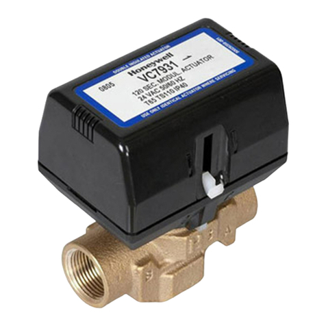
  9. Honeywell VSxF-2 User manual

Honeywell VSxF-2 User manual

® U.S. Registered Trademark MU1B-0404GE51 R0209
Copyright © 2009 Honeywell Inc. • All Rights Reserved EB-VSM-VSO
FI Asennusohje
S Installation instruktioner
N Installationsinstruktioner
DK Installasjonsinstruktus
NL Installatievoorschrift
D Montageanweisung
F Instructions d'installation
ES Instrucciones de montaje
I Istruzioni di montaggio
VSxC / VSxF
2-WAY / 3-WAY / 3-WAY VALVES WITH BYPASS
INSTALLATION INSTRUCTIONS
PN 16
ϑmax. 120 °C
A
BA
M MM
Ventil im Rücklauf.
Valve in the return.
Vanne sur le retour.
Ventil i returledning.
Afsluiter in de retour.
Valvola sul ritorno.
Venttiili asennettuna paluujohtoon.
Válvula sobre retorno.
Ventil i returløb.
Ventil im Vorlauf.
Valve in the flow.
Vanne sur le .
Ventil i framledning.
Afsluiter in de aanvoer.
Valvola sul mandata.
Venttiili asennettuna menojohtoon.
Válvula sobre .
Ventil i fremløb.
départ
impulsión
PN 16
ϑmax. 120 °C
A
BA
B
PN 16 + BYPASS
ϑmax. 120 °C
A
BA
B
AB
B
A
M
Beimischschaltung: Ventil als Mischer
im Vorlauf.
Mixing system: Valve as a mixer in the flow.
Couplage en mélange: Vanne sur le départ
montée en mélange.
Blandningsventil i framledning.
Mengschakeling: Afsluiter als mengorgaan
in de aanvoer.
Sistema a miscelazione: Valvola montata
come miscelatrice sulla mandata.
Sekoituskytkentä: Sekoitusventtiili
menovedessä.
Montaje como mezcladora: Válvula
montada como mezcladora en la impulsión.
Blandeventil i fremløb.
AB
B
A
M
Umlenkschaltung: Ventil als Mischer
im Rücklauf.
Diverting system: Valve as a mixer in return.
Couplage en répartition: Vanne sur le retour
montée en mélange.
Blandningsventil i returledning.
: Afsluiter als mengorgaan
in de retour.
Sistema a deviazione: Valvola montata
come miscelatrice sul ritorno.
Ohituskytkentä: Sekoitusventtiili
paluuvedess .
Montaje como diversora: Válvula
montada como mezcladora en el retorno.
Blandeventil i returløb.
Mengschakeling
ä
AB
B
A
M
Einspritzschaltung: Ventil als Mischer
im Rücklauf.
Injection system: Valve as a mixer in return.
Couplage en injection: Vanne sur le retour
montée en mélange.
Blandningsventil i returledning.
Injectie-mengschakeling: Afsluiter als
mengorgaan in de retour.
Sistema ad iniezione: Valvola montata
come miscelatrice sul ritorno.
Vakiokierto: Sekoitusventtiili paluuvedessä.
Montaje inyección: Válvula montada
como mezcladora en el retorno.
Blandeventil i returløb med doobeltshunt.
VSxC / VSxF – MOUNTING INSTRUCTIONS
MU1B-0404GE51 R0209 2
VSxC-2 / VSxF-2
D EINBAU
1. Im Vorlauf oder im Rücklauf möglich.
2. Im Rücklauf vorziehen, da dort niedrigere Temperaturen herrschen.
3. Wenn vorhanden, nach Rohrleitungsplan einbauen und Durchflusszeichen
auf dem Ventilgehäuse beachten: →
ES MONTAJE
1. En impulsión o en retorno
2. Preferentemente, en el retorno, porque es menor la temperatura.
3. Móntese según los esquemas Hidráulicos del proyecto; no obstante hay que
respetar el sentido de flujo marcado sobre el cuerpo de la válvula: →
E INSTALLATION
1. Either in the flow or the return pipework.
2. Preferably in the return due to the lower temperature conditions there.
3. If an installation plan is available, valve should be mounted at the location
indicated. Note direction of flow indicated on the valve body: →
S MONTERING
1. Ventilen är lämplig för montering i fram-och returledning.
2. Montering i returledning är att föredra pä grund av där förekommande lägre
temperatur.
3. Montera ventilen i enlighet med rörschemat om sådant finns tillgängligt men
alltid under beaktande av flödessybolen på ventilhuset: →
F MONTAGE
1. Possible sur le départ ou sur le retour.
2. De préférence sur le retour car les températures y sont plus basses.
3. Monter selon le plan de raccordement hydraulique s'il existe; observer
toutefois le sens d'écoulement marqué sur le corps de la vanne: →
SF ASENNUS
1. Mahdollinen meno- tai paluujohtoon.
2. Suositellaan paluujohtoa, koska siellä alhaisempi lämpötila.
3. Asennus suoritetaan putkistokaavion mukaan. Aina on kuitenkin
noudatettava venttiilin runkoon nuelella merkittyä läpivirtaussuuntaa: →
I MONTAGGIO
1. Sulla mandata o sul ritorno.
2. E`preferibile il montaggio sul ritorno per la minore temperatura del fluido.
3. Effettuare il montaggio secondo lo schema impiantistico, rispettando le
indicazioni esistenti sul corpo valvola: →
DK MONTERING
1. Montering mulig i fremløb eller returløb.
2. Montering sker bedst i returløb, da temperaturene er lavere der.
3. Hvis der findes en rørplan, foretages montering i henhold til denne. Bemærk
dog gennemstrømningspilen pa ventilhuset: →
NL MONTAGE
1. In annvoer of retour mogelijk.
2. Bij voorkeur in de retour omdat daar lagere temperaturen heersen.
3. Indien aanwezig, volgens leiding ontwerp, met inachtname van het op de
afsluiter aanwezig zijnde stromingsteken: →
VSxC-3 / VSxF-3, VSxC-4 / VSxF-4
D EINBAU
Wenn vorhanden, nach Rohrleitungsplan einbauen und Durchflußzeichen auf
dem Ventilgehäuse beachten:
A =Geregelter Teilstrom; AB = Gesamtstrom; B = Beipaß-Teilstrom
ES MONTAJE
Móntese según los esquemas hidráulicos del proyecto; no obstante hay que
respectar los sentidos de flujo marcados sobre el cuerpo de la válvula:
A = Caudal variable regulado; AB = Caudal total; B = Caudal variable de by-pass
E INSTALLATION
If an installation plan is available, valve should be mounted at the location
indicated. The flow direction must always correspond with the symbol on the
valve body:
A = controlled port (variable); AB = total flow; B = bypass port (variable)
S MONTERING
Montera ventilen i enlighet med rörschemat, om sadant finns tillgängligt men alltid
under beaktande av flödessymbolen på ventilhuset:
A = reglerat delflöte; AB = totalflöde; B = förbigangsflöde
F MONTAGE
La vanne doit être montée à l’endroit indiquée dans le plan de raccordement
hydraulique. Il faut respecter le sens de la flèche qui figure sur le corps de la
vanne:
A = débit variable réglé; AB = débit total du fluide; B = débit variable by-pass
SF ASENNUS
Venttiili tulisi asentaa putkistokaavion mukaan. Noudata venttiilin runkoon nuolella
merkittyä läpivirtaussuuntaa:
A = säädetty virtaus; AB = kokonaisvirtaus; B = ohitusvirtaus
I MONTAGGIO
Effettuare il montaggio secondo lo schema impiantistico, rispettando le indicazioni
esistenti sul corpo valvola:
A = via diritta; AB = portata totale (via sempre aperta); B = via di by-pass
DK MONTERING
Hvis der findes en rørplan, foretages montering i henhold til denne. Bemærk dog
gennemstrømningspilen på ventilhuset:
A = Tilgang; AB = Femløb; B = Shunttilslutning
NL MONTAGE
Installeren volgens leidingsschema (indien voorhanden) en rekening houden met
de doorstroompijl op het kleppenhuis:
A = Geregeld gedeelte; AB = Gezamelijke stroom; B = Bypass gedeelte
VSxC / VSxF – MOUNTING INSTRUCTIONS
MU1B-0404GE51 R0209
3
DIMENSIONS
*NOTE: In the case of modulating valves, the stroke amounts to
6.5 mm, and the closure distance to 18 mm. In the case
of ON/OFF valves, the stroke amounts to 2.5 mm, and the
closure distance to 14 mm.
bb
c
18
6.5 mm STROKE*
a
M30x1.5
ALLOW 130 mm (DN15/20)
OR 150 mm (DN25)
FOR ACTUATOR AND
CLEARANCE FOR
REMOVAL.
Fig. 1. VSxC-2 / VSxF-2 (2-way), dimensions
Table 1. VSxC-2 (2-way), dimensions (in mm)
a b c
DN15 56 G ½ A†32
DN20 66 1-1/8 BS84 34
DN25 76 G 1 ¼ A†48
† ISO 228/1
Table 2. VSxF-2 (2-way), dimensions (in mm)
a b c
DN15 56 G ½ A†32
DN20 66 G ¾ A†34
DN25 76 G 1 ¼ A†48
† ISO 228/1
b
c
b
d
18
a
M30x1.5
6.5 mm STROKE*
ALLOW 130 mm (DN15/20)
OR 150 mm (DN25)
FOR ACTUATOR AND
CLEARANCE FOR
REMOVAL.
Fig. 2. VSxC-3 / VSxF-3 (3-way), dimensions
Table 3. VSxC-3 (3-way), dimensions (in mm)
a b c d
DN15 56 G ½ A†24.5 32
DN20 66 1-1/8 BS84 33 34
DN25 76 G 1 ¼ A†38 48
† ISO 228/1
Table 4. VSxF-3 (3-way), dimensions (in mm)
a b c d
DN15 56 G ½ A†25.5 32
DN20 66 G ¾ A†33 34
DN25 76 G 1 ¼ A†38 48
† ISO 228/1
b
b
b
b
d
c
18
a
M30x1.5
6.5 mm STROKE*
ALLOW 130 mm (DN15/20)
OR 150 mm (DN25)
FOR ACTUATOR AND
CLEARANCE FOR
REMOVAL.
Fig. 3. VSxC-4 / VSxF-4 (3-way with bypass), dimensions
Table 5. VSxC-4 (3-way with bypass), dimensions (in mm)
a b c d
DN15 56 G ½ A†40 32
DN20 66 1-1/8 BS84 40 34
DN25 76 G 1 ¼ A†62.5 48
† ISO 228/1
Table 6. VSxF-4 (3-way with bypass), dimensions (in mm)
a b c d
DN15 56 G ½ A†40 32
DN20 66 G ¾ A†40 34
DN25 76 G 1 ¼ A†62.5 48
† ISO 228/1
DIMENSIONS WITH SNAP-ON
In the case of models featuring a snap-on ring, the actuator can be directly attached
to the valve without having to first mount a ring.
bb
c
2.5 mm STROKE
a
A
LLOW 130 mm
FOR ACTUATOR AND
CLEARANCE FOR
REMOVAL.
Fig. 4. VSxC-2 / VSxF-2 (2-way with snap-on), dimensions
Table 7. VSxC-2 / VSxF-2 (2-way with snap-on), dimensions (mm)
a b c
DN15 56 G ½ A†34.5
DN20 (VSxC-2) 66 1-1/8 BS84 36.6
DN20 (VSxF-2) 66 G ¾ A†36.6
† ISO 228/1
b
c
b
d
a
2.5 mm STROKE
ALLOW 130 mm
FOR ACTUATOR AND
CLEARANCE FOR
REMOVAL.
Fig. 5. VSxC-3 / VSxF-3 (3-way with snap-on), dimensions
VSxC / VSxF – MOUNTING INSTRUCTIONS
Manufactured for and on behalf of the Environmental and Combustion Controls Division of Honeywell Technologies Sàrl, Rolle, Z.A. La Pièce 16, Switzerland by its Authorized Representative:
Automation and Control Solutions
Honeywell GmbH
Böblinger Strasse 17
71101 Schönaich
Germany
Phone: (49) 7031 63701
Fax: (49) 7031 637493
http://ecc.emea.honeywell.com
Subject to change without notice. Printed in Germany
MU1B-0404GE51 R0209 / EB-VSM-VSO Rev. B
Table 8. VSxC-3 / VSxF-3 (3-way with snap-on), dimensions (mm)
a b c d
DN15 56 G ½ A†24.5 34.5
DN20 (VSxC-3) 66 1-1/8 BS84 33 36.6
DN20 (VSxF-3) 66 G ¾ A†33 36.6
† ISO 228/1
b
b
b
b
d
c
a
2.5 mm STROKE
ALLOW 130 mm
FOR ACTUATOR AND
CLEARANCE FOR
REMOVAL.
Fig. 6. VSxC-4 / VSxF-4 (3-way with bypass + snap-on), dimensions
Table 9. VSxC-4 / VSxF-4 (3-way with bypass + snap-on), dimensions (in mm)
a b c d
DN15 56 G ½ A†40 34.5
DN20 (VSxC-3) 66 1-1/8 BS84 40 36.6
DN20 (VSxC-3) 66 G ¾ A†40 36.6
† ISO 228/1
ACCESSORIES
VSxF Valves
DN type
be
15
20
AC-15 FS
AC-20 FS
bg
15
20
25
AC-15 FT
AC-20 FT
ACS-25 T
type b e g
AC-15 FS G ½ 12 -
AC-15 FT G ½ - R 3/8”
AC-20 FS G ¾ 15 -
AC-20 FT G ¾ - R ½”
ACS-25 T G 1 ¼ -- R 1”
VSxC Valves
ISO 7/1 DN type
e
b
15
20
ACN-15 C
ACN-20 C
f
b
15
20
ACN-15 S
ACN-20 S
g
b
15
20
25
ACN-15 T
ACN-20 T
ACN-25 T
Conex fitting
(not available from
Honeywell)
15
20
63 (15 mm)
65 (15 mm)
63 (22 mm)
65 (22 mm)
type b e f g
ACN-15 C G ½ 15 mm - -
ACN-15 S G ½ - 12 mm -
ACN-15 T G ½ - - R 3/8”
ACN-20 C 1-1/8 x 14 BS 84 22 mm - -
ACN-20 S 1-1/8 x 14 BS 84 - 15 mm -
ACN-20 T 1-1/8 x 14 BS 84 -- - R ½”
ACN-25 T G 1 ¼ -- -- R 1”

This manual suits for next models

5

Other Honeywell Control Unit manuals

Honeywell 7800 SERIES Operation manual

Honeywell

Honeywell 7800 SERIES Operation manual

Honeywell D06F User manual

Honeywell

Honeywell D06F User manual

Honeywell Hometronic HB 05 User manual

Honeywell

Honeywell Hometronic HB 05 User manual

Honeywell VR4300 User manual

Honeywell

Honeywell VR4300 User manual

Honeywell RF CM61NG User manual

Honeywell

Honeywell RF CM61NG User manual

Honeywell VP513A User manual

Honeywell

Honeywell VP513A User manual

Honeywell V1810 Alwa-Kombi-4 User manual

Honeywell

Honeywell V1810 Alwa-Kombi-4 User manual

Honeywell MV300 User manual

Honeywell

Honeywell MV300 User manual

Honeywell PRO4200 User manual

Honeywell

Honeywell PRO4200 User manual

Honeywell TM3400 User manual

Honeywell

Honeywell TM3400 User manual

Honeywell SmartPAC 2 User manual

Honeywell

Honeywell SmartPAC 2 User manual

Honeywell JADE W7220 User manual

Honeywell

Honeywell JADE W7220 User manual

Honeywell V5055A-E User manual

Honeywell

Honeywell V5055A-E User manual

Honeywell 7800 SERIES User manual

Honeywell

Honeywell 7800 SERIES User manual

Honeywell THP9045 User manual

Honeywell

Honeywell THP9045 User manual

Honeywell NOTIFIER M701E User manual

Honeywell

Honeywell NOTIFIER M701E User manual

Honeywell 2MLL-PSRA User manual

Honeywell

Honeywell 2MLL-PSRA User manual

Honeywell LC13-510 User manual

Honeywell

Honeywell LC13-510 User manual

Honeywell ADEMCO 4204 User manual

Honeywell

Honeywell ADEMCO 4204 User manual

Honeywell PS300 User manual

Honeywell

Honeywell PS300 User manual

Honeywell RA116A User manual

Honeywell

Honeywell RA116A User manual

Honeywell D22 User manual

Honeywell

Honeywell D22 User manual

Honeywell Prestige THX9421R02 User manual

Honeywell

Honeywell Prestige THX9421R02 User manual

Honeywell Temaline TK-S014 User manual

Honeywell

Honeywell Temaline TK-S014 User manual

Popular Control Unit manuals by other brands

Burkert 3320 quick start guide

Burkert

Burkert 3320 quick start guide

Feig Electronic OBID i-scan ID ISC.LRM2500-B installation manual

Feig Electronic

Feig Electronic OBID i-scan ID ISC.LRM2500-B installation manual

NXP Semiconductors TWR-KL43Z user guide

NXP Semiconductors

NXP Semiconductors TWR-KL43Z user guide

Electroline Control Unit IV Reference manual

Electroline

Electroline Control Unit IV Reference manual

BROWER TIMING SYSTEM MC Series instructions

BROWER TIMING SYSTEM

BROWER TIMING SYSTEM MC Series instructions

ABB Ability 800xA Series user manual

ABB

ABB Ability 800xA Series user manual

REMKO Smart Com Instructions for use

REMKO

REMKO Smart Com Instructions for use

System Sensor M500M Installation and maintenance instructions

System Sensor

System Sensor M500M Installation and maintenance instructions

Hitachi S10Mini SV.Link Hardware manual

Hitachi

Hitachi S10Mini SV.Link Hardware manual

MTF KD59E instructions

MTF

MTF KD59E instructions

Eaton XNE-1SWIRE user manual

Eaton

Eaton XNE-1SWIRE user manual

A.R.I. Eliptix R-30 R 2W Installation, Operating, Maintenance

A.R.I.

A.R.I. Eliptix R-30 R 2W Installation, Operating, Maintenance

Metal Work HDM series user manual

Metal Work

Metal Work HDM series user manual

SMC Networks VZ400 Series quick start guide

SMC Networks

SMC Networks VZ400 Series quick start guide

Kohler K-10673 Maintenance Guide

Kohler

Kohler K-10673 Maintenance Guide

Xtreme Power Systems XtremeLink Installation and usage manual

Xtreme Power Systems

Xtreme Power Systems XtremeLink Installation and usage manual

Siensor UNIC user guide

Siensor

Siensor UNIC user guide

PVA SB300 owner's manual

PVA

PVA SB300 owner's manual

manuals.online logo
manuals.online logoBrands
  • About & Mission
  • Contact us
  • Privacy Policy
  • Terms and Conditions

Copyright 2025 Manuals.Online. All Rights Reserved.