Gemotech RemoDAQ-8017SV User manual

V1.1 2009.02.11
RemoDAQ-8017SV/SC
User’s Manual
Beijing Gemotech Intelligent Technology Co.,Ltd

RemoDAQ-8017S User’s Manual
Copyright Notice
This document is copyrighted, 2005, by Beijing Gemotech
Intelligent Technology Co.,Ltd.
All rights are reserved. Beijing Gemotech Intelligent
Technology Co.,Ltd reserves the right to make
improvements to the products described in this manual at any
time without notice.
No part of this manual may be reproduced, copied,
translated or transmitted in any form or by any means without
the prior written permission of Beijing Gemotech Intelligent
Technology Co.,Ltd. Information provided in this manual is
intended to be accurate and reliable. However, Beijing
Gemotech Intelligent Technology Co.,Ltd assumes no
responsibility for its use, or for any infringements upon the
rights of third parties, which may result from its use.
Acknowledgments
RemoDAQ is a trademark of Beijing Gemotech Intelligent
Technology Co.,Ltd.
Edition 1.1
Feb. 2009
1

RemoDAQ-8017S User’s Manual
Additional Information and Assistance
1. Visit the Gemotech websites at www. gemotech.cn
where you can find the latest information about the product.
2. Contact your distributor, sales representative, or
Gemotech 's customer service center for technical support if
you need additional assistance. Please have the following
information ready before you call:
zProduct name and serial number
zDescription of your peripheral attachments
zDescription of your software (operating system,
version,application software, etc.)
zA complete description of the problem
zThe exact wording of any error messages
2

RemoDAQ-8017S User’s Manual
Table of Contents
1 Introduction ..............................................................................................4
1.1 PinAssignment & Specifications ..............................................5
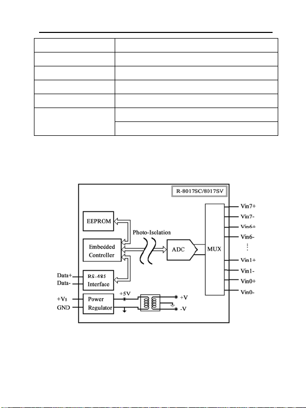
1.2 Block Diagram...........................................................................6
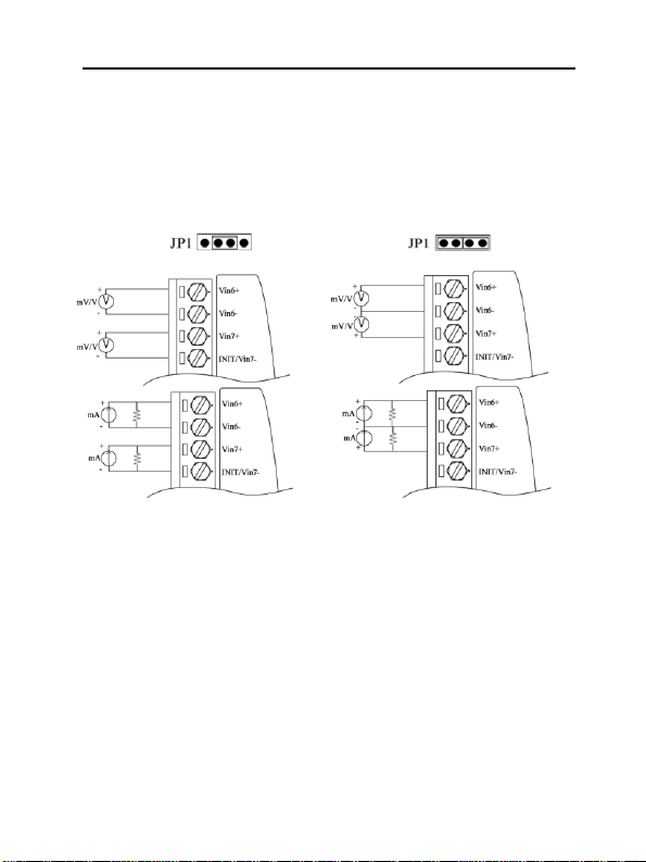
1.3 Application Wiring ....................................................................7
1.4 Default Setting ...........................................................................8
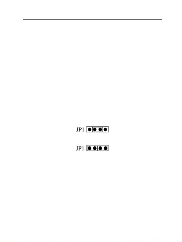
1.5 Jumper Setting............................................................................8
1.6 Calibration..................................................................................8
1.7 Install List ................................................................................10
2 Initialization & Installation....................................................................12
2.1 Installation Guideline...............................................................12
2.2 Software Installation................................................................12
2.3 Basic configuration and hook-up.............................................13
2.4 Baudrate and Checksum ..........................................................15
3 Command Set .........................................................................................17
3.1 %AANNTTCCFF....................................................................20
3.2 #AA..........................................................................................22
3.3 #AAN.......................................................................................23
3.4 $AA0........................................................................................24
3.5 $AA1........................................................................................25
3.6 $AA2........................................................................................26
3.7 $AA5VV..................................................................................27
3.8 $AA6........................................................................................28
3.9 $AA3V.VVVV ........................................................................29
3.10 $AA4±VV..............................................................................30
3.11 $AAA.....................................................................................31
3.12 $AAF......................................................................................32
3.13 $AAM ....................................................................................33
3.14 ~AAO(Data)...........................................................................34
3.15 ~AAEV ..................................................................................35
3

RemoDAQ-8017S User’s Manual
1 Introduction
The RemoDAQ-8000 Series is a set of intelligent sensor to
computer interface modules containing built in microproces-
sor. They are remotely controlled through a simple set of
commands issued in ASCII format and transmitted in RS-485
protocol. They provide signal conditioning, isolation, ranging,
A/D and D/A conversion, data comparison, digital commun-
ication, timer/counter, wireless communication, collection
AC and other functions.
RemoDAQ-8017SV is an 8-channel voltage input module.
RemoDAQ-8017SC is an 8-channel current input module.
The common features of AI modules are given as following:
z3000VDC Isolated analog input
z24-bits sigma-delta ADC to provide excellent accuracy.
zSoftware calibration
zTVS / PTC preponderate over Voltage protect
4

RemoDAQ-8017S User’s Manual
1.1 Pin Assignment & Specifications
R
emoDAQ-8017SC/SV Specifications:
Channel 8 differential or 6 differential and 2 single-ended.
Input type mA(8017SC);V(8017SV)
Input range -20mA~ 20mA(8017SC);-5V~+5V(8017SV)
Output
Speed (in bps)
Maximum distance
RS-485 (2-wire)
1200,2400,4800,9600,19.2K,38.4K,57.6K,115.2K
4000ft. (1200m.)
Accuracy ±0.5% or better
Zero drift 20µV/°C
Span drift 25ppm/°C
Isolation voltage 3000VDC
CMR@50/60Hz 86dB
Bandwidth 15.7Hz
5

RemoDAQ-8017S User’s Manual
Conversion rate 6.8 samples/sec
Input impedance 10MΩ
Overvoltage Protection 20VP-P
Power supply 10~30VDC
Power consumption 1.3W
Operating Temperature:-20 ~ 70° C
Environment Humidity:5 ~ 95%, non-condensing
1.2 Block Diagram
6

RemoDAQ-8017S User’s Manual
1.3 Application Wiring
RemoDAQ-8017SC/SV
AI Channel 6 and 7 AI Channel 6 and 7 Wire
Wire Connection,while the jumper Connection,while the jumper JP1
JP1 setting is 8 differential mode setting is INIT* mode
Notice:
1. RemoDAQ-8017SC measure current wire connection,
please refer RemoDAQ-8017,But no external 125Ωresistor.
2. Because modular is internal to set signal protective
circuit,under the condition that does not supply power can
affect as normal signal produces,so must install and gather
signal under ensuring the condition of normal power supply,
and cut off or stop gathering signal before modular broken
electricity.
7

RemoDAQ-8017S User’s Manual
1.4 Default Setting
zAddress:01
zBaudrate:9600 bps
zAnalog output type:
RemoDAQ-8017SC:-20mA~+20mA
RemoDAQ-8017SV:-10V~+10V
z60Hz filter rejection, Checksum disable, engineering unit
format
zSet as 6 differential and 2 single-ended mode
1.5 Jumper Setting
Jumper JP1 for select the pin INIT*/Vin 7-
Select 8-diff mode,the pin INIT*/Vin7- is set to Vin7-
Select INIT* mode,the pin INIT*/Vin7- is set to INIT*
1.6 Calibration
What do you need to do calibration?
1. One 5 1/2 digital multimeter.
2. A voltage calibrator or very stable and noise free DC
voltage generator.
3. A precision resistance decade box or discrete resistors.
4. RemoDAQ-8000 Utility
8

RemoDAQ-8017S User’s Manual
RemoDAQ-8017SV:
Type code:09
Zero input:0V
Span input:5V
RemoDAQ-8017SC:
Type code:0D
Zero input:0mA
Span input:20mA
Notice:
1. Apply power to the module and let it warm up for about 30 minutes
2. Connect calibration voltage(or current) signal to module’s input.
For RemoDAQ-8017SC/SV connect to channel 0.
Calibrate for RemoDAQ-8017SC
1. Setting type to 0D
2. Enable calibration
3. Apply zero calibration voltage
4. Perform $AA4+VV command,until 0
5. Perform zero calibration command
6. Apply span calibration voltage
7. Perform $AA3V.VVVV command,until 20mA
8. Perform span calibration command
9. Repeat step 2 to step 8 three times.
Calibrate for RemoDAQ-8017SV
1. Setting type to 09
2. Enable calibration
9

RemoDAQ-8017S User’s Manual
3. Apply zero calibration voltage
4. Perform $AA4+VV command,until 0
5. Perform zero calibration command
6. Apply span calibration voltage
7. Perform $AA3V.VVVV command,until 5V
8. Perform span calibration command
9. Repeat step 2 to step 8 three times.
1.7 Install List
Baudrate Setting (CC)
Code 03 04 05 06 07 08 09 0A
Baudrate 1200 2400 4800 9600 19200 38400 57600 115200
A
nalog Input Type Setting (TT)
RemoDAQ-8017SC:Code 09
Min -5V
Max +5V
RemoDAQ-8017SV:Code 0D
Min -20mA
Max +20mA
Data format setting(FF)
7 6 5 4 3 2 1 0
*1 *2 0 *3
*1:0=60Hz Restrain 1=50Hz Restrain
10

RemoDAQ-8017S User’s Manual
*2:Checksum:0=Disabled 1=Enable
*3:00 = Engineering unit Format
01 = Percent Format
10 = 2’s Complement HEX Format
Analog Input Type And Data Format Table
Code Input span Data format +F.S. Zero -F.S
Project Unit +5.000 +00.000 -5.000
%(FSR)+100.000 +000.00 -100.00
09 +5V~+5V
2’s Complement HEX
7FFF 0000 8000
Project Unit +20.000 +0.0000 -20.000
%(FSR)+100.000 +000.00 -100.00
0D -20mA~+20mA
2’s Complement HEX
7FFF 0000 8000
11

RemoDAQ-8017S User’s Manual
2 Initialization & Installation
2.1 Installation Guideline
Figure 2-1 Power Supply Connections
We advise that the following standard colors (as indicated
on the modules) be used for power lines:
+Vs (R) Red
GND (B) Black
We advice that the following standard colors (as indicated
on the modules) be used for the communication lines:
DATA+ (Y) Yellow
DATA- (G) Green
2.2 Software Installation
1. If you have already installed “RemoDAQ-8000 Utility”
then skip other steps.
2. Backup your software diskette.
3. Insert “RemoDAQ-8000 Utility” disc into CD-ROM:
4. Change drive to the path of CD-ROM. For example,
12

RemoDAQ-8017S User’s Manual
your drive of CD-ROM is F:then change the drive to F:
5. Find the setup of “RemoDAQ-8000 Utility” and run it.
6. Please follow the steps of setup program then you can
successfully install the RemoDAQ-8000 Utility.
2.3 Basic configuration and hook-up
Before placing a module in an existing network, the
module should be configured.Though all modules are initially
configured at the factory, it is recommended to check that the
baud rate is set correctly.
Default Factory Settings
Baud rate:9600 Bit/sec.
Address:01 (hexadecimal)
Checksum:disable
The basic hook-up for module configuration is shown below.
Figure 2-2 Layout for Initialization the RemoDAQ module
13

RemoDAQ-8017S User’s Manual
The following items are required to configure a module:a
RemoDAQ
converter module, a personal computer with
RS-
232 port (baudrate set to 9600) and theRemoDAQ utility software.
Configuration with the RemoDAQ Utility Software
The easiest way to configure the RemoDAQ module is by
using the RemoDAQ utility software:an easy-to-use menu-
structured program will guide you through every step of the
configuration.
Configuration with the RemoDAQ command set
RemoDAQ modules can also be configured by issuing
direct commands from a terminal emulation program within
what is part of the RemoDAQ utility software.
The following example guides you through the setup of an
analog input module. Assume that RemoDAQ-8017SV still
has its default settings (baud rate 9600 and address 01h).
Before the module is reconfigured, it is first requested to send
its default settings.
To change the configuration setting of the analog input
module, the following command is issued:
%01070D0600(cr)
% = change configuration
01 = target module at address 00 to:
07 = change address to 07 hexadecimal
0D = set input range to Type 0D
06 = set baud rate to 9600
00 = set integration time to 50 ms (60 Hz)
disable checksum
14

RemoDAQ-8017S User’s Manual
set data format to engineering units
(See Chapter 3, Command Set for a full description of the
syntax of the configuration command for module)
When the module received the configuration command it will
respond with its new address:!07(cr)
NOTICE:All reconfiguration except changing of baud rate
and checksum values can be done dynamically, i.e. the
modules need not to be reset. When changing the baud rate or
checksum, these changes should be made for all connected
devices. After reconfiguration, all modules should be
powered down and powered up to force a reboot and let the
changes take effect.
2.4 Baudrate and Checksum
RemoDAQ modules contain EEPROMs to store
configuration information and calibration constants. The
EEPROM replaces the usual array of switches and ports
required to specify baudrate, input/output range etc.
All of the RemoDAQ modules can be configured remotely
through their communication ports, without having to
physically alter port or switch settings.
Forcing the module in the INIT* state does not change any
parameters in the module’s EEPROM. When the module is in
the INIT* state with its INIT* and GND terminals shorted, all
configuration settings can be changed and the module will
respond to all other commands normally.
15

RemoDAQ-8017S User’s Manual
Changing Baud rate and Checksum
Baud rate and checksum settings have several things in common
:
¾
They should be the same for all modules and host computer.
¾
Their setting can only be changed by putting a module in the
INIT* state.
¾Changed settings can only take effect after a module is rebooted
To alter baudrate or checksum settings you must perform the
following steps:
¾Power on all components except the RemoDAQ Module.
¾Power the RemoDAQ module on while shorting the
INIT* and GND terminals
¾Wait at least 7 seconds to let self calibration and ranging
take effect.
¾Configure the checksum status and/or the baud rate.
¾Switch the power to the RemoDAQ Module OFF.
¾Remove the grounding of the INIT* terminal and power
the module on.
¾Wait at least 7 seconds to let self calibration and ranging
take effect.
¾Check the settings (If the baud rate has changed, the
settings on the host computer should be changed
accordingly.)
16

RemoDAQ-8017S User’s Manual
3 Command Set
Introduction
To avoid communication conflicts when several devices try
to send data at the same time, all actions are instigated by the
host computer. The basic form is a command/response
protocol with the host initiating the sequence.
When modules are not transmitting they are in listen mode.
The host issues a command to a module with a specified
address and waits a certain amount of time for the module to
respond. If no response arrives, a timeout aborts the sequence
and returns control to the host.
Changing RemoDAQ’s configuration might require the
module to perform auto calibration before changes can take
effect. Especially when changing the range, the module has to
perform all stages of auto calibration that it also performs
when booted. When this process is under way, the module
does not respond to any other commands.
The command set includes the exact delays that might
occur when modules are reconfigured.
Syntax
[delimiter character][address][command][data][checksum]
[carriage return]
Every command begins with a delimiter character. There
are four valid characters:a dollar sign $, a pound sign #, a
percentage sign % and an at sign @.
17

RemoDAQ-8017S User’s Manual
The delimiter character is followed by a two-character
address (hexadecimal) that specifies the target module. The
actual two-character command follows the address.
Depending on the command, an optional data segment
follows the command string. An optional two character
checksum may be appended to the total string. Every
command is terminated by a carriage return (cr).
Calculate Checksum:
1. Calculate ASCII sum of all characters of command(or
response) string except the character return(cr).
2. Mask the sum of string with 0ffh.
Example:
Command string:$012(cr)
Sum of string=‘$’+‘0’+‘1’+‘2’=24h+30h+31h+32h=B7h
The checksum is B7h,and [CHK] = “B7”
Command string with checksum:$012B7(cr)
Response string:!01200600(cr)
Sum of string:‘!’+‘0’+‘1’+‘2’+‘0’+‘0’+‘6’+‘0’+‘0’
=1h+30h+31h+32h+30h+30h+36h+30h+30h=1AAh
The checksum is AAh,and [CHK] = “AA”
Response string with checksum:!01200600AA(cr)
18

RemoDAQ-8017S User’s Manual
General Command Sets
Command Syntax Command Name Command Description Notes
%AANNTTCCFF Configuration
Sets the address,input range,
baudrate,dataformat,checksum status 3.1
#AA Analog data in Return the input value from the
module in the currently configured
data format 3.2
#AAN Analog data in Return the input value from the
module channels N in the currently
configured data format 3.3
$AA0 Span calibration
Calibrates an AI module to correct
for gain errors 3.4
$AA1 Zero Calibration Calibrates an AI module to correct
for gain errors 3.5
$AA2 Configuration status
Return the configuration parameters fo
r
the module
3.6
$AA5VV Enable/Disable channels
for multiplexing
Enable or disable the individual channels 3.7
$AA6 Read channel status Get the enable/disable status of all
channels 3.8
$AA3V.VVVV Set span coefficient Return correct or error 3.9
$AA4±VV Set zero excursion Return correct or error 3.10
$AAA Read 8 channels
input value
Return the input value from the
module 8 channels in the currently
configured data format 3.11
$AAF Read firmware version Return the firmware version code 3.12
$AAM Read module name Return the module name 3.13
~AAO(data) Set module name Return correct or error 3.14
~AAEV Enable/Disable
calibration Return correct or error 3.15
19
This manual suits for next models
1
Table of contents
Popular Control Unit manuals by other brands

Xtralis
Xtralis ADPRO HeiTel IFM-485-ST Quick installation guide

Honeywell
Honeywell TR120 installation instructions

Envirofan
Envirofan 105FR Installation and operating instructions

Motion Control Engineering
Motion Control Engineering Nidec iControl user guide

Belimo
Belimo B2100VB-024 Technical documentation

ETC
ETC SmartModule 2 installation guide