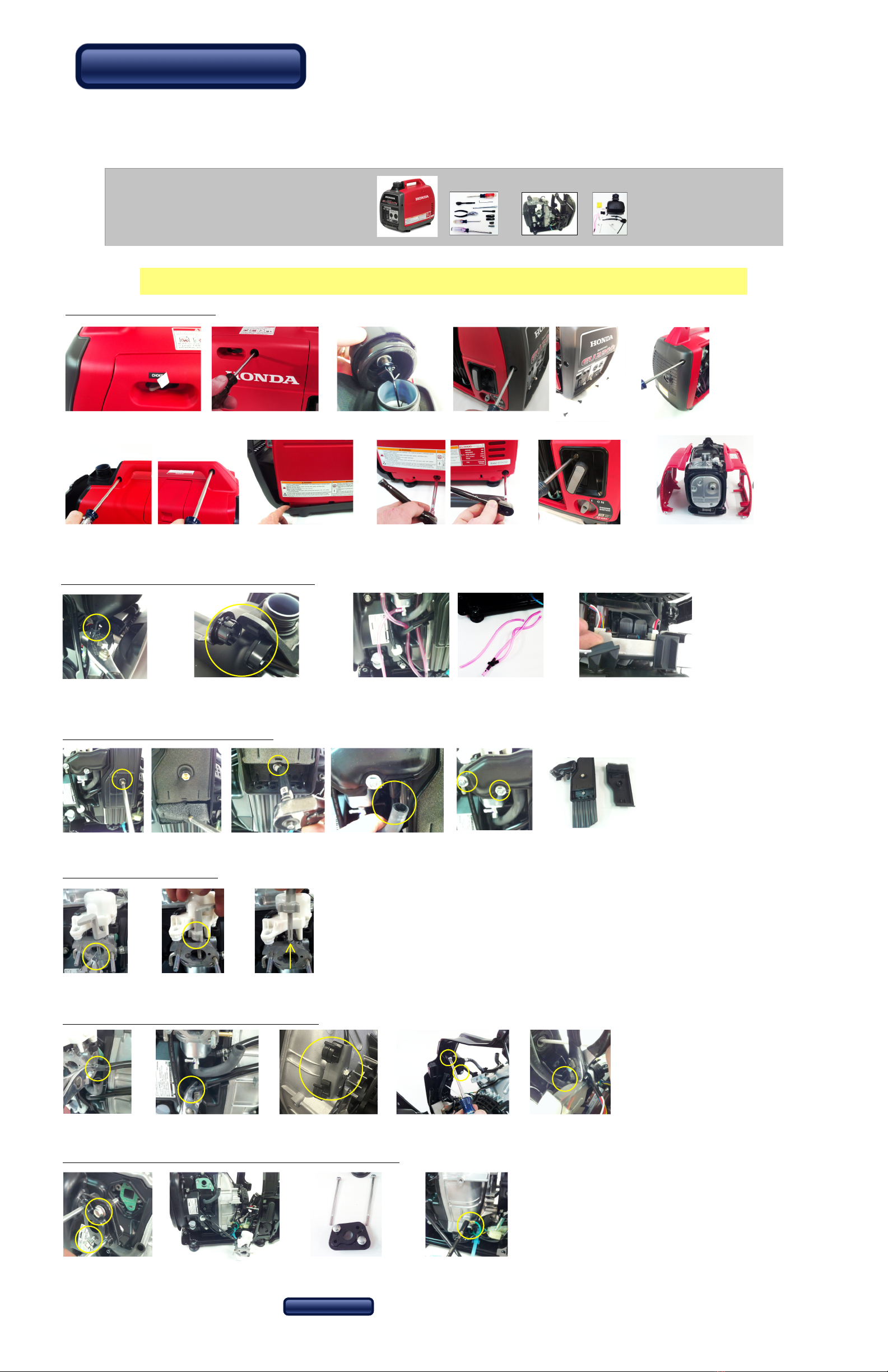
Step 2A - nstall gas module nto frame
+=
2a-1 Install module
from top seating it in both
gas tank side holders
2a-2 Install ground strap
using previously removed
ground screw.
2a-3 Test air purge knob
to make sure lever
engages spring button
and returns into seated
position without binding.
Step 2B - Re- nstall carburetor
2b-1/2 Insert new long screws then re-attach block to engine.2b-3/4 Re-install gasket then slide carburetor back on
Make sure servo wire is not tight on left side.
2b-5/6/7 Install red caps on carburetor inlets, small black cap
inside choke lever hole, and large black cap over crankcase port.
Step 2E - Re- nstall skins
2e-1/2/3/4-install side skins by first installing ‘wood’ screw above pull starter then install top two
screws starting with back end screw. 2e-7 Re-install trim (snap in place),
then install back plastic cover.
Step 2F - Add labels
2e-5/6 install bottom two 10mm long
hex bolts starting with back bolt.
Engineered to the next level.
Genconnex®
Step 2
Re-assembly
WARN NG:
Propane is a combustible fuel. t should be kept outdoors at all times, f you suspect a leak in you generator or
any hoses / connections, you should immediately turn off the fuel at the tank then test connections with soapy
water. Do not attempt to use any components including hoses that have leaks. Replace them immediately.
Copyright 2020 New England Gen-Connect LLC. All rights reserved.
90-2004
Replace oil with fully
synthetic 5W-30 for cold climates
or 10W-30 for warmer climates
Read supplied
“Owner’s Manual Supplement”
Step 2H - Additional steps
Step 2D - Attach fuel hose and close up air box
2c-1/2 Slide on the new gasket then slide on the fuel
nozzle assembly then slide on the old gasket.
2d-1/2/3 Push fuel line all the way onto brass injector, then install
air filter element, air filter cover then crankcase install vent tube.
2c-3/4/5/6 Push the fuel line into the upper or lower clamp in bracket and route under bottom tab. Do not attach fuel hose to
nozzle assembly yet. Place air cleaner 8mm bolt through air cleaner body and add three supplied washers on backside. Hold
onto washer and slide air cleaner onto upper two carburetor studs. Tighten 8mm bolt then install and tighten two supplied 3/8”
locking nuts to hold carburetor and injector assembly (you may need to hold 4” bolt from turning by gently pressing on side of
exposed threads with finger while tightening nut).
2f-1/2/3 Attach “Genconnex start” label on door next to pull start and the small “Propane” label
below it, the LARGE “Propane” Label on opposite side and a small “Propane” label on the back.
For all states except California place Emissions label over existing EPA/CARB label on engine
frame near oil dip stick. For California place Emissions label next to existing EPA label on
engine frame near oil dip stick.
2e-8 Gently tighten two nozzle clamp screws from
inside but do not deform front edge of red skins or
front cover won’t fit properly. Install front & rear
cover. Also pull up and down primmer ball on top
to make sure it moves freely. Back off slightly if it
starts to bind. Then fasten front cover in place.
http://www.genconnexdirect.net/techcenter/index.htm
On-Line PDF
2g-4 If a high-altitude kit is needed,
change the fuel jet in the end of the
fuel tube with the supplied allen head
wrench.
Step 2G - High Altitude Orifice
Step 2C - nstall fuel injection module & air cleaner housing