manuals.online logo
Brands
  1. Home
  2. •
  3. Brands
  4. •
  5. General Filters
  6. •
  7. Humidistat
  8. •
  9. General Filters MHX3C User manual

General Filters MHX3C User manual

Please Read And Save These Instructions
• Installationbyanyoneotherthanaqualiedcontractorvoidsthewarranty.
• Productdesignedforresidentialinstallationonly.Commercialinstallationvoidswarranty.
• Modicationoralterationofproduct,parts,installationinstructionsorlocalsafetycodesvoidswarranty.
• Readourfullwarrantypolicyattheendofthisdocument.
Breathe Healthier
About the MHX3C Digital Humidistat
The MHX3C control provides low voltage control of most humidiers. The humidistat uses a SPDT switch and is designed
for wall mounting in the living area or mounting on the return air duct.
WARNING! Always TURN OFF POWER TO THE HVAC SYSTEM prior to installing or servicing the humidier or
humidistat. Improper operation can result in over or under humidication. Improper voltage can cause malfunction or
damage to the control. All local building and electrical codes must be followed. The technical specications for this
product and the contents of the user manual are subject to change without notice.
WARNING! Do not set relative humidity too high during cold weather. Over humidication can result in condensation,
structural damage and mold.

!

!
Canadian General Filters, Ltd.
400 Midwest Rd.
Toronto, ON M1P3A9 Canada
Toll Free: (888) 216-9184
www.cgfproducts.com
General Filters, Inc.
43800 Grand River Avenue
Novi, Michigan 48375
Toll Free: (866) 476-5101
www.generalaire.com
MHX3C Humidistat
(GFI #7038)
Installation Manual
GENERAL FILTERS
INCORPORATED
2
Model MHX3C Humidistat Installation Manual
MHX3C Locations
Specifications
RANGE: 10% to 75% RH ELECTRICAL RATING: 30 VAC, 60 VA
The MHX3C can be congured for operation as a standard humidistat, high limit humidistat, or dehumidistat. When
using this product as a standard humidistat terminals "NO" and "C" must be used. When using this product as a high
limit humidistat terminals "NO" and "C" and must be used. When using this product as a dehumidistat terminals "NC"
and "C" must be used. Use DHD3 Dial (GFI #7061) for the dehumidistat version.
WALL MOUNTING INSTRUCTIONS - Humidistat/Dehumidistat Versions
1. Chose a location for the MHX3C about ve feet above the oor on an inside wall with average room
temperature and relative humidity conditions. Drill a small hole in the wall and run low voltage wiring to the
location chosen. Pull about 6” of wire through the hole.
2. Gaskets: Use the entire thin mounting gasket (both inside and outside portions) to seal the wall opening or
use foam tape to prevent drafts from affecting the humidistat operation. Do NOT install the thick gasket.
(see FIG. 1)
3. Squeeze the top and bottom of the base to release the face of the humidistat.
4. Mount the base horizontally over the wires. Attach directly to the wall, using the two screws provided in the
slotted holes.
5. Connect wires to screw terminals on the control assembly as shown in DIAGRAMS 1-5. Replace the face.
DUCT MOUNTING ON THE RETURN AIR - WALL BASE
Humidistat/Dehumidistat versions (optional)
Do not install the humidistat on the warm air duct or within 48” of UV light.
1. Locate the humidistat at least 24" upstream of the humidier or bypass on the return air duct. Avoid areas of
direct radiation like secondary heat exchangers in the fan compartment. Cut a square hole in the duct 2-1/4”
wide and 1-3/4” tall.
2. Gaskets: Remove the inner portion of the mounting gasket and discard. Use the outer portion to seal between
the plastic base and the duct. Place the thick gasket inside the wall mount base to seal off air entering through
the vents. Line up the base with the cut out and accurately mark the holes thru the plastic duct mount plate.
(see FIG. 1)
3. Remove the humidistat and drill four 3/32” mounting holes.
4. Place the outer portion of the mounting gasket on the plastic base and mount the base with four screws. Low
voltage wire may enter the humidistat under the gasket.
5. Connect wires to screw terminals on the control assembly as shown in DIAGRAMS 1-5. Replace the face.
Wall or Duct Mount
Thin Gasket
Face FIG. 1
WALL MOUNT: Use
Outer & Inner Portions
DUCT MOUNT: Use
ONLY Outer Portion
Mounting
Base
Thick Gasket
DUCT MOUNT ONLY
3
www.generallters.com
Model MHX3C Humidistat Installation Manual
Wiring Diagrams
DIAGRAM 2: Wiring High Limit Humidistat With
Elite Steam Humidifiers
DIAGRAM 3: Wiring 120V 1137/1000 Power Humidifiers
With Furnace Supplied 120V
DIAGRAM 4: Dehumidifier
DIAGRAM 1: Wiring 24V Bypass Humidifier
(Models 570, 900, 1042LH, 1099LHS, SL16)
N2
GND
N1
AB
AB
GND
IN
NO
C
NC
C
NO
GND
24V
MHX3
Humidistat
High Limit
Humidistat
Use Terminals 2 and 3 On Humidistat
Steam Humidier Control Module
MHX3C
Humidistat
727-58
24V Transformer
(Omit if Power Supply is
20-30 VAC) Humidier 24V
Solenoid Valve
Or 24V Drum Motor
(Model 81)
120V Power Supply
Switched With Furnace Operation
Use Terminals 2 and 3 On
Humidistat
L1 N
G
Humidier Control Leads
(Yellow Wires)
Humidier
Power Cord
Humidier 24V Aux Power
(Red Wires)
120V Switched With Furnace Heating Cycle
DIAGRAM 5: Wiring 120V 1137/1000 Power Humidifiers
With Constant 120V Supply
Humidier Control Leads
(Yellow Wires) Humidier
Power Cord
Humidier 24V Aux Power
(Red Wires)
L1 N
G
727-58
24V Transformer
(Omit if Power Supply
is 20-30 VAC)
120V Switched With
Furnace Heating Cycle
120V Constant Voltage
(Not Used, Attach Wire
Nuts to Each Lead) Do
Not Touch Together!
DHD3 Dehumidistat Dial
GFI #7061
CRD3 Humidistat Dial
GFI #7058
Optional Accessories
NC C
NO
NC C
NO
NC C
NO
Dehumidier
MHX3C
Humidistat
Use Terminals 2 and 1 For
Dehumidistat
DH
G2
S1
S2
G1
C
W
Y
D
NC C
NO
NC C
NO
G

!WARNING: ALL WIRING SHOULD COMPLY WITH LOCAL ELECTRICAL CODES.
(Not Used, Attach Wire
Nuts to Each Lead) Do
Not Touch Together!
Relay
MHX3C
Humidistat
MHX3C
Humidistat
4
Model MHX3C Humidistat Installation Manual
Limited Warranty
This humidistat is warranted to the consumer against defects in materials and workmanship for a period of one year from the date
of installation. Defective parts will be repaired without charge except for removal, reinstallation and transportation costs. To obtain
repair service under this limited warranty, the consumer must send the defective part to the manufacturer.
There are no express warranties covering this humidistat other than set forth above. The implied warranties of merchantability and
tness for a particular purpose are limited in duration to one year. The manufacturer assumes no liability in connection with the
installation or use of this product, except as stated in this limited warranty. The manufacturer will in no event be liable for incidental
or consequential damages.
Any questions pertaining to this limited warranty should be addressed to the manufacturer. USA: The manufacturer has elected not
to make available the informal dispute settlement mechanism which is specied in the Magnuson-Moss Warranty Act.
Troubleshooting
Humidifier turns on and off repeatedly:
1. If mounted on wall, verify wire clearance hole in wall is sufciently insulated to prevent drafts from affecting the humidistat.
2. If mounted on return air duct, verify humidistat is at least 24” upstream of humidiers air discharge.
Humidifier operates continuously:
1. When the humidity in the home is less than the knob setting on the humidistat the stat will operate the humidier until the
humidity is higher. Reduce knob setting.
2. Verify function of solenoid valve.
No humidifier operation in “ON” mode:
1. Set the thermostat to operate both furnace burner and blower. Operation may be necessary for system power.
2. Verify terminals "NO" and "C" are used on the humidistat. These are the contacts for humidication.
3. Check voltage at terminals "NO" and "C". There should be no voltage for an Elite Steam or 1137/1000 power humidier.
Voltage should be 20-30 VAC from most others.
4. Verify humidier operation by bypassing the humidistat.
Ideal humidity is not achieved:
1. Excess air inltration. Seal sources of air loss.
2. Technical fault with humidier. Check water supply, electrical connections and condition of the evaporator pad. Verify metering
orice at the solenoid valve is not obstructed.
3. Humidier run time is too short. Switch water supply to hot water if appropriate (use copper tubing).
4. Humidier is undersized. Switch water supply to hot water if appropriate (use copper tubing). Add additional unit(s) or replace
existing unit with a larger unit.
Using the MHX3C
USA: www.GeneralFilters.com
USA: Toll Free (866) 476-5101
If you do not have on-line access, please mail a postcard with your name, phone number, email address, product
purchased, model number, date of purchase, serial number, and contractor contact information to:
USA: General Filters, Inc. 43800 Grand River Ave Novi, MI 48375
Canada: 400 Midwest Road Toronto, ON, M1P 3A9 Canada
Canada: www.CGFProducts.com
Canada: Toll Free (888) 216-9184
WARNING: Turn off power before performing maintenance.
CAUTION: Maintenance should be performed only by a qualified contractor.

!

!
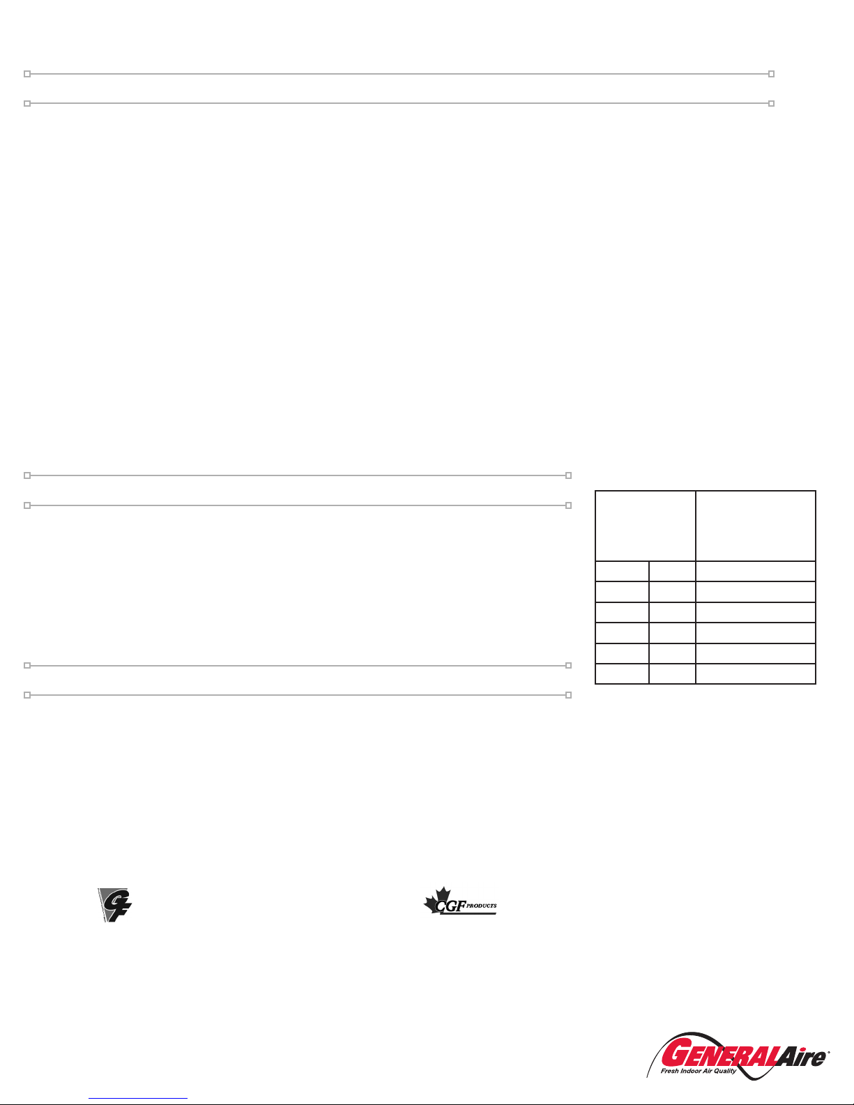
To adjust humidity using your MHX3C, simply turn the dial to the left or right. Turning to the left,
towards the number 75, increases humidity output. Turning the dial to the right, or the number 10,
decreases the humidity output.
After each adjustment, wait 2-3 days before adjusting again. This is how long it can take for new
humidity levels to reach all areas of your home.
Ideal humidity is between 40 and 60%. See additional recommended settings to the right.
At Outside
Temperature
Recommended
Setting
-20°F -29°C 15%
-10°F -23°C 20%
0°F -18°F 25%
+10°F -12°C 30%
+20°F -7°C 35%
+30°F -1°C 40%
FORM NO. MHX3C _REV B
(8-2018; JPF; InDesign)

Popular Humidistat manuals by other brands

Honeywell HP970A Service data

Honeywell

Honeywell HP970A Service data

Boneco A7056 Instructions for use

Boneco

Boneco A7056 Instructions for use

Nordmann HSN installation instructions

Nordmann

Nordmann HSN installation instructions

Braeburn 229150 instruction manual

Braeburn

Braeburn 229150 instruction manual

Condair 1510142 installation instructions

Condair

Condair 1510142 installation instructions

Vector TCY-BH-U manual

Vector

Vector TCY-BH-U manual

manuals.online logo
manuals.online logoBrands
  • About & Mission
  • Contact us
  • Privacy Policy
  • Terms and Conditions

Copyright 2025 Manuals.Online. All Rights Reserved.