Neptronic HRO20 User manual

Room Humidistat
Specification & Installation Instructions
HRO20/100921 1
T
echnical Data HRO20
Outputs
Actual humidity (0-100%RH), 0-10 Vdc / 2-10 Vdc
Humidity set point (0-100%RH), 0-10 Vdc / 2-10 Vdc
Humidification proportional control signal, 0-10 Vdc / 2-10 Vdc
Dehumidification proportional control signal, 0-10 Vdc / 2-10 Vdc
Humidification dry contracts 24 Vac, 1 A max, 3 A in-rush
Dehumidification dry contracts 24 Vac, 1 A max, 3 A in-rush
Inputs
Window temperature sensor or outside temperature sensor (10 K)
External set point from Neptronic humidifier,
external humidity sensor (0-10 Vdc / 2-10 Vdc) or high limit (0-10 Vdc / 2-10 Vdc)
1 alarm status digital input (24 Vac or dry contact)
Power supply 22 to 26 Vac 50/60 Hz or 28 to 32 Vdc
Power consumption 1 VA
Set point range 10 - 90%RH (in 1% increments)
Sensor precision ± 3% or better at 40%RH and 23ºC [73ºF]
Proportional band 2 % - 10 % for control signal
Electrical connection 0.8 mm2 [18 AWG] minimum
Operating condition 0ºC to 40ºC [32ºF to 104ºF], 0-95%RH
Storage condition -10ºC to 50ºC [14ºF to 122ºF], 0-95%RH
temperature compensation
reset feature Automatic readjustment of set point from a window temperature sensor (SHW0-11)
or external temperature sensor (STC8-11)
Housing degree of protection IP 30 (EN 60529)
Weight 130 g. [0.3 lb]
Interface
C
F
%RH
MO TU WE TH FR SA SU
AM PM
.
.
.
.
Symbols on display
Humidification ON
33,66,100% output
C
or
F
ºC: Celsius scale
ºF: Fahrenheit scale Alarm status
Dehumidification ON
33,66,100% output Menu set-up Lock
%RH Percentage of
humidity Programming mode
(Technician setting)
Dimensions
Dimension Imperial (in) Metric (mm)
A 2.85 73
B 4.85 123
C 1.00 24
D 2.36 60
E 3.27 83
Features:
•Attractive modern look with large LCD and backlight
•Icons driven information and 1 line of text
•External humidity sensor input
•Humidification and dehumidification indicator
•Multi level lockable access menu
•Lockable Set point / Control mode
•Window/outside temperature sensor input
•Celsius or Fahrenheit scale selectable
HRO20
A
B
C
D
E

HRO20 Specification & Installation Instructions
2
Mounting Instructions
A
E
D
C
B
CAUTION: Risk of malfunction. Remove power prior to separate humidistat cover from its base.
A. Remove the screw (captive) holding the base and the front cover of the humidistat.
B. Lift the front cover of the humidistat to separate it from the base.
C. Pull wire through the base hole.
D. Secure the base to the wall using wall anchors and screws (supplied). Make the appropriate connections.
E. Mount the control module on the base and secure using the screw.
Terminal Description
TB1
1 Common
2 24 Vac or 30 Vdc
6 Not used
7 Common Relay
8 Humidify contact output (DO1)
9 Dehumidify contact output (DO2)
10 Humidify set point analog output (AO4) Note: If dehumidify only is selected, AO4 = 0 V
11 Alarm status digital input (DI1)
12 External set point from Neptronic humidifier, external humidity sensor (0-10 Vdc / 2-10 Vdc) or high limit
(0-10 Vdc / 2-10 Vdc) (AI1)
13 Window temperature sensor or outside temperature sensor input (AI2)
14 Humidify analog output (AO1)
15 Dehumidify analog output (AO2)
16 Actual humidity output (0-100%RH) (AO3)
Settings on PC Board
Connecting
strip TB1
Temperature
sensor
TB1
1 2 3 7 8 9 10 11 12 13 14 15 16
Mode selector
JP3
PGM RUN
JP2
Digital output
signal selector
Digital Output Signal Selection (JP2)
24VAC
Jumper (JP2) on left: All digital output
signal is linked to internal 24Vac.
(Same 24Vac than humidistat)
Jumper (JP2) on right: All digital output
signal is linked to external 24Vac.
(Different 24Vac than humidistat)
Mode Selection (JP3)
PGM
RUN
JP3
Jumper (JP3) on RUN:
Humidistat is in operation mode.
Humidistat must be set in this mode to
operate properly.
If not locked, set point may be modified by
end user.
PGM
RUN
JP3
Jumper (JP3) on PGM:
Humidistat is set in Programming mode.
Refer to following section about all settings
description
24VAC EXT.

HRO20 Specification & Installation Instructions
3
Programming Mode
When in this mode this symbol is displayed. Please press on button to advance to the next program function, press on button
to return to preceding stage and press on button or to change value. You can leave the programming mode at any time,
changed values will be recorded.
Step Display Description Values
1%RH
Internal humidity sensor offset calibration:
Display shows “inside humidty sensor offset” and the relative humidity
percentage read by internal humidity sensor. Humidify symbol is also
displayed.
You can adjust the calibration of the sensor by comparing with a known
humidistat. For example if humidistat has been installed in an area where
humidity is slightly different than the room typical humidity (humidistat
installed right under the air diffuser).
Range: 10 to 90%RH
(max. offset ± 5%)
Increment: 0.1%RH
0.0%RH no humidity sensor
(factory calibrated)
2 C
Internal temperature sensor calibration:
Display shows “inside temper sensor offset” and the temperature read
by internal temperature sensor.
You can adjust the calibration of the sensor by comparing with a known
thermometer. For example if thermostat has been installed in an area
where temperature is slightly different than the room typical temperature
(humidistat installed right under the air diffuser).
Range : 10 to 40ºC [50 to 104ºF]
(max. offset ± 5ºC)
Increment: 0.1ºC [0.2ºF]
(factory calibrated)
3 %RH
Minimum set point:
Display shows “adjust minimum user setpnt” and the minimum humidity
set point.
Please select the desired minimum humidity set point.
The minimum value is restricted by the maximum value. (step #4)
Minimum range: 10 to 90%RH
Increment: 1%RH
Default value: 15%RH
4 %RH
Maximum set point:
Display shows “adjust maximum user setpnt” and the maximum humidity
set point.
Please select the desired maximum humidity set point.
The maximum value is restricted by the minimum value. (step #3)
Maximum range: 10 to 90%RH
Increment: 1%RH
Default value: 65%RH
5
Locking the set point:
Display shows “user setpnt locked” and the status of the function.
You can lock or unlock the end user set point adjustment. If locked, “yes”
and lock symbol will appear.
Default value:
Unlocked (NO)
6
Adjust the control mode:
Display shows “adjust control mode”.Humidify or dehumidify symbols
are also displayed.
Select which control mode you want to authorize:
Automatic humidify and dehumidify (Auto), humidify only (Hu) or
dehumidify only (dEHu).
If you have selected dehumidify only, go directly to step #8.
Default value: humidify only
7 %RH
Adjust humidi
f
y set point:
Display shows “adjust humidty setpnt” and the humidity set point.
You can change the humidity set point to the desired value; it should be
within the humidity range.
Lock symbol will appear if the set point was locked at step #5.
Set point value is restricted by the minimum and maximum value. (step
#3 & 4)
If you have selected humidify only at step #6, go directly to step #9.
Set point range: 10 to 90%RH
Increment: 1%RH
Default value: 40%RH

HRO20 Specification & Installation Instructions
4
Step Display Description Values
8
Adjust dehumidify set point:
Display shows “adjust dehumi setpnt” and the dehumidify set point.
You can change the dehumidify set point to the desired value; it should
be within the humidity range.
Lock symbol will appear if the set point was locked at step #5.
Set point value is restricted by the minimum and maximum value. (step
#3 & 4)
Set point range: 10 to 90%RH
Increment: 1%RH
Default value: 50%RH
9
Set On/Off function enable or disable:
Display shows “enable on off control mode”.
You can enable or disable the On/Off function in control mode
adjustment by end user.
If you have selected dehumidify only at step #6, go directly to step
#11.
Default value:
Enable (YES)
10 %RH
Humidify proportional band:
Display shows “humidty control ramp” and the value of humidify ramp.
Humidify symbol is also displayed.
Select the desired span for the humidify ramp.
If you have selected humidify only at step #6, go directly to step #12.
Proportional band: 2 to 10%RH
Increment: 0.5%RH
Default value: 5.0%RH
11 %RH
Dehumidify proportional band:
Display shows “dehumi control ramp” and the value of dehumidify ramp.
Dehumidify symbol is also displayed.
Select the desired span for the dehumidify ramp.
Proportional band: 2 to 10%RH
Increment: 0.5%RH
Default value: 5.0%RH
12 %RH
Control dead band:
Display shows “control dead band” and its value.
Humidify/dehumidify symbol are also displayed since this value applies to
both.
Please select the desired dead band value.
If you have selected dehumidify only at step #6, go directly to step
#14.
Dead band range : 0.3 to 5.0%RH
Increment: 0.1%RH
Default value: 0.3%RH
13
Minimum voltage of AO1 output:
Display shows “min vdc analog ao1 output” and the value of the minimum
voltage of the signal “0.0” for 0 to 10 Vdc or “2.0” for 2 to 10 Vdc.
Humidify symbol is also displayed.
Please select the desired value of the minimum voltage of AO1 output.
If you have selected humidify only at step #6, go directly to step #15.
Range: 0.0 or 2.0 Volt
Default value: 0.0 Volt
14
Minimum voltage of AO2 output:
Display shows “min vdc analog ao2 output” and the value of the
minimum voltage of the signal “0.0” for 0 to 10 Vdc or “2.0” for 2 to 10
Vdc. Dehumidify symbol is also displayed.
Please select the desired value of the minimum voltage of AO2 output.
Range: 0.0 or 2.0 Volt
Default value: 0.0 Volt
15
Minimum voltage of AO3 output:
Display shows “min vdc analog ao3 output” and the value of the
minimum voltage of the signal “0.0” for 0 to 10 Vdc or “2.0” for 2 to 10
Vdc. Humidify symbol is also displayed.
Please select the desired value of the minimum voltage of AO3 output.
If you have selected dehumidify only at step #6, go directly to step
#17.
Range: 0.0 or 2.0 Volt
Default value: 0.0 Volt
%RH

HRO20 Specification & Installation Instructions
5
Step Display Description Values
16
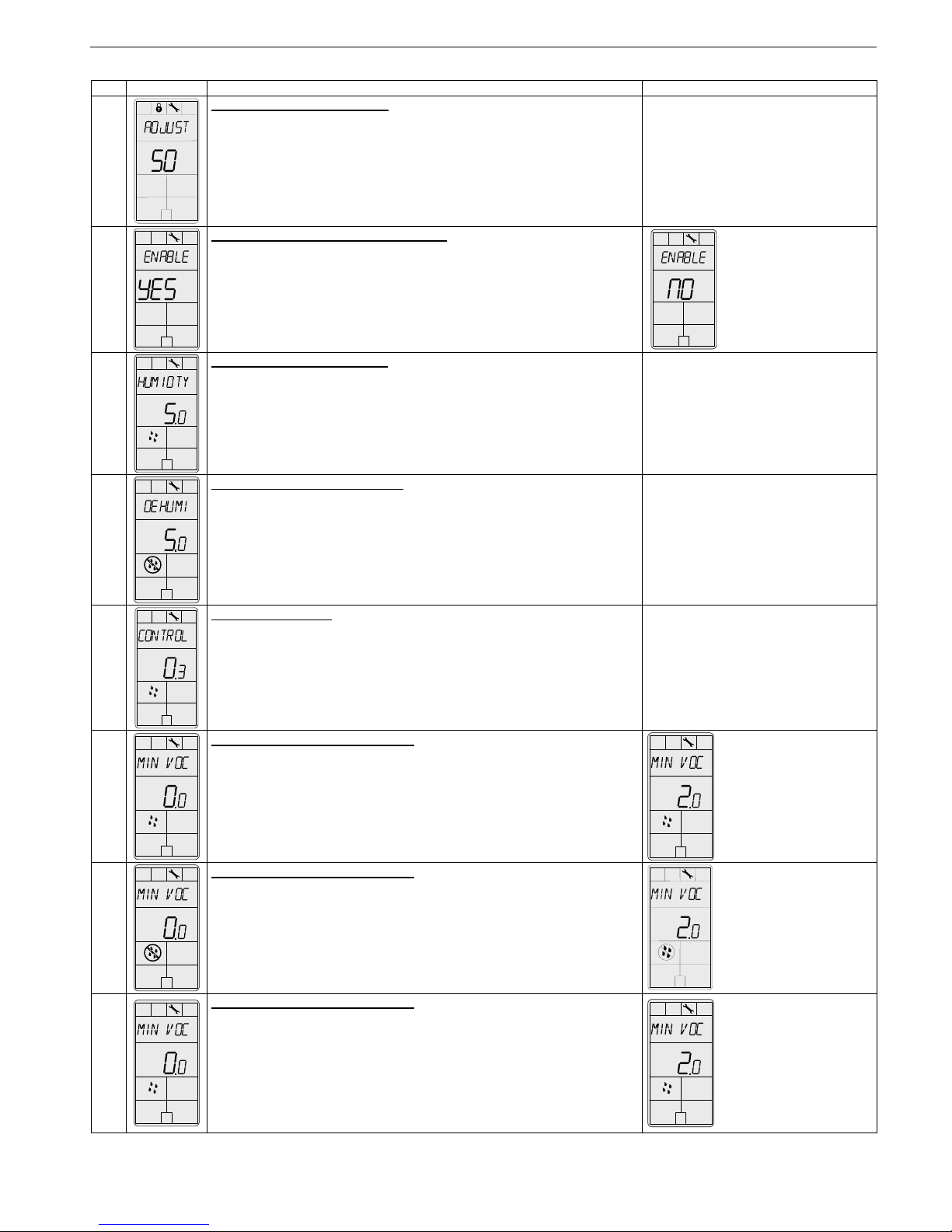
Minimum voltage of AO4 output:
Display shows “min vdc analog ao4 output” and the value of the
minimum voltage of the signal “0.0” for 0 to 10 Vdc or “2.0” for 2 to 10
Vdc. Humidify symbol is also displayed.
Please select the desired value of the minimum voltage of AO4 output.
Range: 0.0 or 2.0 Volt
Default value: 0.0 Volt
17
Set AI1 input signal:
Display shows “select AI1 input signal”.
Select which signal you want for AI1 input.
You can choose:
•OFF (input not used),
•EHS.0 (external humidity sensor 0-10 Vdc),
•EHS.2 (external humidity sensor 2-10 Vdc),
•SPS (external set point from Neptronic humidifier),
•HIL.0 (high limit 0-10 Vdc),
•HIL.2 (high limit 2-10 Vdc).
If you have selected OFF or SPS, go directly to step #20.
Note: If SPS is selected, the dehumidify set point will be disabled.
Default value: OFF
18 %RH
External humidity sensor offset calibration:
(If ‘’EHS.0’’, ‘’ EHS.2’’, ‘’HIL.0’’ or ‘’HIL.2’’ has been selected at step #17)
Display shows “extern humidty sensor offset” and relative humidity
percentage read by external humidity sensor. Humidify symbol is also
displayed.
If the sensor is not connected or short circuited, the display shows “Eror”.
You can adjust the calibration of the sensor by comparison with a known
humidistat. For example if humidistat has been installed in an area where
humidity is slightly different than the room typical humidity.
Range: 10 to 90%RH
(max. offset ± 5%)
Increment: 0.1%RH
0.0%RH = no humidity sensor
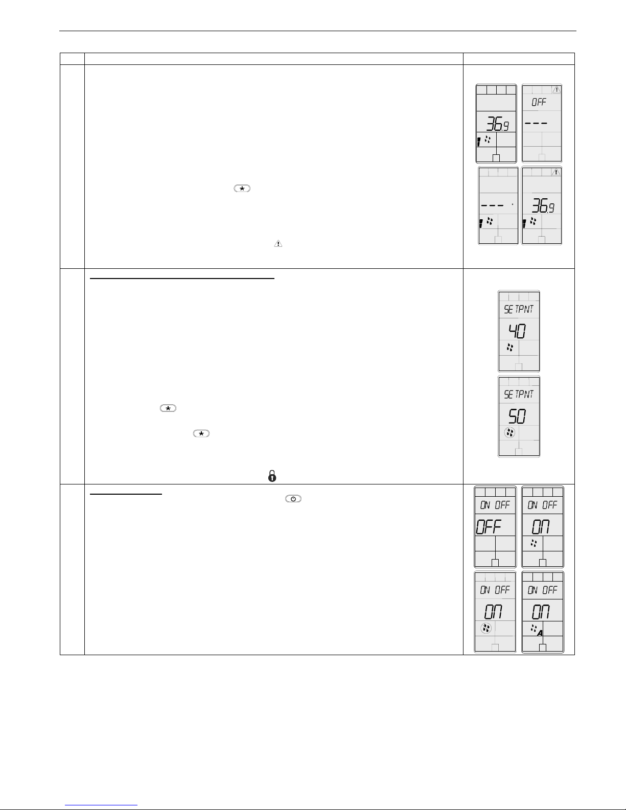
19 %RH
Adjust high limit set point:
(If ‘’HIL.0’’ or ‘’HIL.2’’ has been selected at step #17)
Display shows “adjust setpnt high limit” and the high limit set point.
Select the desired high limit humidity set point; this one should be within
the high limit range.
Set point range: 10 to 90%RH
Increment: 1%RH
Default value: 80%RH
20
Set AI2 input signal:
Display shows “select AI2 input signal”.
Select which signal you want for AI2 input.
You can choose:
•OFF (input not used),
•Wts (Window Temperature Sensor 10K),
•OtS (Outside Temperature Sensor 10K).
If you have selected OFF, go directly to step #1.
Default value: OFF
21 C
External temperature sensor calibration:
(If ‘’WtS’’ or ‘’EtS’’ has been selected at step #20)
Display shows “extern temper sensor offset” and the temperature read
by the external temperature sensor (if connected on the selected input).
If the sensor is not connected or short circuited, the display shows “Eror”.
You can adjust the calibration of the external sensor by comparison with a
known thermometer.
Range: -30 to 90ºC [-22 to 194ºF]
(max. offset ± 5ºC)
Increment: 0.1ºC [0.2ºF]
22
Window temperature sensor compensation factor:
(If ‘’WtS’’ has been selected at step #20)
Display shows “window temper sensor compens” and the value of the
compensation factor.
You can adjust the compensation factor to avoid condensation on the
window.
The lower the compensation factor, the lower the maximum humidity set
point can be.
Range : 25 to 90
Increment: 5
Default value: 80

HRO20 Specification & Installation Instructions
6
Operation Mode
Step Description Display
A
At powering up, humidistat will light display and activate all LCD segments during 2 seconds.
Illuminating the LCD
To illuminate the LCD, you just have to push onto any of the 4 buttons. LCD will light for 4
seconds.
Humidity display
In operation mode, humidistat will automatically display the humidity reading.
If “OFF”, “- - -” and alarm symbol are displayed, the humidity sensor is not connected or short
circuited.
Temperature display
To display the temperature, press on . The temperature reading is displayed for 2 seconds,
if “- - -” is displayed, the temperature sensor is not connected or short circuited.
To change the scale between ºC and ºF, press on both ∆and ∇for 3 seconds.
Alarm
If there is an issue with the humidifier, the alarm symbol will be displayed.
Note: Available only if the humidifier alarm output (NO) is connected to the humidistat.
%RH
B
Humidity set point(s) display and adjustment
1. To display the set point(s), press two times on ∆or ∇.
2.
If Contol Mode was set to Humidify only or Dehumidify only:
2.1. Humidify or Dehumidify set point will be displayed during 3 seconds.
2.2. To adjust set point, press on ∆or ∇while the set point is displayed.
If Contol Mode was set to Automatic Humidify and Dehumidify:
2.1. Humidify set point will be displayed during 3 seconds. To adjust the set point, press on
∆or ∇while the set point is displayed.
2.2. Press on to switch to the dehumidify set point. To adjust the set point, press on ∆
or ∇while the set point is displayed.
2.3. You can press on to go back to display the humidify set point or go step 3.
3. After 3 seconds of no buttons activity, the humidistat will return to normal mode.
Note: If set point adjustment has been locked, symbol will be displayed.
C
On/Off selection :
To turn On/Off the humidistat, press once onto the button. Control mode will be displayed
during 5 seconds.
9Humidify only / OFF
9Dehumidify only / OFF
9Automatic Humidify & Dehumidify / OFF
Note: These selections can vary according to the choice made in step #6 of the programming
mode.
%R
H
%R
H
%R
H
C
%R
H

HRO20 Specification & Installation Instructions
7
Typical Wiring with SK300 Humidifier
humidistat
24 VAC
Pressure Differential
switch
High limit
1 432F
8756 9
Control terminal
block wiring
Low voltage control
terminal block
High voltage power
terminal block
L1 L2 L3
F
5
4321
98
67
5 Vdc
HRO20
16
14 15
1312
MOD
Set point
%RH
COM
Typical Wiring with SK300 BACnet Humidifier
Control terminal
block wiring
Low voltage control
terminal block
High voltage power
terminal block
Pressure differential
switch
High limit
humidistat
L1 L2 L3
F
5
4321
98
67
1 432F
8756 9 Interlock *
humidistat
HRO20
16
14 15
1312
COM
24 VAC
%RH
MOD
Typical Wiring with SKS Humidifier
Hi-Limit
humidistat
Fan Proof
24 VAC
Interlock
116
54321 78910
Common
12 13
Fan &
alarms
contacts
Control demand
Room humidistat
humidistat
HRO20
16
14 15
1312
COM
24 VAC
%RH
MOD

HRO20 Specification & Installation Instructions
8
Typical Wiring with SKG Humidifier
Common
24 VAC
%RH
Control
Signal
132456789
12 3456
123
R-
R+
LAST
ANLG OUT
12345
X
6789
DUCT
HUMID.
ROOM
HUMID.
CTRL
DEMAND
INTER
LOCK
PD
SWITCH
HI-LIM
24 VAC
700MA
MAX.
TB1
TB2
JP2 JP1
DS1
O
N
P1
RS-232
A+B-
TB3
RS-485
COM NO NC COM NO NC
ALARM FAN
To be wired if you intend to control Humidifer from HRO20
(Mode External in Control Setup menu - Display #200)
HI LEVEL HUMIDISTAT
P. D. SWITCH
OTHER INTERLOCK
1614 151312
HRO20
humidistat
Typical Wiring with SKR Humidifier
On/Off Push button Drain Push button
Drain LED (Yellow)
Fan LED (Green)
Access panel
Alarm LED (Red)
Power LED (Green)
Fill LED (Yellow) Steam LED (Green)
SKR Printed circuit board
Dip switches
TB5
External
cut-off
24 Vdc
TB6
ON
1234
Transformer
Control demand from
humidistat 0-10 Vdc
-
+
External transformer
(by others)
1 2 12 13 14 15 16
COM
24VAC
MOD
HRO20
humidistat
Recycling at end of life
At end of life, please return the thermostat to your Neptronic®local distributor for recycling. If you need to find the nearest Neptronic®
authorized distributor, please consult www.neptronic.com.
Other manuals for HRO20
1
Table of contents
Other Neptronic Humidistat manuals