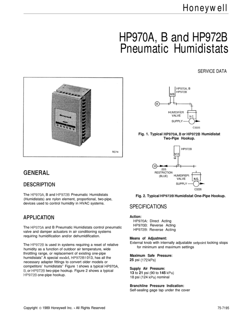
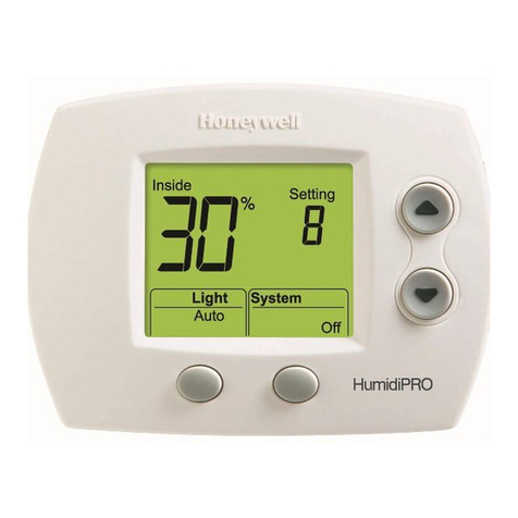
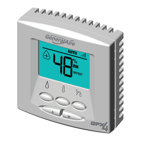
Honeywell HumidiPRO H6062 User manual

HumidiPRO H6062
Digital Humidity Control
Installation
Instructions

2
When Installing this Product
Read these instructions carefully, failure to follow them could damage the product and
cause a hazardous situation.
Check the ratings given in the instructions and on the product to make sure the
product is suitable for your application
Installer must be a trained, experienced service technician.
After installation is complete, check out product operation as provided in these
instructions.
Cautions
Electrical shock or equipment damage may occur.
Disconnect power supply before beginning installation.

3
Duct Installation (recommended) OR
1. Choose a location on the RETURN
duct.
Remote Mount Installation
1. Choose a location in the living area.
NOTE: Select a location clear of drafts
or excessive humidity. Avoid mounting
near doors or windows, or in bathrooms
or kitchens.
ALTERNATE
LOCATION
RETURN
AIR RETURN
AIR
6 IN (152 MM)
MINIMUM
15 IN (381 MM)
MINIMUM
BEST
LOCATION
RETURN
AIR DUCT M34579
YES NO
NO
M34567
Warning: Product must be mounted
on the RETURN side of the duct for
proper RH% sensing.

4
Duct-Mount Installation
2. Separate wallplate from humidistat.
-
3ETTING
,IGHT
!UTO . EXT!UTO
3YSTEM
2EPLACE"ATT
)NSIDE
(5-)$)49"//34
05,,(%2%
Caution: Electrical Hazard
Can cause electrical shock or equipment damage.
Disconnect power before beginning installation.
3. Mark the duct-tube hole.
Hold the wallplate up to the desired
location on the duct and make a mark
inside the duct tube hole.
M34580

5
4. Drill the duct-tube hole.
Find your mark and drill a 1/2 in. hole in
the duct. This is where the duct tube will
be inserted to capture air.
M34581
5. Insert the duct tube.
M34671
Insert the duct tube through
the wallplate before securing
to the duct.

6
6. Secure the wallplate.
M34582
M34610
RUN WIRES
THROUGH THE
TOP OR BOTTOM
CHANNEL
C
R
U
U
S
S
Secure the wallplate to the duct with
sheet metal screws (provided).
7. Run wires through the back plate.
Run wires through the top or bottom
channel on the back plate when duct-
mounted. If installing like a thermostat on
a wall, run the wires through the back.

7
Wiring the Humidistat
This humidity control is wired the same way a manual humidistat (H8908) is wired. The
only difference is that you also wire in power (24 VAC) and an outdoor sensor.
M34569
TERMINAL DESIGNATION
C 24 VAC POWER FROM EQUIPMENT
R 24 VAC POWER FROM EQUIPMENT
U HUMIDIFIER/DEHUMIDIFIER
S OUTDOOR SENSOR
S OUTDOOR SENSOR
NOTES: C AND R MUST BE CONSTANT 24VAC! RECOMMENDED TO WIRE TO
FURNACE/AIR HANDLER CONTROL BOARD.
DO NOT WIRE C AND R TO HUMIDIFIER TRANSFORMER!
C
R
U
U
S
S
24 VAC (CONSTANT)
TO HUMIDIFIER
OR DEHUMIDIFIER
OUTDOOR
TEMPERATURE
SENSOR

8
Wiring HumidiPRO with Fan Interlock
M34570
1
TRANSFORMER
FURNACE
FAN
MOTOR
FAN CONTROL
L1
(HOT)
L2
POWER
SUPPLY
1
2
PROVIDE DISCONNECT MEANS AND
OVERLOAD PROTECTION AS REQUIRED.
24 VAC WIRING.
HUMIDIFIER
2
C
R
U
U
S
S
24 VAC (CONSTANT)
OUTDOOR SENSOR

9
Wiring HumidiPRO with Fan Interlock for 2 Speed Motor
M34571
1
TRANSFORMER
2-SPEED
FAN MOTOR
FAN CONTROL
L1
(HOT)
L2
POWER
SUPPLY
1
2
PROVIDE DISCONNECT MEANS AND OVERLOAD PROTECTION AS REQUIRED.
24 VAC WIRING.
HUMIDIFIER
2
C
R
U
U
S
S
24 VAC (CONSTANT)
OUTDOOR SENSOR
DPST
SWITCHING
RELAY
HL
C

10
Wiring HumidiPRO with Current Sensing Relay
M34572
1
L1
(HOT)
L2
1PROVIDE DISCONNECT MEANS AND OVERLOAD PROTECTION AS REQUIRED.
HUMIDIFIER
C
R
U
U
S
S
24 VAC (CONSTANT)
OUTDOOR SENSOR
CURRENT
SENSING
RELAY
CHI
LO

11
Wiring HumidiPRO with Sail/Pressure Switch
M34573
1
L1
(HOT)
L2
1PROVIDE DISCONNECT MEANS AND OVERLOAD PROTECTION AS REQUIRED.
HUMIDIFIER
C
R
U
U
S
S
24 VAC (CONSTANT)
OUTDOOR SENSOR
AIR PRESSURE
SWITCH/SAIL
SWITCH

12
Wiring HumidiPRO to FORCE FAN ON (Basic Humidifier)
M34574
1
L1
(HOT)
L2
HUMIDIFIER
C
R
U
U
S
S
24 VAC (CONSTANT)
OUTDOOR SENSOR
DPST RELAY
R
C
W
Y
G
13
46
2
5
NOTES: USE DPST RELAY FOR HUMIDITY ON DEMAND
WITH A BASIC HUMIDIFIER.
HUMIDIFIER MUST BE PLUMBED TO HOT WATER
WHEN FORCING FAN.
HONEYWELL ADVANCED HUMIDIFIERS DO NOT
NEED A RELAY TO FORCE FAN.

13
Wiring HumidiPRO to TrueEASE Advanced Humidifier
with Fan Interlock (HE150/HE250/HE300)
M34577
NOTE: SEE TrueEASE INSTALL GUIDE FOR DETAILED WIRING INFORMATION.
HumidiPRO
C
R
U
U
S
S
HVAC
GYWR C
THERMOSTAT
G “FAN”
24VAC
CONSTANT
POWER IN
NOT REQUIRED
ON HE300
OUTDOOR
SENSOR

14
Wiring HumidiPRO to TrueSTEAM Advanced Humidifier
M34576
NOTE: SEE TrueSTEAM INSTALL GUIDE FOR DETAILED WIRING INFORMATION.
HumidiPRO
OUTDOOR SENSOR
R
C
W
Y
G
HVAC
24V
24V
HUM
HUM
C
GT
R
RT
GF
EXT
C
R
U
U
S
S
THERMOSTAT
G “FAN”
ON
OFF
1
AFS MONITOR RECOMMENDED
236
45

15
Wiring HumidiPRO to Dehumidifier
M34595
C
R
U
U
S
S
24 VAC
(CONSTANT)
RFloat DHUM FanC

16
Mounting the Outdoor Sensor
(Not required if window protection isn’t needed)
Location
Mount the sensor where:
• it cannot be tampered with.
• there is good air circulation.
• surface is flat.
• wire distance between sensor and humidistat is less than 200 feet.
• it can measure true outdoor ambient temperature.
Do NOT mount the sensor:
• in direct sunlight.
• where snow, ice or debris can cover it.
• where hot or cold air blows on the sensor. (For example, a discharge line from
an outdoor compressor unit, vent or fan can cause inaccurate temperature
readings.)

17
Steps to mount the sensor
1. Remove the sensor from the mounting
clip.
2. Mark the area on the location selected
for mounting the sensor mounting clip.
3. Mount the clip. Image on right shows
typical locations for outdoor sensor.
M7514A

18
Wiring the sensor
Caution
Electrical Interference (Noise) Hazard. Can cause erratic system operation.
• Keep wiring at least one foot away from large inductive loads such as motors,
line starters, lighting ballasts and large power distribution panels.
Use shielded cable to reduce interference when rerouting is not possible.
• Be sure wires have a cable separate from the thermostat cable.
• Do not route temperature sensor wiring with building power wiring, next to control
contactors or near light dimming circuits, electric motors or welding equipment.
• Avoid poor wiring connections.
• Avoid intermittent or missing building earth ground.

19
Caution
Electrical Shock Hazard. Can cause
electrical shock or equipment damage.
Disconnect power supply before connecting wiring.
Wiring must comply with applicable
codes, ordinances and regulations:
1. Wire the C7089 Outdoor Sensor to the
S terminals on the humidity control. If
leadwire provided with C7089 is not
long enough (60 in.), run a cable to a
hole at C7089 location.
• Using color-coded, 18-gauge,
shielded thermostat wire is
recommended. For example of
general wiring of C7089, see image
at right.
• Pigtail wiring can be used.
2. Mount C7089 in its mounting clip.
3. Plug wiring hole using nonhardening
caulk or putty.
1
2
2
1
USE APPROPRIATE MOUNTING MEANS FOR THE
TYPE OF STRUCTURE.
PLUG WIRING HOLE WITH NON-HARDENING
CAULK OR PUTTY.
C7089
WIRING HOLE
THROUGH
STRUCTURE
M34611
C
R
U
U
S
S

20
Mount Humidity
Control
Align the 4 tabs on the
wallplate with the slots on the
back of the control, then push
gently until the control snaps
in place.
TABS
TABS
WALLPLATE
M34583
SLOTS ON
BACK OF
HumidiPRO
Other manuals for HumidiPRO H6062
2
Table of contents
Languages:
Other Honeywell Humidistat manuals

Honeywell
Honeywell H8908B Humidistat User manual

Honeywell
Honeywell HP970A Mounting instructions
Honeywell
Honeywell HumidiPRO H6062 User manual

Honeywell
Honeywell H8908B Humidistat User manual
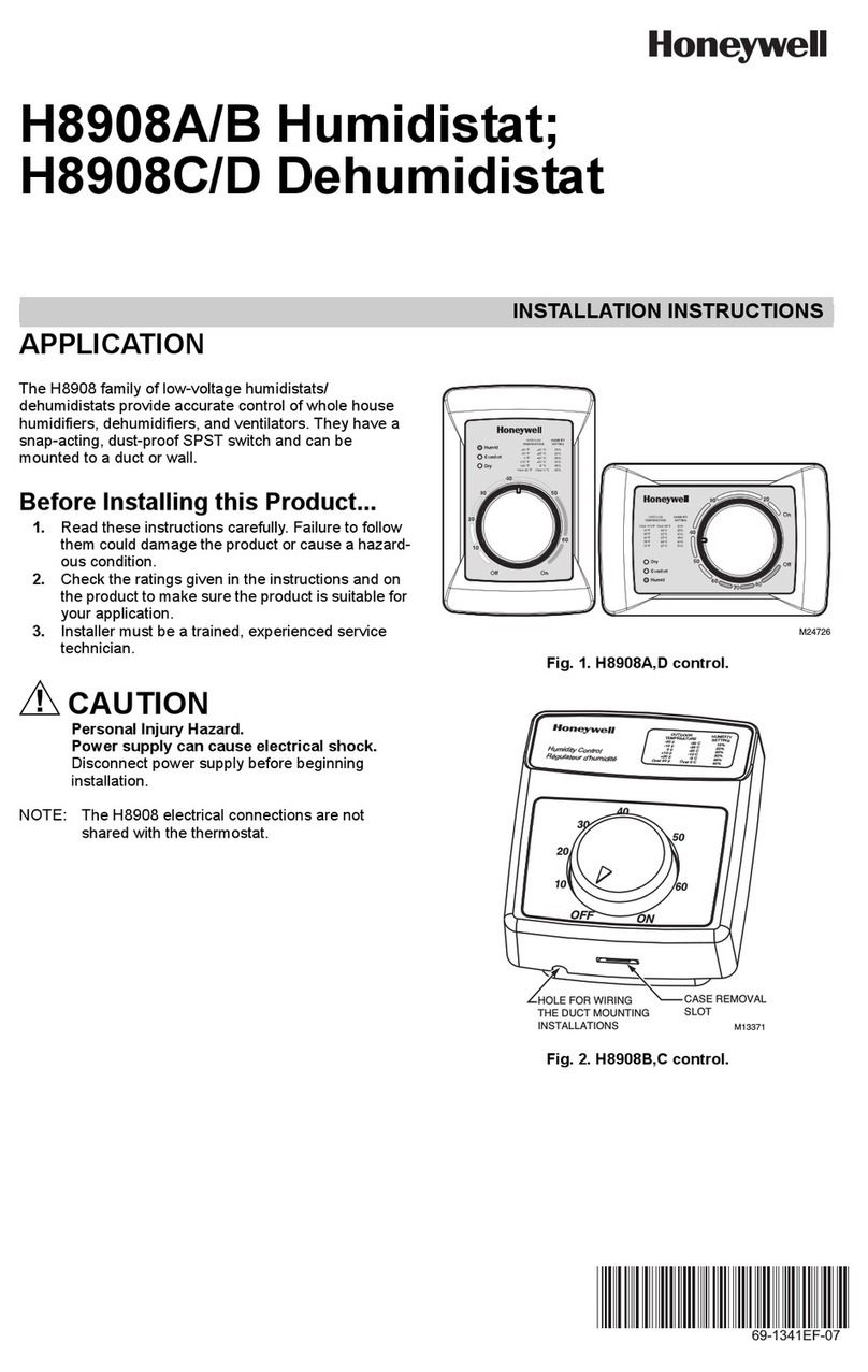
Honeywell
Honeywell H8908A/B User manual
Honeywell
Honeywell H8908ASPST - Humidistat Control User manual

Honeywell
Honeywell HumidiPRO H6062 User manual