Regin ED-RUD-2 Series User manual

EN INSTRUCTION
ED-RUD-2 ...
IN20055 REV. C, 2022-03-17
CCaauuttiioonn!! Read and understand t e instruction before using t e product.
CCaauuttiioonn!! Ensure t at t e installation complies wit local safety
regulations.
CCaauuttiioonn!! Before installation or maintenance, t e power supply s ould first
be disconnected. Installation or maintenance of t is unit s ould only be
carried out by qualified personnel. T e manufacturer is not responsible
for any eventual damage or injury caused by inadequate skills during instal-
lation, or t roug removal of or deactivation of any security devices.
Function
ED-RUD-2 ... is a slim flush or wall mounted room unit with backlit
touch screen. It is easy to use and works together with any Modbus
master controller. It can be used as Plug'n Play with Regin's room
controllers Regio rdo and RegioEedo and is prepared for easy configuration
with Regin's ventilation controllers Corrigo rdo and CorrigoVido.
Tec nical Data
Supply voltage 24 V AC/DC (22…26 V AC/DC)
Power consumption 60 mA
Protection class IP30
Ambient humidity 10…90 % RH (non-condensing)
Ambient temperature 0…50 °C
Storage temperature -20…+70 °C
Cable connection Terminal block, push-in. Max. 1.5 mm2(AWG 16)
Mounting Room (flush-mounted with screw distance cc 60
mm)
Display Built-in
Display type LED-backlit LCD
Dimensions, external
(WxHxD)
95 x 95 x 23 mm
Serial port 1
Port type RS485
Supported protocol Modbus (RTU)
Communication speed 38400 bps (4800…38400 bps)
Parity Even (Even, Odd, None)
Stop bit 1 (1 or 2)
Installation
The room unit is installed indoors on a back plate. ED-RUD-2 ...The
back plate is not included in the package and comes separately. There are
two different back plates available: one for flush mounting on an EU
standard wall mounting box (ED-RUD-2-FM) and one for mounting
directly on a wall (ED-RUD-2-WM).
The display is pre-configured for Plug'n Play use together with Regin 's
room controllers Regio rdo and RegioEedo.
For other controllers, the communication settings might need to be
changed in the Firmware configuration menu (see Handling).
If there are communication problems when using the display with
Corrigo rdo and CorrigoVido controllers, check the Configuration settings
for the Corrigo.
Wiring
Depending on the used controller there are two different wiring options:
–Option 1: The room unit is connected via a EDSP-K3 cable to the
controller's display port.
–Option 2: The room unit is connected to the controller's serial port.
The supply voltage is connected to the same supply voltage as the
controller (G and G0).
Terminal EDSP-K... wire color Description
+24 V Black Supply voltage, G
N White Supply voltage, G0
Terminal EDSP-K... wire color Description
B Brown Serial communication port, Com B
A Yellow Serial communication port, Com A
Wiring according to option 1
Figure 1 Communication via EDSP-K… (1=Black, 2=White, =Brown, 4=Yellow)
Wiring according to option 2
Figure 2 Communication via the serial port
Handling
The display consists of segments and buttons that all can be controlled
individually via the Modbus master. Regardless if the display is
connected to a master controller or not it is always possible to configure
communication parameters in the display:
1. Power up the display and press the On/Off button for 5 seconds
while in Power up sequence or press the down arrow and up arrow
button simultaneously for 5 seconds when in Running mode. Then
press the down arrow button twice
2. Navigate in the Firmware configuration menu with the arrow
buttons
3. Press the On/Off button to select a parameter. Use the arrows to
adjust the value. lways confirm with the On/Off button.
4. t the end of the menu the word EXIT appears in the display. To
exit the menu press the On/Off button when in EXIT.
NNoottee!! After c anging parameters, make sure to ave t e power on at
least 5 s to ensure t at t e values are stored correctly.
ED-RUD
+24 V
N
B
A
1
2
3
4EDSP-K3
+ 24 V
N
B
A
ED-RUD
ED-RUD-2 ... 1 (7)

Table 1 Firmware configuration parameters
Parameter Description Default
1 The Modbus Address the controller uses
1…254
1
2 Modbus stop bits and Parity
0 = 8N2
1 = 8O1
2 = 8E1
3 = 8N1
2
3 Modbus Time Out
At least 1.5 times a character
min = 2 ms (at 9 600 baud)
3
4 Modbus Answer delay
At least 3.5 times a character
min = 5 ms (at 9 600 baud)
5
5 Modbus baud rate
0 = 4800 bps
1 = 9600 bps
2 = 19200 bps
3 = 38400 bps
3
6 Intensity Active
Brightness of display when in Active or Setpoint
mode
0…100 %
100 %
7 Intensity Idle
Brightness of display when in Idle mode
0…100 %
25 %
8 Idle timeout
Time to change from Active to Idle
5…600 s
20 s
9 Calibration of internal temperature sensor
Used to correct the internal temperature read-
ing if necessary
-10°C…+10°C
Scale 0.1
0.0
For more information regarding the configuration of the buttons and
segments as well as the available Modbus variables, see the document
Variable list ED-RUD-2 ....
This product carries the CE-mark. More information is available at
www.regincontrols.com.
Contact
B Regin, Box 116, 428 22 Kållered, Sweden
Tel: +46 31 720 02 00, Fax: +46 31 720 02 50
www.regincontrols.com, [email protected]
SE INSTRUKTION
ED-RUD-2 ...
OObbsseerrvveerraa!! Läs oc förstå instruktionen innan du använder produkten.
OObbsseerrvveerraa!! Se till att installationen uppfyller lokala
säker etsbestämmelser.
OObbsseerrvveerraa!! Innan installation eller under åll måste matningsspänningen
först kopplas från. Installation eller under åll av denna en et ska endast ut-
föras av kvalificerad personal. Tillverkaren är inte ansvarig för eventuella
skador som orsakas av felaktig installation oc /eller inaktivering eller bort-
tagning av säker etsanordningar.
Funktion
ED-RUD-2 ... är en tunn rumsenhet för vägg- eller infällt montage med
bakgrundsbelyst touchdisplay. Den är enkel att använda och fungerar
tillsammans med valfri Modbus-masterregulator. Den kan användas för
Plug'n Play med Regins rumsregulatorer Regio rdo och RegioEedo och är
förberedd för enkel konfigurering med Regins ventilationsregulatorer
Corrigo rdo och CorrigoVido.
Tekniska data
Matningsspänning 24 V AC/DC (22…26 V AC/DC)
Strömförbrukning 60 mA
Skyddsklass IP30
Omgivande luftfuktighet 10...90 % RH (icke-kondenserande)
Omgivningstemperatur 0…50 °C
Lagringstemperatur -20…+70 °C
Kabelanslutning Push-in-plint Max. 1,5 mm2(AWG 16)
Montering Rum (inbyggt montage med skruvavstånd cc 60
mm)
Display Inbyggd
Typ av display Bakgrundsbelyst LCD
Dimensioner, yttre
(BxHxD)
95 x 95 x 23 mm
Serieport 1
Porttyp RS485
Stödda protokoll Modbus (RTU)
Kommunikationshastig-
het
38400 bps (4800…38400 bps)
Paritet Jämn (Jämn, Udda, Ingen)
Stoppbitar 1 (1 eller 2)
Installation
Rumsenheten installeras inomhus på en bakplatta. ED-RUD-2 ...
Bakplattan ingår inte utan kommer separat. Det finns två bakplattor
tillgängliga: en för infällt montage på en EU-standard väggdosa (ED-
RUD-2-FM) och en för montreing direkt på vägg (ED-RUD-2-WM).
Displayen är förkonfigurerad för Plug'n Play tillsammans med Regin 's
rumsregulatorer Regio rdo and RegioEedo.
När den används med andra regulatorer kan
kommunikationsinställningarna behöva ändras via Firmware-
konfigureringsmen n (se Hantering).
Om det uppstår kommunikationsproblem vid användning av displayen
med Corrigo rdo och CorrigoVido regulatorer, kontrollera
konfigureringsinställningarna för Corrigon.
Inkoppling
Det finns två olika inkopplingsmöjligheter beroende på vilken regulator
som används:
–Alternativ 1: Rumsenheten ar kopplad via en EDSP-K3-kabel till
regulatorns displayport.
–Alternativ 2: Rumsenheten ansluts till regulatorns seriella port.
Matningsspänningen kopplas till samma matningsspänning som
regulatorn (G och G0).
Plint EDSP-K… trådfärg Beskrivning
+24 V Svart Matningsspänning, G
N Vit Matningsspänning, G0
B Brun Seriell kommunikationsport, Com B
A Gul Seriell kommunikationsport, Com A
Inkoppling enligt alternativ 1
ED-RUD-2 ... 2 (7)

Figur 1 Kommunikation via EDSP-K… (1=Svart, 2=Vit, =Brun, 4=Gul)
Inkoppling enligt alternativ 2
Figur 2 Kommunikation via serieporten
Hantering
Displayen består av segment och knappar som alla kan kontrolleras
individuellt via Modbus mastern. Oberoende av om displayen är kopplad
till en master-regulator eller inte, är det alltid möjligt att konfigurera
kommunikationsparametrarna i displayen:
1. Starta displayen och tryck På/ v-knappen i 5 sekunder under
Uppstart-sekvensen, eller tryck på pil ned och pil upp knapparna
samtidigt i 5 sekunder när enheten är igång. Tryck sedan på pil ned
två gånger.
2. Navigera i Firmware-konfigureringsmenyn med pilknapparna
3. Tryck på På/ v-knappen för att välja en parameter. nvänd pilarna
för att ställa in värdet. Bekräfta alltid med Till/Från-knappen.
4. I slutet av menyn visas ordet EXIT i displayen. För att lämna menyn
tryck in På/ v-knappen i EXIT läge.
NNootteerraa!! Efter parametrar ar ändrats måste spänningen vara på minst 5 s
för att försäkra att värdena sparas på rätt sätt.
Tabell 1 Firmware-konfigureringsparametrar
Parameter Beskrivning Förinställt
1 Modbusadressen som regulatorn använder
1…254
1
2 Modbus stoppbitar och paritet
0 = 8N2
1 = 8O1
2 = 8E1
3 = 8N1
2
3 Modbus timeout
Minst 1,5 gånger ett tecken
min = 2 ms (vid 9600 baud)
3
4 Svarsfördröjning Modbus
Minst 3,5 gånger ett tecken
min = 5 ms (vid 9600 baud)
5
5 Modbus baud rate
0 = 4800 bps
1 = 9600 bps
2 = 19200 bps
3 = 38400 bps
3
6 Intensitet Aktiv
Ljusstyrka på displayen i Aktivt eller Börvärdes-
läge
0…100 %
100%
7 Intensitet Inaktiv
Ljusstyrka på displayen i inaktivt läge
0…100 %
25 %
8 Inaktiv timeout
Tid för ändring mellan Aktive och Inaktiv
5…600 s
20 s
9 Kalibrering av intern temperaturgivare
Används för att korrigera den interna tempera-
turläsningen om nödvändigt.
-10°C…+10°C
Skala 0,1
0,0
För mer information angående konfigurering av knapparna och
segmenten samt tillgängliga Modbus variabler, se dokumentet
Variabellista ED-RUD-2 ....
Produkten är CE-märkt. Mer information finns på www.regincontrols.
com.
Kontakt
B Regin, Box 116, 428 22 Kållered, Sverige
Tel: +46 31 720 02 00, Fax: +46 31 720 02 50
www.regincontrols.com, [email protected]
DE INSTALLATIONSANLEITUNG
ED-RUD-2 ...
VVoorrssiicc tt!! Lesen und beac ten Sie die Installationsanleitung, bevor Sie das
Produkt verwenden.
VVoorrssiicc tt!! Vergewissern Sie sic , dass die Installation den geltenden Si-
c er eitsvorsc riften entspric t.
VVoorrssiicc tt!! Vor der Installation oder Wartung muss zuerst die Stromver-
sorgung unterbroc en werden. Die Installation oder Wartung dieses Ge-
rätes darf nur von qualifizierten Fac kräften durc gefü rt werden. Der
Hersteller aftet nic t für eventuelle Sc äden oder Verletzungen, die
durc mangelnde Fac kenntnisse bei der Installation oder durc das Ent-
fernen bzw. Deaktivieren von Sic er eitsvorric tungen entste en.
Funktion
ED-RUD-2 ... ist ein flaches Raumgerät für die Unterputz- oder
Wandmontage mit hintergrundbeleuchtetem Touchscreen. Es ist
benutzerfreundlich und kann zusammen mit jedem Modbus-Master-
Regler eingesetzt werden. Es kann per Plug-and-Play mit den Regin
Raumreglern Regio rdo und RegioEedo eingesetzt werden und ist für eine
einfache Konfiguration mit den Regin Lüftungsreglern Corrigo rdo und
CorrigoVido vorbereitet.
Tec nisc e Daten
Versorgungsspannung 24 V AC/DC (22…26 V AC/DC)
Leistungsaufnahme 60 mA
Schutzart IP30
Umgebungsfeuchte 10...90 % RH (nicht kondensierend)
Umgebungstemperatur 0…50 °C
Lagertemperatur -20…+70 °C
Kabelanschluss Federkraftklemmen. Max. 1,5 mm2(AWG 16)
Montage Raum (Unterputz mit Schraubenabstand ca.
60 mm)
Display Integriert
Display-Typ LCD mit LED-Hintergrundbeleuchtung
Abmessungen, außen (B
x H x T)
95 x 95 x 23 mm
ED-RUD
+24 V
N
B
A
1
2
3
4EDSP-K3
+ 24 V
N
B
A
ED-RUD
ED-RUD-2 ... 3 (7)

Serielle Schnittstelle 1
Schnittstellentyp RS485
Unterstütztes Protokoll Modbus (RTU)
Kommunikationsge-
schwindigkeit
38400 bps (4800…38400 bps)
Parität Gerade (Gerade, Ungerade, Keine)
Stoppbit 1 (1 oder 2)
Installation
Das Raumgerät wird in Innenräumen auf einer Montageplatte installiert.
ED-RUD-2 ...Die Montageplatte ist nicht im Lieferumfang enthalten
und muss separat bestellt werden. Es sind folgende zwei Montageplatten
verfügbar: für die Unterputzmontage auf einer EU-genormten
Wandunterputzdose (ED-RUD-2-FM) oder für die Montage direkt an
der Wand (ED-RUD-2-WM).
Das Display ist für die Verwendung per Plug-and-Play zusammen mit
Regin s Raumreglern Regio rdo und RegioEedo vorkonfiguriert.
Für andere Regler müssen eventuell die Kommunikationseinstellungen
im Firmware-Konfigurationsmenü (siehe Bedienung) geändert werden.
Falls es bei der Verwendung des Displays mit den Reglern Corrigo rdo
und CorrigoVido zu Kommunikationsproblemen kommt, prüfen Sie bitte
die Einstellungen der Konfiguration für den Corrigo.
Verdra tung
bhängig vom verwendeten Regler gibt es zwei Möglichkeiten der
Verdrahtung:
–Option 1: Das Raumgerät wird mit dem Kabel EDSP-K3 an den
Display- nschluss des Reglers angeschlossen.
–Option 2: Das Raumgerät wird an die serielle Schnittstelle des
Reglers angeschlossen. Die Versorgungsspannung wird an die
gleiche Versorgungsspannung wie der Regler angeschlossen (G und
G0).
Klemme EDSP-K... Aderfarbe Beschreibung
+24 V Schwarz Versorgungsspannung, G
N Weiß Versorgungsspannung, G0
B Braun Serielle Kommunikationsschnittstelle,
Com B
A Gelb Serielle Kommunikationsschnittstelle,
Com A
Verdrahtung gemäß Option 1
Bild 1 Kommunikation über EDSP-K...(1=Schwarz, 2=Weiß, =Braun, 4=Gelb)
Verdrahtung gemäß Option 2
Bild 2 Kommunikation über serielle Schnittstelle
Bedienung
Das Display ist in Segmente und Tasten unterteilt, die alle einzeln über
den Modbus-Master gesteuert werden können. Unabhängig davon, ob
das Display an einen Hauptregler (Master) angeschlossen ist oder nicht,
ist die Konfiguration der Kommunikationsparameter im Display immer
möglich:
1. Schalten Sie das Display ein und drücken Sie während der
Einschaltphase 5 Sekunden lang die Ein/ us-Taste oder halten Sie im
Betriebsmodus die Pfeil-nach-unten-Taste und die Pfeil-nach-oben-
Taste gleichzeitig 5 Sekunden lang gedrückt. Drücken Sie dann
zweimal die Pfeil-nach-unten-Taste.
2. Navigieren Sie mit den Pfeiltasten im Firmware-
Konfigurationsmenü.
3. Drücken Sie die Ein/ us-Taste, um einen Parameter auszuwählen.
Verwenden Sie die Pfeiltasten, um den Wert einzustellen. Bestätigen
Sie immer mit der Ein/ us-Taste.
4. m Ende des Menüs erscheint auf dem Display das Wort EXIT.
Drücken Sie die Ein/ us-Taste, wenn Sie sich in EXIT befinden, um
das Menü zu verlassen.
HHiinnwweeiiss!! Ac ten Sie nac der Änderung von Parametern darauf, dass der
Strom noc mindestens 5 Sekunden lang eingesc altet ist, um sic erzu-
stellen, dass die Werte korrekt gespeic ert werden.
Tabelle 1 Konfigurationsparameter der Firmware
Parameter Beschreibung Voreinstel-
lung
1 Die vom Regler verwendete Modbus-Adresse
1…254
1
2 Modbus-Stoppbits und Parität
0 = 8N2
1 = 8O1
2 = 8E1
3 = 8N1
2
3 Modbus-Zeitüberschreitung
Mindestens das 1,5-fache der Zeichen
min. = 2 ms (bei 9600 baud)
3
4 Modbus-Antwortverzögerung
Mindestens das 3,5-fache der Zeichen
min. = 5 ms (bei 9600 baud)
5
5 Modbus-Baudrate
0 = 4800 bps
1 = 9600 bps
2 = 19200 bps
3 = 38400 bps
3
6 Intensität Aktiv
Helligkeit des Displays im Modus Aktiv oder
Sollwert
0…100 %
100 %
7 Intensität Standby
Helligkeit des Displays im Modus Standby
0…100 %
25 %
8 Standby-Zeitüberschreitung
Zeit bis zum Wechsel von Aktiv zu Standby
5…600 s
20 s
9 Kalibrierung des internen Temperaturfühlers
Ermöglicht bei Bedarf die Korrektur der internen
Temperaturmessung.
-10 °C…+10 °C
Skala 0,1
0,0
Weitere Informationen zur Konfiguration der Tasten und Segmente
sowie zu den verfügbaren Modbus-Variablen finden Sie im Dokument
VariablenlisteED-RUD-2 ....
Dieses Produkt trägt das CE-Zeichen. Weitere Informationen finden Sie
unter www.regincontrols.de.
ED-RUD
+24 V
N
B
A
1
2
3
4EDSP-K3
+ 24 V
N
B
A
ED-RUD
ED-RUD-2 ... 4 (7)

Kontakt
Regin Controls Deutschland GmbH, Haynauer Str. 49, 12249 Berlin,
Deutschland
Tel: +49 30 77 99 4-0, Fax: +49 30 77 99 4-13
www.regincontrols.de, [email protected]
FR INSTRUCTION
ED-RUD-2...
AAtttteennttiioonn !! Veuillez lire attentivement les instructions avant d’utiliser le
produit.
AAtttteennttiioonn !! Assurez-vous que l’installation est conforme aux normes de
sécurité locales.
AAtttteennttiioonn !! Avant de procéder à l’installation ou à la maintenance de l’ap-
pareil, il convient de couper l’alimentation électrique. Les opérations d’ins-
tallation et de maintenance doivent être effectuées par un professionnel
qualifié. Le fabricant ne pourra être tenu responsable d’éventuels domma-
ges ou blessures causés par une installation défectueuse du produit, ou
par la désactivation des dispositifs de sécurité.
Fonctionnement
ED-RUD-2... Unité d’ambiance mince, encastrée ou montée au mur,
avec écran tactile rétroéclairé. Le système est facile à utiliser et est
compatible avec tout régulateur Modbus maître. Il peut être utilisé
comme écran Plug’n Play avec les régulateurs d’ambiance Regio rdo et
RegioEedo de Regin et est conçu pour une configuration facile avec les
régulateurs de ventilation Corrigo rdo et CorrigoVido.
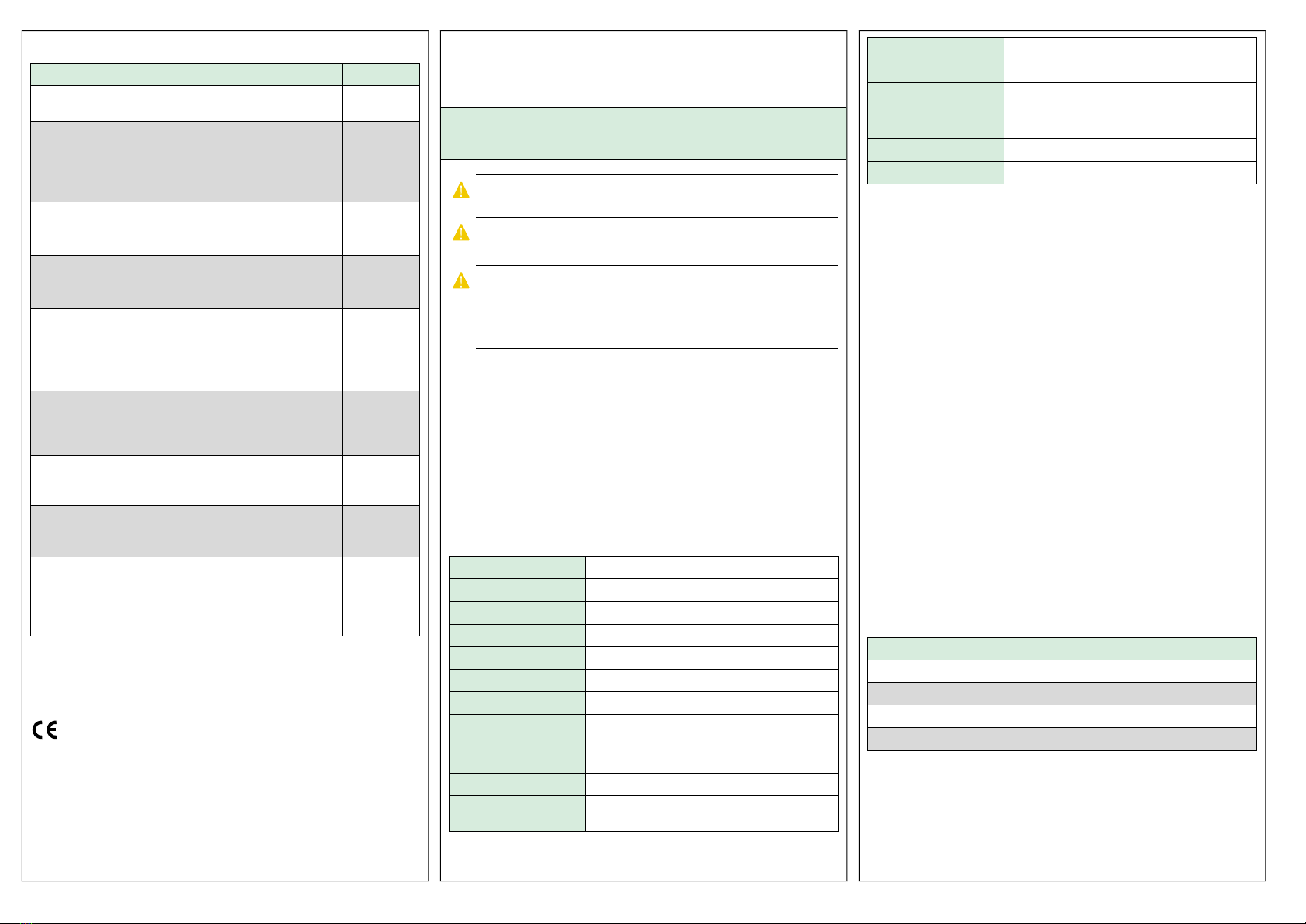
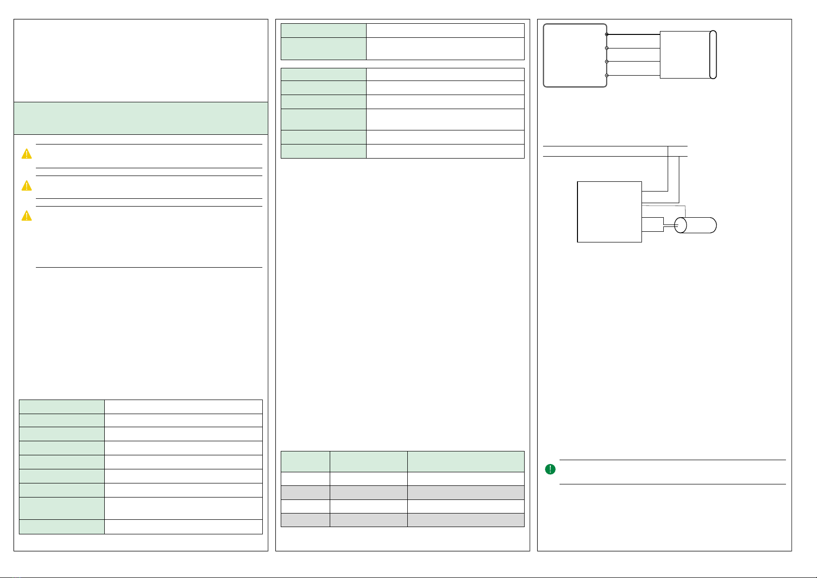
Caractéristiques tec niques
Tension d’alimentation 24 V AC/DC (22…26 V AC/DC)
Puissance consommée 60 mA
Indice de protection IP30
Humidité ambiante 10...90 % HR (sans condensation)
Température ambiante 0…50 °C
Température de stockage -20…+70 °C
Raccordement Bornier, enfichable. Max. 1,5 mm2(AWG 16)
Montage Unité d’ambiance (montage encastré avec une dis-
tance entre les vis de 60 mm)
Écran Intégré
Type d’écran LCD, rétroéclairé par LED
Dimensions, externes
(LxHxP)
95 x 95 x 23 mm
Port série 1
Type de port RS485
Protocoles supportés Modbus RTU
Vitesse de
communication
38400 bps (4800…38400 bps)
Parité Paire (Paire, Impaire, Aucune)
Bits de stop 1 (1 ou 2)
Installation
L’unité d’ambiance est installée à l’intérieur sur une platine de fixation.
ED-RUD-2...Cette platine n’est pas incluse dans le colis et peut être
livrée séparément. Il existe deux formats de platines : une pour un
montage encastré dans un boîtier en montage mural aux normes
européennes (ED-RUD-2-FM) et une pour un montage au mur direct
(ED-RUD-2-WM).
L’écran est préconfiguré pour une utilisation plug-and-play avec les
Regin régulateurs d’ambiance Regio rdo et RegioEedo.
Pour les autres régulateurs, il peut être nécessaire de modifier les
paramètres de communication dans le menu de configuration du
micrologiciel (voir Fonctionnement).
Si vous rencontrez des problèmes de communication avec les écrans des
régulateurs Corrigo rdo et CorrigoVido, vérifiez les paramètres de
Configuration du Corrigo.
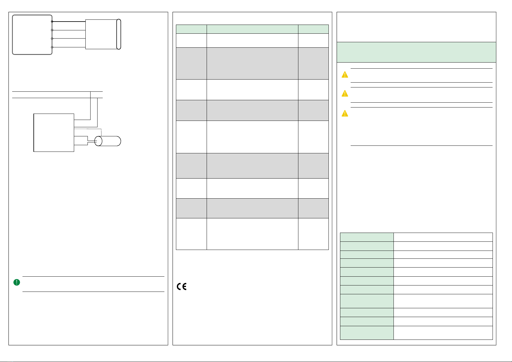
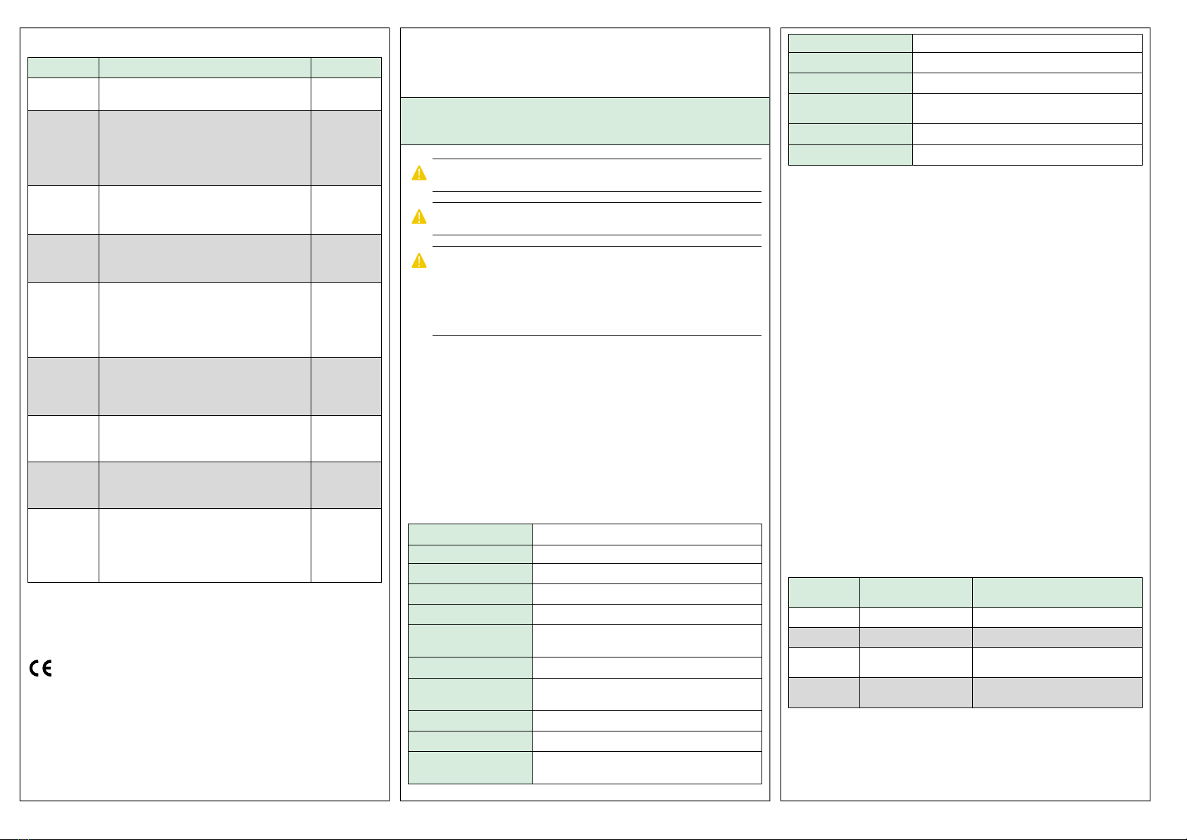
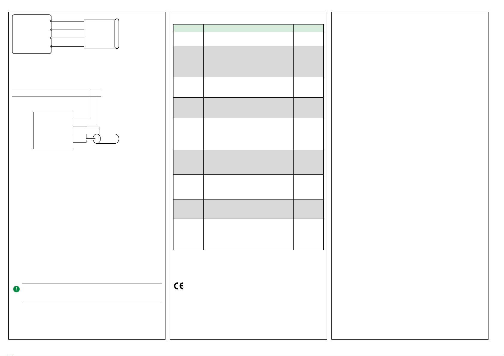
Raccordement
Selon le régulateur utilisé, il existe deux options de raccordement :
– Option 1 : L’unité d’ambiance est raccordée via un câble EDSP-K3
au port-écran du régulateur
– Option 2 : L’unité d’ambiance est connectée au port de
communication du régulateur. L’alimentation est connectée aux
mêmes bornes que l’alimentation du régulateur (G et G0).
Borne Couleurs des fils
EDSP-K3
Description
+24 V Noir Tension d’alimentation, G
N Blanc Tension d’alimentation, G0
B Marron Port série de communication, Com B
A Jaune Port série de communication, Com A
Raccordement selon l’option 1
Fig. 1 Communication via EDSP-K… (1=Noir, 2=Blanc, =Marron, 4=Jaune)
Raccordement selon l’option 2
Fig. 2 Communication via le port série
Fonctionnement
L’afficheur est composé de segments et de boutons pouvant être
contrôlés individuellement en Modbus maître. Que l’écran soit connecté
à un régulateur maître ou pas, il est toujours possible de configurer les
paramètres de communication via l’écran.
1. Mettez l’écran sous tension et appuyez sur le bouton On/Off
pendant 5 secondes pendant la séquence de mise sous tension ou
appuyez simultanément sur la flèche vers le bas et la flèche vers le
haut pendant 5 secondes en mode actif. Ensuite, appuyez deux fois
sur la flèche vers le bas
2. Naviguer dans le menu de configuration avec les flèches
3. ppuyer sur le bouton on/Off pour sélectionner un paramètre.
Utiliser les flèches pour ajuster un paramètre. Toujours confirmer
avec On/Off.
4. la fin du menu, le mot EXIT apparaît sur l’écran. Pour sortir du
menu appuyer sur On/Off lorsque l’écran indique EXIT.
NNBB !! Après un c angement de paramètre, bien s’assurer que l’écran reste
alimenté au moins 5 secondes pour que la mémoire soit écrite.
ED-RUD
+24 V
N
B
A
1
2
3
4EDSP-K3
+ 24 V
N
B
A
ED-RUD
ED-RUD-2 ... 5 (7)

Tableau 1 Paramètres de configuration du micrologiciel
Paramètre Description Défaut
1 L’adresse Modbus utilisée par le régulateur
1…254
1
2 Bits d’arrêt et de parité Modbus
0 = 8N2 (aucune parité avec 2 bits d’arrêt)
1 = 8O1 (aucune parité avec 2 bits d’arrêt)
2 = 8E1 (aucune parité avec 2 bits d’arrêt)
3 = 8N1 (aucune parité avec 2 bits d’arrêt)
2
3 Time Out Modbus
Doit être égal à 1,5 fois un caractère
min = 2 ms (à 9 600 bauds)
3
4 Délai de réponse Modbus
Doit être égal à 3,5 fois un caractère
min = 5 ms (à 9 600 bauds)
5
5 Taux de transmission Modbus
0 = 4 800 bps
1 = 9 600 bps
2 = 19 200 bps
3 = 38 400 bps
3
6 Intensité Actif
Luminosité de l'affichage en mode Actif ou
Point de consigne
0…100 %
100 %
7 Intensité Inactif
Luminosité de l’affichage en mode Inactif
0…100 %
25 %
8 Délai de mise en veille
Délai de passage de Actif àEn veille
5…600 s
20 s
9Étalonnage de la sonde de température interne
Permet de corriger la lecture de la température
interne si nécessaire
-10°C... +10°C
Échelle 0,1
0,0
Pour plus d’informations concernant la configuration des boutons et des
segments ainsi que des variables Modbus, voir Liste de variables ED-
RUD-2....
Ce produit porte le marquage CE. Pour plus d'information, veuillez
consulter le site web www.regincontrols.com.
Contact
Regin France, 32 rue Delizy, Hall 3, 93500 Pantin
Tél. : +33(0)1 41 83 02 02, Fax : +33(0)1 57 14 95 91
www.regin.fr, [email protected]
IT ISTRUZIONI PER L'INSTALLAZIONE
ED-RUD-2...
AAtttteennzziioonnee Prima di utilizzare il prodotto, leggere e comprendere le
istruzioni.
AAtttteennzziioonnee Assicurarsi c e l'installazione sia conforme alle norme di sicu-
rezza locali.
AAtttteennzziioonnee Prima dell'installazione o della manutenzione, l'alimentazione
deve essere scollegata per evitare scosse elettric e potenzialmente letali!
L'installazione o la manutenzione dell'unità deve essere eseguita solo da
personale qualificato. Il produttore non è responsabile di eventuali danni o
lesioni provocati da imperizia durante l'installazione o dalla rimozione o di-
sattivazione dei dispositivi di sicurezza.
Funzione
ED-RUD-2... è un' ambiente da incasso o da parete con touch display
retroilluminato. È facile da usare e funziona insieme a qualsiasi
controllore Modbus master. Può essere utilizzato Plug'n Play con i
controllori d'ambiente di Regin Regio rdo e RegioEedo ed è predisposto
per una facile configurazione con i controllori di ventilazione di Regin
Corrigo rdo e CorrigoVido.
Caratteristic e tecnic e
Alimentazione 24 V AC/DC (22…26 V AC/DC)
Potenza assorbita 60 mA
Grado di protezione IP30
Umidità ambiente 10...90 % UR (senza condensa)
Temperatura ambiente 0…50 °C
Temperatura di
stoccaggio
-20…+70 °C
Cavo per connessione Morsettiera, a innesto. Max. 1,5 mm2(AWG 16)
Montaggio Ambiente (montaggio a incasso con distanza tra le
viti di 60 mm)
Display Integrato
Tipo di display LCD con retroilluminazione a LED
Dimensioni, esterne
(LxPxA)
95 x 95 x 23 mm
Porta seriale 1
Tipo di porta RS485
Protocollo supportato Modbus RTU
Velocità di
comunicazione
38400 bps (4800…38400 bps)
Parità Pari (Pari, Dispari, Nessuna)
Bit di stop 1 (1 o 2)
Installazione
L'unità ambiente è installata all'interno su una staffa posteriore. ED-
RUD-2...Questa non è inclusa nella confezione e viene fornita
separatamente. Sono disponibili due diverse staffe posteriori: una per il
montaggio a incasso su parete standard UE (ED-RUD-2-FM) e una per il
montaggio direttamente a parete (ED-RUD-2-WM).
Il display è preconfigurato per l'uso Plug'n Play insieme ai controllori
d'ambiente Regin Regio rdo e RegioEedo.
Se utilizzato con altri controllori, puo essere necessario modificare le
impostazioni di communicazione nel menu di configurazione del Firmware
(vedi Gestione).
Se si dovessero verificare problemi di comunicazione quando si utilizza il
display con i controllori Corrigo rdo e CorrigoVido controlla le
impostazioni di configurazione per il Corrigo.
Cablaggio
In base al controllore utilizzato ci sono due diverse opzioni di cablaggio:
–Opzione 1: L'unità ambiente è collegata tramite un cavo EDSP-K3
alla porta display del controllore.
–Opzione 2: L'unità ambiente è collegata alla porta seriale del
controllore. La tensione di alimentazione è collegata alla stessa
tensione di alimentazione del controllore (G e G0).
Morsetto Colore del filo EDSP-
K…
Descrizione
+24 V Nero Tensione di alimentazione, G
N Bianco Tensione di alimentazione, G0
B Marrone Porta di comunicazione seriale, Com
B
A Giallo Porta di comunicazione seriale, Com
A
Ca laggio come da opzione 1
ED-RUD-2 ... 6 (7)

Fig. 1 Comunicazione tramite EDSP-K… (1=Nero, 2=Bianco, =Marrone, 4=Giallo)
Ca laggio come da opzione 2
Fig. 2 Comunicazione tramite porta seriale
Gestione
Il display si compone di segmenti e pulsanti che possono essere gestiti
singolarmente tramite Modbus master. Che il display sia collegato o no a
un controllore master, è sempre possibile configurare i parametri di
comunicazione sul display:
1. ccendere il display e premere il pulsante On/Off per 5 secondi
durante la sequenza di Accensione oppure premere
contemporaneamente i pulsanti freccia giù e freccia su per 5 secondi
quando in Modalità di esecuzione. Quindi premere due volte il
pulsante freccia giù.
2. Spostarsi nel menu Configurazione firmware con i pulsanti freccia.
3. Premere il pulsante On/Off per selezionare un parametro. Utilizzare
le frecce per impostare il valore. Confermare sempre con il pulsante
On/Off.
4. lla fine del menu sul display appare la parola EXIT. Per uscire dal
menu premere il pulsante On/Off quando è visualizzato EXIT.
NNoottaa!! Dopo aver modificato i parametri, lasciare acceso il dispositivo per
almeno 5 secondi, per assicurarsi c e i valori siano memorizzati
correttamente.
Tabella 1 Parametri di configurazione del firmware
Parametro Descrizione Predefinito
1 L'indirizzo Modbus utilizzato dal controllore
1…254
1
2 Bit di stop e parità Modbus
0 = 8N2
1 = 8O1
2 = 8E1
3 = 8N1
2
3 Timeout Modbus
Almeno 1,5 volte un carattere
min = 2 ms (a 9 600 baud)
3
4 Ritardo risposta Modbus
Almeno 3,5 volte un carattere
min = 5 ms (a 9 600 baud)
5
5 Baud rate Modbus
0 = 4800 bps
1 = 9600 bps
2 = 19200 bps
3 = 38400 bps
3
6 Intensità Attivo
Luminosità del display quando in modalità Atti-
vo oSetpoint
0…100 %
100%
7 Intensità Inattivo
Luminosità del display quando in modalità
Inattivo
0…100 %
25%
8 Timeout inattivo
Tempo per passare da Attivo aInattivo
5…600 s
20 s
9 Calibrazione del sensore di temperatura interno
Utilizzato per correggere la lettura della tempe-
ratura interna, se necessario
-10°C…+10°C
Scala 0,1
0,0
Per ulteriori informazioni sulla configurazione dei pulsanti e dei
segmenti, nonché sulle variabili Modbus disponibili, consultare il
documento Elenco variabili ED-RUD-2....
Questo prodotto è provvisto di marchio CE. Ulteriori informazioni sono
disponibili su www.industrietechnik.it
Contatti
B Industrietechnik SRL, Via Julius-Durst-Str.50, I-39042 Bressanone
(BZ)
Tel: +390472830626, Fax: +390472831840
www.industrietechnik.it, [email protected]
ED-RUD
+24 V
N
B
A
1
2
3
4EDSP-K3
+ 24 V
N
B
A
ED-RUD
ED-RUD-2 ... 7 (7)
Table of contents
Other Regin Humidistat manuals