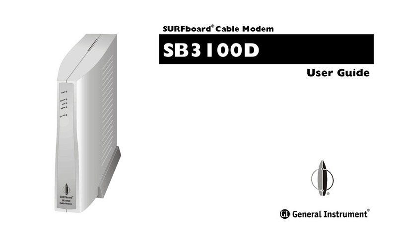
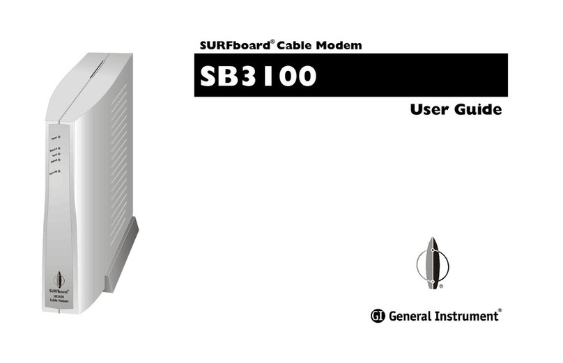
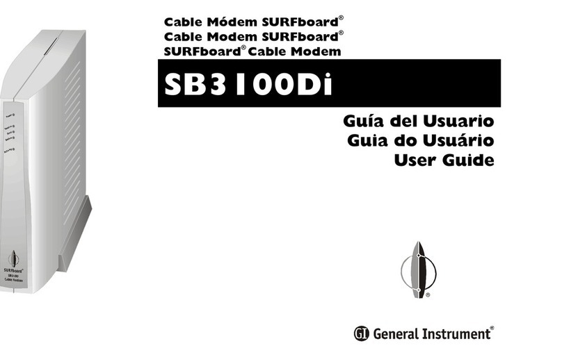
General Instrument SURFboard SB3100 User manual

SB3100
Cable Modem
Installation Manual
SURFboard®

:$51,1*
7235(9(17),5(256+2&.+$=$5''2127(;326(7+,6$33/,$1&(725$,12502,6785(
&$87,21
7235(9(17(/(&75,&$/6+2&.'212786(7+,63/8*:,7+$1(;7(16,21&25'5(&(37$&/(2527+(5287/(781/(667+(%/$'(6
&$1%()8//<,16(57('7235(9(17%/$'((;32685(
&DQDGLDQ&RPSOLDQFH
7KLV&ODVV%GLJLWDODSSDUDWXVPHHWVDOOUHTXLUHPHQWVRIWKH&DQDGLDQ,QWHUIHUHQFH&DXVLQJ(TXLSPHQW5HJXODWLRQV
&HWDSSDUHLOQXPpULTXHGHODFODVVH%UHVSHFWVWRXWHVOHVH[LJHQFHVGX5qJOHPHQWVXUOHPDWpULHOEURXLOOHXUGX&DQDGD
5HSDLUV
,IUHSDLULVQHFHVVDU\FDOOWKH*HQHUDO,QVWUXPHQW5HSDLU)DFLOLW\DWIRUD5HWXUQIRU6HUYLFH$XWKRUL]DWLRQ56$QXPEHUEHIRUH
VHQGLQJWKHXQLW7KH56$QXPEHUPXVWEHSURPLQHQWO\GLVSOD\HGRQDOOHTXLSPHQWFDUWRQV3DFNWKHXQLWVHFXUHO\HQFORVHDQRWHGHVFULELQJWKHH[DFW
SUREOHPDQGDFRS\RIWKHLQYRLFHWKDWYHULILHVWKHZDUUDQW\VWDWXV6KLSWKHXQLW35(3$,'WRWKHIROORZLQJDGGUHVV
*HQHUDO,QVWUXPHQW&RUSRUDWLRQ
$WWQ56$BBBBBBBBBBB
(
WK
6WUHHW
%URZQVYLOOH7;
127(72&$796<67(0,167$//(5
7KLVUHPLQGHULVSURYLGHGWRFDOO&$79V\VWHPLQVWDOOHU·VDWWHQWLRQWR$UWLFOHRIWKH1(&WKDWSURYLGHV
JXLGHOLQHVIRUSURSHUJURXQGLQJDQGLQSDUWLFXODUVSHFLILHVWKDWWKHFDEOHJURXQGVKDOOEHFRQQHFWHGWRWKHJURXQGLQJV\VWHPRIWKHEXLOGLQJDVFORVH
DVSRVVLEOHWRWKHSRLQWRIFDEOHHQWU\DVSUDFWLFDO
&RS\ULJKWE\*HQHUDO,QVWUXPHQW&RUSRUDWLRQ
$OOULJKWVUHVHUYHG1RSDUWRIWKLVSXEOLFDWLRQPD\EHUHSURGXFHGLQDQ\IRUPRUE\DQ\PHDQVRUXVHGWRPDNHDQ\GHULYDWLYHZRUNVXFKDVWUDQVODWLRQ
WUDQVIRUPDWLRQRUDGDSWDWLRQZLWKRXWZULWWHQSHUPLVVLRQIURP*HQHUDO,QVWUXPHQW
*HQHUDO,QVWUXPHQWUHVHUYHVWKHULJKWWRUHYLVHWKLVSXEOLFDWLRQDQGWRPDNHFKDQJHVLQFRQWHQWIURPWLPHWRWLPHZLWKRXWREOLJDWLRQRQWKHSDUWRI
*HQHUDO,QVWUXPHQWWRSURYLGHQRWLILFDWLRQRIVXFKUHYLVLRQRUFKDQJH*HQHUDO,QVWUXPHQWSURYLGHVWKLVJXLGHZLWKRXWZDUUDQW\RIDQ\NLQGHLWKHU
LPSOLHGRUH[SUHVVHGLQFOXGLQJEXWQRWOLPLWHGWRWKHLPSOLHGZDUUDQWLHVRIPHUFKDQWDELOLW\DQGILWQHVVIRUDSDUWLFXODUSXUSRVH*HQHUDO,QVWUXPHQW
PD\PDNHLPSURYHPHQWVRUFKDQJHVLQWKHSURGXFWVGHVFULEHGLQWKLVPDQXDODWDQ\WLPH
7KH*HQHUDO,QVWUXPHQWORJR685)ERDUGDQGWKH685)ERDUGORJRDUHUHJLVWHUHGWUDGHPDUNVDQG*HQHUDO,QVWUXPHQWLVDWUDGHPDUNRI*HQHUDO,QVWUXPHQW&RUSRUDWLRQ
0DFLQWRVKLVDUHJLVWHUHGWUDGHPDUNRI$SSOH&RUSRUDWLRQ
1HWVFDSHLVDUHJLVWHUHGWUDGHPDUNRI1HWVFDSH&RPPXQLFDWLRQV&RUSRUDWLRQ
2SHQ9LHZLVDUHJLVWHUHGWUDGHPDUNRI+HZOHWW3DFNDUG&RPSDQ\
6RODULVLVDWUDGHPDUNRI6XQ0LFURV\VWHPV,QF
81,;LVDUHJLVWHUHGWUDGHPDUNRIWKH2SHQ*URXS
:LQGRZVDQG:LQGRZV17DUHWUDGHPDUNVRI0LFURVRIW&RUSRUDWLRQ

6%,QVWDOODWLRQ0DQXDO
&RQWHQWV
6HFWLRQ
,QWURGXFWLRQ
8VLQJ7KLV0DQXDO
'RFXPHQW&RQYHQWLRQV
,I<RX1HHG+HOS
&DOOLQJIRU5HSDLUV
6HFWLRQ
2YHUYLHZ
)URQW3DQHO
5HDU3DQHO
6HFWLRQ
,QVWDOODWLRQDQG2SHUDWLRQ
%HIRUH<RX%HJLQ
,QVWDOOLQJD6LQJOH8VHU
,QVWDOOLQJ0XOWLSOH8VHUV
3RZHULQJ8SWKH)LUVW7LPH
&RQILJXULQJWKH&RPSXWHU
TCP/IP............................................................................................................................................ 3-4
IP Address ...................................................................................................................................... 3-8
6HWWLQJWKH)UHTXHQF\
Upgrading the Firmware ................................................................................................................. 3-10
Upgrading the SB3100 Over the Cable Network ......................................................................... 3-11
Upgrading the SB3100 Using SNMP ......................................................................................... 3-12
6HFWLRQ
+70/8VHU,QWHUIDFH
6HFWLRQ
7URXEOHVKRRWLQJ

LL
&RQWHQWV
6%,QVWDOODWLRQ0DQXDO
$SSHQGL[$
6SHFLILFDWLRQV
'RZQVWUHDP$
8SVWUHDP $
*HQHUDO$
$SSHQGL[%
(YHQW/RJ0HVVDJHV
(YHQW0HVVDJH)RUPDW%
3ULRULW\/HYHOV %
3UHGHILQHGORJPHVVDJHV%
SP-RFI_I04-980724 – Error Codes for MAC Management Messages...................................................... B-2
SYNC Timing Synchronization.....................................................................................................B-2
UCD Upstream Channel Descriptor ............................................................................................. B-2
MAP Upstream Bandwidth Allocation .......................................................................................... B-2
RNG-RSP Ranging Response...................................................................................................... B-3
RNG-REQ Ranging Request ........................................................................................................ B-3
REG-REQ Registration Request................................................................................................... B-3
REG-RSP Registration Response................................................................................................. B-5
UCC-REQ Upstream Channel Change Request .............................................................................. B-5
UCC-RSP Upstream Channel Change Response............................................................................ B-5
DHCP CM Net Configuration download and Time of Day................................................................ B-6
Baseline Privacy....................................................................................................................... B-6
6%6SHFLILF/RJ0HVVDJHV%
Baseline Privacy....................................................................................................................... B-7
DHCP / TFTP .......................................................................................................................... B-10
Filtering................................................................................................................................. B-12
Driver.................................................................................................................................... B-17
Registration ........................................................................................................................... B-18
Miscellaneous........................................................................................................................ B-18
Acquisition ............................................................................................................................ B-19
Unit Update ........................................................................................................................... B-20
$EEUHYLDWLRQVDQG$FURQ\PV

&RQWHQWV
LLL
6%,QVWDOODWLRQ0DQXDO
)LJXUHV
)LJXUH6%IURQWSDQHO
)LJXUH6%GDWDSDWK
)LJXUH6%IURQWSDQHO
)LJXUH5HDUSDQHOFRQQHFWLRQV
)LJXUH&DEOHFRQQHFWLRQV
)LJXUH0XOWLSOHXVHUFRQQHFWLRQV
)LJXUH1HWZRUNZLQGRZ
)LJXUH1HWZRUN&RPSRQHQW7\SHZLQGRZ
)LJXUH6HOHFW1HWZRUN3URWRFROZLQGRZ
)LJXUH1HWZRUNZLQGRZZLWK7&3,3VHOHFWHG
)LJXUH7&3,33URSHUWLHVZLQGRZ
)LJXUH5XQGLDORJER[
)LJXUH,3&RQILJXUDWLRQZLQGRZ
)LJXUH:LQGRZV,3&RQILJXUDWLRQZLQGRZ
)LJXUH&RQILJXUDWLRQZLQGRZ
)LJXUH6DPSOH'2&6,67)73FRQILJXUDWLRQILOHOLVWLQJ
)LJXUH&RQILJXUDWLRQ0DQDJHU+HOSZLQGRZ
)LJXUH&RQILJXUDWLRQ0DQDJHU6WDUWXSZLQGRZ
)LJXUH&RQILJXUDWLRQ0DQDJHU6LJQDOZLQGRZ
)LJXUH&RQILJXUDWLRQ0DQDJHU$GGUHVVHVZLQGRZ
)LJXUH&RQILJXUDWLRQ0DQDJHU/RJVZLQGRZ
7DEOHV
7DEOH)URQWSDQHO/('V
7DEOH5HDUSDQHOFRQQHFWLRQV
7DEOH7URXEOHVKRRWLQJJXLGHOLQHV
7DEOH7URXEOHVKRRWLQJFKHFNOLVW
7DEOH%3ULRULW\OHYHO %

6%,QVWDOODWLRQ0DQXDO
6HFWLRQ
,QWURGXFWLRQ
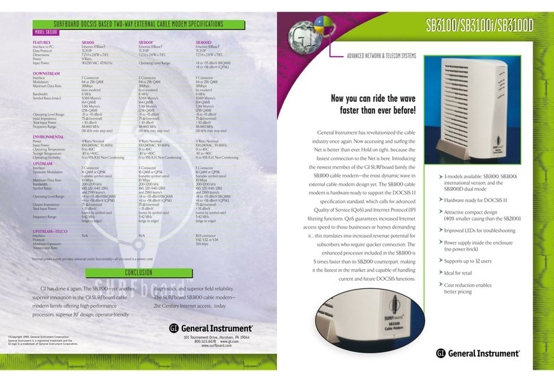
The General Instrument SURFboard®SB3100 cable modem provides the link from the home or
business computer to a high-speed DOCSIS 1.0 or 1.1 compliant data network. This network
provides a downstream data-transfer rate up to 38 Mbps in a single 6 MHz channel using 64
and 256 QAM technology. A DOCSIS RF return path provides up to 10 Mbps using QPSK and
16 QAM.
The SB3100 features:
Remote management through SNMP or internal Web pages
Automatic configuration and address assignment
Software upgrades over the network
Compatibility with PCs, Macintosh, and UNIX® operating system computers running TCP/IP
protocol
Extensive event logs for troubleshooting
)LJXUH
6%IURQWSDQHO

,QWURGXFWLRQ
6%,QVWDOODWLRQ0DQXDO
8VLQJ7KLV0DQXDO
The following sections provide information and instructions to install, configure, and operate the
SB3100.
Section 1 Introduction provides a product description, the technical helpline, and repair/return information.
Section 2 Overview describes the functions of the SB3100 and identifies the front-panel LEDs and the rear-panel
connectors.
Section 3 Installation and Operation provides instructions on how to install the SB3100.
Section 4 HTML User Interface provides information on the user interface windows.
Section 5 Troubleshooting provides troubleshooting tips.
Appendix A Specifications provides the technical specifications for the SB3100.
Appendix B Events Log Messages provides a description of the format and field codes of the diagnostic events log.
Abbreviations and
Acronyms
The Abbreviations and Acronyms list contains the full spelling of the short forms used in this manual.
'RFXPHQW&RQYHQWLRQV
Before you begin using the SB3100, familiarize yourself with the stylistic conventions used in
this manual:
Bold type Indicates text that you must type exactly as it appears or indicates a default value
SMALL CAPS Denotes silk screening on the equipment, typically representing front- and rear-panel controls and input/output
(I/O) connections, and LEDs
Italic type Denotes a displayed variable, a variable that you must type, or is used for emphasis
.(<
.(<
Key combinations indicating that you hold down the first key and then press the second key
&RXULHUIRQW
Indicates text displayed on a graphical user interface (GUI)
,I<RX1HHG+HOS
If you need assistance while working with the SB3100, call the General Instrument Technical
Response Center (TRC) at 1-888-944-HELP (1-888-944-4357). The TRC is open from 8:00 AM
to 7:00 PM Eastern Time, Monday through Friday. When the TRC is closed, emergency service
only is available on a call-back basis.
When contacting the TRC from outside the United States, call the main switchboard number,
1-215-323-1000, and ask for extension 4200.

,QWURGXFWLRQ
6%,QVWDOODWLRQ0DQXDO
&DOOLQJIRU5HSDLUV
If repair is necessary, call the General Instrument Repair Facility at 1-800-227-0450 for a
Return for Service Authorization (RSA) number before sending the unit. The RSA number must
be prominently displayed on all equipment cartons. The Repair Facility is open from 8:00 AM to
5:00 PM Central Time, Monday through Friday.
When calling from outside the United States, use the appropriate international access code and
then call 956-541-0600 to contact the Repair Facility.
When shipping equipment for repair, follow these steps:
Pack the unit and accessories securely in the original shipping carton, if possible.
Enclose a note describing the exact problem or complete the Troubleshooting checklist in
Section 5, Troubleshooting. Enclose a copy of the invoice that verifies the warranty status.
Ship the unit PREPAID to the following address:
General Instrument Corporation
Attn: RSA #___________
5964 E. 14th Street
Brownsville, TX 78521

6%,QVWDOODWLRQ0DQXDO
6HFWLRQ
2YHUYLHZ
The SB3100 cable modem delivers digital multimedia content in a two-way transmission
system. It provides access to a data network running over the cable system, which provides
access to the worldwide web.
The SB3100 is authorized by the Cable Modem Terminations System (CMTS) for use on the
network and automatically configures itself with the parameters received from the CMTS or
headend. When the SB3100 is powered on, it scans the frequency spectrum to locate the data
frequency and then automatically locks on to that channel. After finding the data channel, it
searches for a message containing the upstream parameters such as frequency, modulation,
symbol rate and forward error correction (FEC) format. The SB3100 then transmits a message
to the CMTS requesting additional information that enables network connection. Through a
series of messages, the SB3100 establishes Internet Protocol (IP) connectivity using Dynamic
Host Configuration Protocol (DHCP) and then receives a configuration file using the Trivial File
Transfer Protocol (TFTP). This configuration file contains additional parameters that are
required by the SB3100. When the configuration is complete, the SB3100 registers with the
CMTS and is authorized to use the network.
Figure 2-1 illustrates SB3100 data path:
)LJXUH
6%GDWDSDWK
10Base-T
Internet
IF RF
RF
RF
HFC plant
Upconverter
Client PC
SB3100
external
cable
modem
Diplex
filter
CMTS
Network
management
services
Customer premises
equipment
10Base-T
The SB3100 supports 64 and 256 QAM technology that are necessary for the DOCSIS data
network. This network carries IP data in standard MPEG-2 packets. The RF downstream
receives data at speeds up to 38 Mbps and RF upstream provides data transfer at rates up to
10 Mbps.
The SB3100 provides an HTML user interface that enables you to monitor both the cable
modem and the data signals. This interface can be used to diagnose the network connections.

2YHUYLHZ
6%,QVWDOODWLRQ0DQXDO
)URQW3DQHO
The five front-panel LEDs provide status and activity information as illustrated in Figure 2-2:
)LJXUH
6%IURQWSDQHO
1
3
4
5
2
Table 2-1 describes the front-panel LEDs:
7DEOH
)URQWSDQHO/('V
.H\ /(' 'HVFULSWLRQ
1Power Flashing green indicates performing startup diagnostics. Solid green indicates power on and completed
diagnostics successfully.
2Receive Flashing green indicates scanning for the downstream frequency. Solid green indicates the downstream
channel is acquired.
3Send Flashing green indicates scanning for the upstream channel. Solid green indicates the upstream channel
is acquired.
4Online Flashing green indicates requesting an IP address (DHCP), downloading the configuration file (TFTP), and
obtaining network time (TOD). Solid green indicates the SB3100 has successfully completed
DHCP/TFTP/TOD and activities noted above for Power, Receive, and Send.
5Activity Flashing amber when data is transmitted on the downstream or upstream connection. When is LED is off,
it indicates no data transfer.

2YHUYLHZ
6%,QVWDOODWLRQ0DQXDO
If an error occurs:
During the startup, the specific LEDs is off. For example, if the downstream channel is not
acquired, the RECEIVE LED goes from flashing to off. This provides immediate feedback as to
where the problem has occurred.
During normal operation, the LED corresponding with the failure is off. For example, if the
downstream channel is lost, the RECEIVE LED goes from on to off. By noting the LED status, you
can determine the source of the problem.
5HDU3DQHO
The back panel provides the connectors for all cabling, status LEDs, and the power reset button
as illustrated in Figure 2-3:
)LJXUH
5HDUSDQHOFRQQHFWLRQV
1
2
6
5
4
3
$&7
/,1.
(1(7
32:(5
&$%/(

2YHUYLHZ
6%,QVWDOODWLRQ0DQXDO
Table 2-2 describes the rear-panel connections:
7DEOH
5HDUSDQHOFRQQHFWLRQV
.H\ ,WHP 'HVFULSWLRQ
1ACTFlashing LED indicates data transfer over the Ethernet connection.
2ENET This port provides data transfer to and from the computer. This is an RJ-45 connector
3LINK When the LED is on, the Ethernet connection is available.
4This is an access port for the power-reset button.
5CABLE This port provides data transfer to and from the service provider. This is an F-type connector.
6POWER This connector provides power to the SB3100.

6%,QVWDOODWLRQ0DQXDO
6HFWLRQ
,QVWDOODWLRQDQG2SHUDWLRQ
This section provides instructions for cabling the SB3100 and checking its operation. To
complete the installation, you must:
n
Connect the cables
n
Configure the customer’s computer
n
Power up the unit
%HIRUH<RX%HJLQ
Before you begin the installation, take a few minutes to review the installation information,
gather the required items, and complete the tasks listed below to make the installation as quick
and easy as possible:
Verify that you received the following items with your SB3100 shipment:
Power cord Acceptable for use with NEMA Style 5-15R ac receptacles supplying nominal 120 V
10Base-T Ethernet cable Required to connect your computer to the cable modem
Acquire the following items that are not included with the SB3100:
75-ohm coaxial TV cable Required to connect the SB3100 to the nearest cable outlet
5-900 MHz splitter Required if a TV is attached to the cable outlet
Laptop or PC with TCP/IP
and HTML browser
Required to access the internal Web server for diagnostics
Verify that the customer’s computer has an Ethernet card installed.

,QVWDOODWLRQDQG2SHUDWLRQ
6%,QVWDOODWLRQ0DQXDO
,QVWDOOLQJD6LQJOH8VHU
To install the SB3100:
Connect the coaxial TV cable to the SB3100 connector marked CABLE and the other end to
the cable outlet or splitter. You may need a 5-900 MHz splitter if there is a TV connected to
the cable outlet. Figure 3-1 illustrates the connections:
)LJXUH
&DEOHFRQQHFWLRQV
$&7
/,1.
(1(7
&$%/(
32:(5
Ethernet to
computer
TV cable to
cable outlet
Power cord
to electrical
outlet
Connect the 10Base-T Ethernet cable to the SB3100 connector marked ENET and the other
end to the Ethernet jack on the back of the computer.
Connect the power cord to the SB3100 connector marked POWER and plug the other end to
the electrical outlet.

,QVWDOODWLRQDQG2SHUDWLRQ
6%,QVWDOODWLRQ0DQXDO
,QVWDOOLQJ0XOWLSOH8VHUV
The SB3100 can easily serve as a gateway to the Internet for up to 32 users. The users must be
on the LAN and the SB3100 must be attached to the LAN and the cable system. Figure 3-2
illustrates the basic connections:
)LJXUH
0XOWLSOHXVHUFRQQHFWLRQV
Service
provider
Crossover
Ethernet cable
Standard
Ethernet cable
Ethernet
hub
Computer
Computer
Computer
SB3100
TV cable
3RZHULQJ8SWKH)LUVW7LPH
Powering up the SB3100 may take 15 to 30 minutes the first time because it must find and lock
on the appropriate channels for downstream and upstream communications. To power up:
Verify that the computer is on and the cable modem is plugged in.
Check that the LEDs on the front panel cycle through this sequence:
The POWER LED flashes during a self-test. When the self-test is successfully complete,
the LED is solid green.
The RECEIVE LED flashes while the SB3100 scans for the downstream channel. When
the downstream channel is locked, the LED is solid green.
The SEND LED flashes while the SB3100 scans for the upstream channel. When the
upstream channel is locked, the LED is solid green.
The ONLINE LED flashes while the SB3100 is obtaining the DHCP address,
configuration, and time and date stamp. When the SB3100 has obtained the address and
configuration information, the LED is solid green
The SB3100 automatically loads configuration updates. It automatically reboots if the IP
address and the time and date stamp are not found.
If an error occurs during the startup, the specific LEDs turn off. For example, if the downstream
channel is not acquired, the RECEIVE LED goes from flashing to off. This provides immediate
feedback as to where the problem has occurred. Refer to Section 5, “Troubleshooting” for details.
The modem should remain on. It is not necessary to turn it off when not in use.

,QVWDOODWLRQDQG2SHUDWLRQ
6%,QVWDOODWLRQ0DQXDO
&RQILJXULQJWKH&RPSXWHU
The SB3100 contains all necessary software. The computer must be configured for TCP/IP and
have an IP address assigned. The basic instructions are provided using Windows™ 95 or
Windows 98.
7&3,3
To configure for TCP/IP:
On the Windows Desktop, click Start. The pop-up menu is displayed.
Select Settings and the Control Panel from the pop-up menus.
Double-click the Network icon on the Control Panel window. The Network window is
displayed as illustrated in Figure 3-3:
)LJXUH
1HWZRUNZLQGRZ
Select the Configuration tab on the Network window.
Verify that TCP/IP has been installed for the Ethernet card. If it appears in the network
components installed list, proceed to step 12.

,QVWDOODWLRQDQG2SHUDWLRQ
6%,QVWDOODWLRQ0DQXDO
Click Add. The Select Network Component Type window is displayed as illustrated in
Figure 3-4:
)LJXUH
1HWZRUN&RPSRQHQW7\SHZLQGRZ
Double-click the Protocol option. The Select Network Protocol window is displayed as
illustrated in Figure 3-5:
)LJXUH
6HOHFW1HWZRUN3URWRFROZLQGRZ
Click Microsoft in the Manufacturers section and then click TCP/IP in the Network
Protocols section.

,QVWDOODWLRQDQG2SHUDWLRQ
6%,QVWDOODWLRQ0DQXDO
Click OK. The Network window is displayed as illustrated in Figure 3-6:
)LJXUH
1HWZRUNZLQGRZZLWK7&3,3VHOHFWHG
Click TCP/IP on the Network window. If you have more than one TCP/IP entry, choose the
one associated with the Ethernet card connected to the cable modem.

,QVWDOODWLRQDQG2SHUDWLRQ
6%,QVWDOODWLRQ0DQXDO
Click Properties. The TCP/IP Properties window is displayed as illustrated in Figure 3-7:
)LJXUH
7&3,33URSHUWLHVZLQGRZ
Select the IP Address tab.
Click Obtain an IP address automatically.
Click OK to accept the TCP/IP settings.
Click OK to close the Network window.
Click OK when a prompt to restart your computer is displayed and then click OK again.

,QVWDOODWLRQDQG2SHUDWLRQ
6%,QVWDOODWLRQ0DQXDO
,3$GGUHVV
To check the computer IP address:
On the Windows Desktop, click Start. The pop-up menu is displayed.
Select Run and the Run dialog box is displayed as illustrated in Figure 3-8:
)LJXUH
5XQGLDORJER[
Type winipcfg.exe and then click OK. The IP Configuration window is displayed as
illustrated in Figure 3-9:
)LJXUH
,3&RQILJXUDWLRQZLQGRZ
Verify that the pull-down list has the correct Ethernet adapter displayed.
Other manuals for SURFboard SB3100
1
Table of contents
Other General Instrument Modem manuals

General Instrument
General Instrument SURFboard SB2100 User manual

General Instrument
General Instrument SURFboard SB3100 User manual

General Instrument
General Instrument SURFboard SB3100Di User manual

General Instrument
General Instrument SURFboard SB3100D User manual

General Instrument
General Instrument SURFboard SB3100i User manual

General Instrument
General Instrument SURFboard SB2100 User manual

General Instrument
General Instrument SURFboard SB2100 User manual