CLEANING
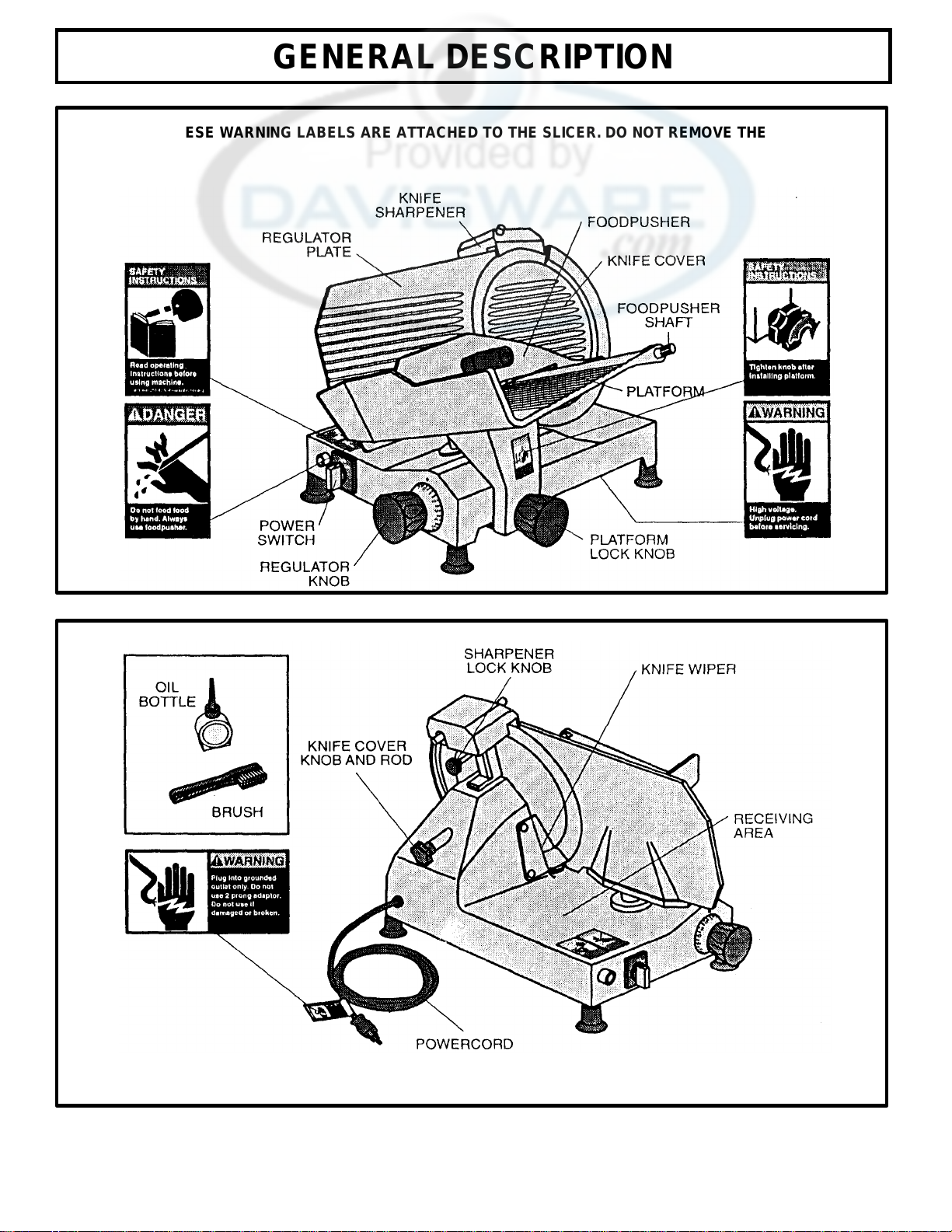
Clean and sanitize the slicer before using the first time, after each
use, and before slicing different types of food products. Follow com-
pany, local, and state health/sanitation codes.
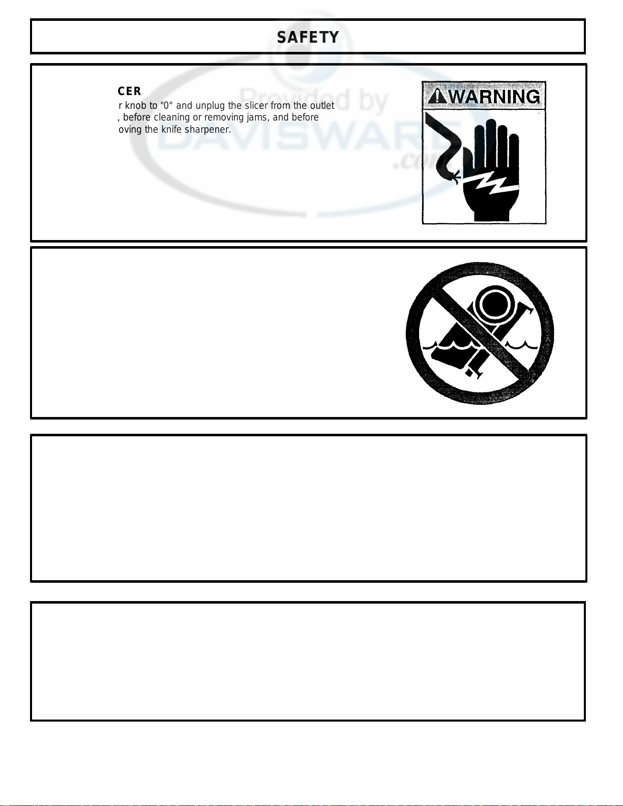
WARNING: Set the regulator knob to "0" and unplug the
slicer before cleaning or handling.
Do NOT use caustic or abrasive cleaners.
Do NOT spray cleaning materials or water toward the power switch,
the regulator knob, or the openings of the machine.
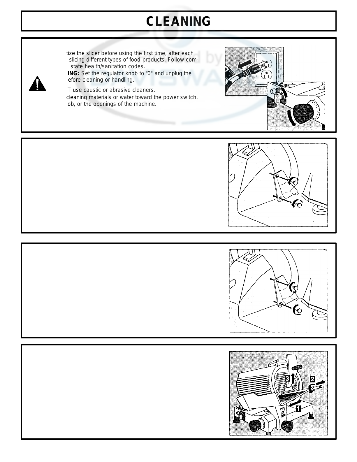
DISASSEMBLY FOR CLEANING Knife
Wiper
1. Remove the two thumbscrews by turning them counter-
clockwise.
2. Remove the knife wiper.
3. Wash the knife wiper in hot, soapy water.
4. Clean the back of the knife with hot, soapy water and a clean
cloth by wiping outward from the center.
5. Re-install the knife wiper, positioning it as close to the knife as
possible (The wiper should not touch the knife.). Replace and
tighten the thumbscrews.
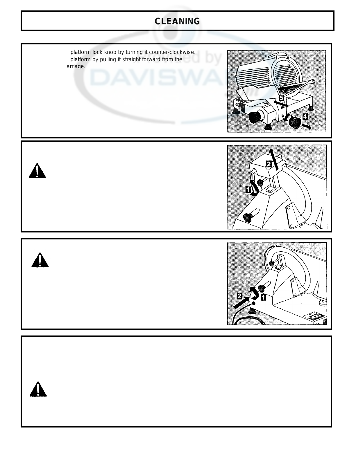
Platform Assembly
1. Pull the platform assembly to the extreme front position (toward
you).
2. Unscrew the foodpusher shaft counter-clockwise, and remove it by
pulling it away from the platform.
3. Remove the foodpusher.
7