General RL-20G User manual

1
RL-20G
ROTARY LASER LEVEL
Product Code: GRL20GSTDKT
INSTRUCTION MANUAL
MANUAL
GRADE TILT
ALARM
RPM

2
Laser Safety
• Use the tool only with the
specifically designated batteries.
• Store the tool out of reach of children and
other untrained persons. Laser tools are
dangerous in the hands of untrained users.
• Use only accessories that are
recommended for your model.
• Tool service must be performed only by
qualified repair personnel. Repairs, service
or maintenance performed by unqualified
personnel will void the warranty.
Only approved and authorised service
technicians can carry out warranty repairs.
• Do not use optical tools such as a telescope
or transit to view the laser beam. Serious
eye injury could result.
• Do not place the tool in a position which
may cause anyone to intentionally or
unintentionally stare into the laser beam.
Serious eye injury could result.
• Do not position the tool near a reflective
surface which may reflect the laser beam
toward anyone’s eyes. Serious eye injury
could result.
• Do not set up the tool at a position where
the laser beam can cross any person at
head height.
• Do not let children come in contact with
the tool.
• Turn the tool off when it is not in use.
Leaving the tool on increases the risk of
staring into the laser beam.
• Do not operate the tool around children or
allow children to operate the tool. Serious
eye injury may result.
• Position the tool securely on a level
surface. Damage to the laser or serious
injury could result if the laser falls.
• Do not remove or deface warning labels.
• Never look into the laser beam directly
and intentionally.
• Do not use optical tools to view the
laser beam.
• Do not set up the tool at a position
where the laser beam can cross any
person at head height.
• Do not let children come in contact
with the laser.
Read the following safety instructions before attempting to operate this tool.
Keep these instructions in a safe place or store in the carry pouch for future reference.
There are no user serviceable parts inside.
Disassembling the tool will void all
warranties on the product. Do not modify
the tool in any way. Modifying the tool may
result in hazardous laser radiation exposure.
CAUTION!
CLASS 2 LASER PRODUCT
WARNING! SAVE ALL WARNINGS & INSTRUCTIONS FOR FUTURE REFERENCE.
Read and understand all instructions.
!
!
WARNING!
DO NOT DISASSEMBLE THE LASER.

RL-20G KIT
3
Please ensure the following items are included with your laser level.
If anything is missing please contact your retailer.
Item Checklist
General
RL-20G
Laser glasses
(green)
Laser target
(green)
9V Alkaline
battery (detector)
2x AA Alkaline
batteries (remote)
Hard carry case
Rechargeable
battery pack
Mains power
adaptor / indoor charger
General RL-RC20G
remote control
General RL-D7H
detector & clamp
INCHES CM
1
1
2
3
4
5
6
7
2
3
MANUAL
GRADE TILT
ALARM
RPM
MANUAL
GRADE

FRONT OVERVIEW
BASE OVERVIEW
4
Using the Laser
Rechargeable
battery charging port
Protective lighthouse
Rotating laser port
Control panel
5/8” x 11 thread
for horizontal
operational on a tripod
Battery thumb screw
Rechargeable
battery charging port
5/8” x 11 tripod thread
MANUAL
GRADE TILT
ALARM
RPM
1Rotating laser port
2Protective lighthouse
3Control panel
4Rechargeable battery charging port
55/8" x 11 thread for horizontal operation on a tripod
6Battery thumb screw
7Speed control button
8Power button
9Manual grade mode button
10 Tilt alarm button
11 X/Y axis indicator (manual grade mode)
X-axis = soild LED light Y-axis = flashing LED light
12 Tilt alarm indicator
13 Power indicator

CONTROL PANEL
5
Using the Laser (continued)
Manual grade
mode button Tilt alarm button
Power button
Tilt alarm indicator
Power indicator
Speed control button
X/Y axis indicator
(manual grade mode)
POWER SUPPLY
Rechargeable battery pack
• The laser level is supplied with a rechargeable
Ni-MH battery pack that is located in the base of
the laser level.
• The rechargeable battery pack is supplied only
partially charged. Charge the rechargeable battery
pack before use. Keep the rechargeable battery
pack in the carry case when not in the laser level.
• The power indicator light will flash when the
battery is low. The laser level should be re-charged
as soon as possible.
• Battery pack capacity decreases at low
temperatures; a depleted pack may not function
when cold.
Indoor charger
• The indoor charger is for indoor use only.
• Do not store in locations where moisture can be
present or where the chargers could be exposed to
extreme temperatures.
• If a charger becomes damaged, stop using
immediately and seek a replacement.
WARNING! Only use the supplied
charger. Using an incorrect charger will
void the warranty. Do not charge alkaline
batteries.
!

FIGURE 1
6
Charging the rechargeable battery pack
• Insert the charger into one of the two charging
ports. The charging ports are located underneath
the control panel (Fig.1) and on the battery pack.
Progress will be shown by the power indicator
display on the charger as following:
Red (flashing) = Charger and battery are not
connected.
Red (constant) = Battery is charging
Green (constant) = Battery is charged
• Charging time is approximately 5 hours for a
depleted battery.
The battery pack does not need to be inserted
in the laser level whilst charging via the port
on the battery pack.
Removing and inserting the rechargeable
battery pack
• Loosen the battery thumb screw on the base of the
laser level and remove the battery pack.
• Insert the battery pack,ensuring the metal pins are
aligned. Tighten the battery thumb screw.
WARNING! Do not attempt to
disassemble the battery pack.
HORIZONTAL MEASUREMENT SETUP
Level surface set up
• Select a place as close and practical to the work
site as possible, and ensure that the location is
clear of traffic.
• Place the laser level onto a reasonably level surface
with the lighthouse facing upwards.
Using the Laser (continued)
VERTICAL MEASUREMENT SETUP
Level surface set up
• Select a place as close and practical to the work
site as possible, and ensure that the location is
clear of traffic.
• Place the laser level onto a reasonably level surface
with the control panel facing upwards.
!
MANUAL
GRADE
RPM
TILT
ALARM

7
Using the Laser (continued)
OPERATION
Powering on
• Press the power button once and the laser level will
power on and begin automatically self-levelling.
When this levelling process is complete, the penta
prism inside the lighthouse will start rotating.
• If the laser level is outside the self levelling range
the laser level will not level causing the laser beam
to flash continuously.If this occurs, reposition the
laser level onto a level surface until the laser level
can level off.
In bright outdoor conditions, visible distance
will be significantly reduced. For outdoor use,
it is recommended to use the included detector.
Powering off
• Press the power button once and the laser level
will power off.
Speed control
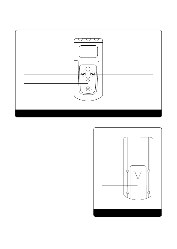
• Press the speed control button on the remote
control to cycle through various rotational speeds.
Sleep mode
• Press the sleep button on the remote control to
enter into sleep mode.
• The laser diode will stop spinning and shut off. (The
unit is not turned off in sleep mode).
• Press the sleep button on the remote control to
exit sleep mode.
After 60 minutes of inactivity during sleep
mode, the laser level will turn off automatically.
Tilt alarm
• Once the laser level has been levelled off the tilt
alarm can be enabled by pressing the tilt alarm
button.The tilt alarm indicator light will flash
continuously whilst active.
• If the laser level is disturbed while the alarm is
active the laser level will stop rotating and will
need to be powered off and on again to reset to a
level position.
Setting up a manual grade / slope
• To create a manual grade / slope, press the manual
grade mode button on the laser level control panel
or remote control.The laser level will now be in
manual mode with the X-axis active.The LED X / Y
axis indicator on the laser control panel will display
a solid light to indicate X-axis is selected.
• Press the grade adjustment arrow buttons on the
remote control.
• To change to the Y-axis, press the manual grade
mode button.The LED X / Y axis indicator on the
laser control panel will flash to indicate the Y-axis
is selected. The laser level can now be adjusted
on the Y-axis.
• Press the grade adjustment arrow buttons on the
remote control.
• To adjust the grade, press the manual grade mode
button to cycle between X andY axis
• To cancel manual grade mode, and return to
normal levelling press the power button off and on
again to reset the levelling process.
When in manual mode the laser level will
not self level and correct for vibrations and/or
disturbances.
Grade adjustments can only be made by
pressing the grade adjustment arrow buttons
on the remote control.

FRONT OVERVIEW
BACK OVERVIEW
8
Using the Remote Control
MANUAL
GRADE
Manual grade mode button
Grade adjustment
(manual mode) button
Grade adjustment
(manual mode) button
Speed control button
Battery
compartment
Sleep mode button
REMOTE CONTROL OPERATION
Power supply
• The remote is powered by two AA alkaline batteries.
Battery replacement
• Remove the battery cover door and the batteries.
• Insert the batteries according to polarity and
replace the battery cover door.
Operating the remote control
• Ensure the laser level is turned on and the laser
head is rotating.
• Grade set-up function is done via the remote
control.To set up a manual grade / slope refer
to page 7.
• For details on other remote control functions
including speed control and sleep mode, refer
to page 7.

FRONT OVERVIEW
BACK OVERVIEW
9
Using the Detector
Laser sensor
Detection mode button
Screen backlight button
Direction indicators
LCD display screen
Power button
Speaker on / off button
Battery compartment
Staff clamp mounting point
Speaker
LCD display screen

10
Using the Detector (continued)
LCD SCREEN OVERVIEW
Speaker indicator
Brightness indicator
Detection mode
Arrow indicator
Centre alignment
Arrow indicator
Battery indicator
POWER SUPPLY
• The detector is powered by one 9V alkaline battery.
Battery replacement
• Remove the battery cover door and the batteries.
• Insert the batteries according to polarity and
replace the battery cover door.
MOUNTING TO THE STAFF CLAMP
• Insert the staff clamp screw into the staff clamp
mounting point.
• Rotate the staff clamp thumb screw until the clamp
is secured in place.

11
Using the Detector (continued)
FIGURE 2
FIGURE 3
FIGURE 4
DETECTOR OPERATION
• Power the detector on by pressing the power
button.The LCD screen will turn on and the speaker
will emit a small tone to indicate the detector is
operating.
• The LCD screen will display the battery
level,detection mode and speaker function.
• To change between broad, coarse and fine mode
press the detection mode button.
• To change the speaker volume or turn the speaker
off, press the speaker button.
• To turn on the backlight,hold down the mode
button for approximately 3 seconds.
• Move the detector into the path of the laser beam.
• Hold the detector upright for horizontal beams
(Fig. 2) or rotate 90° for vertical beams (Fig.3).
• The direction arrows or level line on the LCD screen
will indicate the position of the laser beam. A
digital increment display will indicate the position
of the laser beam (Fig. 2 & 3).The detector will emit
a constant beep once the level position has been
located (Fig. 4).

12
Care & Maintenance
Calibration Check
1. This is a precision measuring tool and should
always be handled with care and transported
within the carry case provided.
2. Always turn the tool off when transporting the
laser level or moving around the job site.
3. Whenever possible, store the tool in a dry, shady
location.
4. When the tool is not in use or is being stored, it is
highly recommended to remove the batteries.
5. Calibration of the tool is recommended: every six
months, if ongoing accurate levelling is required,
or an impact has occurred.
6. The operator should check the accuracy of the tool
before precision levelling is attempted. Failure to
do so may result in inaccurate measurements.
7. Clean the tool with a dry, soft cloth after use in
dusty,damp or wet conditions before storing.
8. Smudges and fingerprints may be removed with a
damp tissue or a soft, lint-free cloth.
Mounting to a Construction Tripod
A construction tripod (flat, domed or
elevating) can be purchased from your
nearest measurement tool dealer. The
below instructions are generic only and
set-up methods may vary between models.
Refer to the documentation from the tripod
manufacturer for details.
• Extend the tripod legs to the required height and
ensure the legs are spread wide enough so that
the tripod platform is stable. Secure the legs in
place (refer to the documentation from the tripod
manufacturer for details).
• Place the laser level onto the tripod with the
lighthouse facing upwards and mount the male
5/8” thread into the base until firm. Do not over
tighten as this may cause damage to the laser
level or tripod.
• If using an elevating tripod with a measuring scale
on the centre column, the height can be adjusted
as required.
WARNING! Attaching the laser level to
a tripod without the correct thread size
may cause damage.
!
NOT INCLUDED
Before doing any precision levelling it is advised to
check the calibration of the laser level.
• Set up the laser level on a tripod at about 30m
facing a wall or staff with a detector.
• Allow the laser to level.
• Detect and note laser position on the wall or staff.
• Without moving the tripod, rotate the laser level
180°.
• Detect and note laser position on the wall or staff.
• Calculate the distance between the two readings.
• The difference should be within 6mm at 30m.
• If the laser level is out of calibration it is advised to
send it to an authorised service centre.

13
Trouble Shooting
Laser does not turn on
• Check the batteries.They may be in the wrong way or need replacing.
• Check the battery compartment for signs of damage and ensure that the
compartment is clean and that the battery terminals are not bent.
Laser does not remain on
for long periods of use
• Check the batteries.They may need replacing.
• Check the battery compartment for signs of damage and ensure that the
compartment is clean and that the battery terminals are not bent.
Laser does not level off
• The tool may be outside its self levelling range and may require an
adjustment before self-levelling can commence.
• The tool may have impact damage.
Battery pack will not
charge or is not lasting
long in use
• Check the battery pack.The battery pack may require charging or need to
be replaced due to age and / or a high number of charging cycles.
• Check the battery compartment for signs of damage and ensure that the
compartment is clean and that the battery terminals are not bent.
Battery pack will not
charge or is not lasting
long in use
• Check the batteries on the detector.They may be low and need replacing.
• Check the laser settings and ensure the laser is producing a beam.
• Check the line of sight and ensure there is no interference.
• Check that the laser level and detector are within the operating range.
ERROR CAUSE & SOLUTION

14
Warranty
1. Our warranty provides the correction of
deficiencies to the tool once verified by an
authorised service centre that the deficiencies
were caused by a manufacturing fault within
the warranty period.
2. The standard warranty period is 3 years from
the date of purchase. The warranty period can
be extended to 7 years upon registration of the
tool within 30 days of purchase.
3. The warranty does not cover:
a) Calibrations and components that are
subject to wear and tear.
b) Defects in the tool caused by
non-compliance with the operation
instructions, improper use, abnormal
environmental conditions, inappropriate
operating conditions or insufficient
maintenance.
c) Defects caused by using accessories or spare
parts other than approved parts.
d) Services or repairs carried out by
non-authorised persons.
4. Defects recognised by an authorised service
centre as being covered by the warranty shall
be corrected either by repair or replacement
of the tool.
5. The warranty claim must be lodged within the
warranty period. This requires the complete
tool with the original sales receipt containing
the purchase date and place of purchase.
Partial or disassembled tools cannot be
submitted for a warranty claim.
This tool comes with a standard 3 year warranty. Extend the warranty of your
laser level to 7 years by registering online. See website for terms and conditions.
All Spot-on measurement tools are carefully checked and tested to our precise quality assurance standards.
We offer a warranty in accordance with the following conditions:
www.spoton.com.au/warranty-information
6. Services provided under warranty do not
lengthen or renew the warranty of the tool.
“Our goods come with guarantees that cannot
be excluded under the Australian Consumer Law.
You are entitled to a replacement or refund for
a major failure and for compensation for any
other reasonably foreseeable loss or damage.
You are also entitled to have the goods repaired
or replaced if the goods fail to be of acceptable
quality and the failure does not amount to a major
failure.”
For more information please visit
www.consumerlaw.gov.au
3 YEAR STANDARD WARRANTY PERIOD
1. The warranty period for your tool is 3 years
from the date of purchase.
2. The warranty period for batteries, battery
packs and chargers is 1 year from the date of
purchase.
3. Calibrations are not covered under warranty as
they are deemed wear and tear.
4. All products have a standard warranty period,
you do not have to register your products to
obtain the standard warranty period.
5. To claim under this warranty, the date of
purchase of the tool must be documented by
an invoice/receipt.

15
7 YEAR EXTENDED WARRANTY PERIOD
1. The extended warranty is available on selected
tools only.
2. You may extend the warranty period for your
tool to 7 years from the date of purchase. This
excludes batteries, battery packs and chargers.
3. Calibrations are not covered under warranty as
they are deemed wear and tear.
4. To obtain the extended warranty, the
registration process must be completed within
30 days from the date of purchase.
To assist you with any queries or technical
questions please contact customer support.
1300 658 338
Visit www.spoton.com.au for more information.
Customer Support
Product code GRL20GSTDKT
Warranty 7 Years (with online registration)
Accuracy ±1.5mm at 10m
Operating range 300m (diameter)
Levelling range ±9% / ±5°
Laser class 3 Green
Battery life 20 hours +
IP rating 65
Weight (kg) 2.38
Dimensions (mm) 210 x 157 x 200
Specications
SPECIFICATIONS
5. Failure to register your product online and/or
submission of a valid invoice/receipt will void
the warranty extension.
6. Please ensure ALL information submitted/
uploaded is correct.
7. Extended warranty is ONLY available via online
registration, offline (mailing in of warranty
registration) will not be accepted.
Warranty (continued)

Spot-on Laser & Tool Company
Spot-on Laser & Tool Company reserves the right to make changes to specications and product descriptions at any time.
© Spot-on Laser & Tool Company. 2021. Printed in China.
This manual suits for next models
1
Table of contents
Other General Laser Level manuals

General
General X3G User manual

General
General X5 User manual

General
General Titanium Series User manual

General
General ML-3DR User manual

General
General GML3DGSTDKT User manual

General
General ML-3DG User manual

General
General XL1 User manual

General
General 3DG User manual

General
General RL-20R User manual

General
General Titanium Series User manual