General J-1400 User manual

OPERATOR’S MANUAL
General Wire Spring Co USA 1-412-771-6300 or 1-800-245-6200
Any alteration to equipment without prior written approval of the manufacturer will cancel any warranty or
liability extended to the purchaser by manufacturer. For approval or assistance contact General Wire Spring Co.
8.914-322.0 / 97-6115
J-1400 and J-1600
JET SET
TM

CONTENTS
2
Model Number ______________________________
Serial Number ______________________________
Date of Purchase ____________________________
The model and serial numbers will be found on a decal attached
to the machine.You should record both serial number and date of
purchase and keep in a safe place for future reference.
General's Jet SetTM Models J-1400 & J-1600 • Form #8.914-322.0 / 97-6115 • REVISED 4/08
Introduction.................................................................................................................................... 3
Machine Safety ...........................................................................................................................3-4
Assembly ....................................................................................................................................... 4
Pre-Operation Check ..................................................................................................................... 4
Set-up Procedures..................................................................................................................... 4, 7
J-1400 Component Identification & Use ........................................................................................ 5
J-1600 Component Identification & Use ........................................................................................ 6
Operating Instructions.................................................................................................................8-9
Maintenance .................................................................................................................................. 9
Exploded View, J-1400 ................................................................................................................ 10
Exploded View, J-1400 Parts List ............................................................................................... 11
Exploded View, J-1600 ................................................................................................................ 12
Exploded View, J-1600 Parts List ................................................................................................ 13
HR-200W Handy-Reel with Foot Pedal ....................................................................................... 14
Hose and Spray Gun Assembly (Optional) .................................................................................. 15
Pump Exploded View................................................................................................................... 16
Pump Parts List & Specifications................................................................................................. 17
Troubleshooting ......................................................................................................................18-19
Warranty ...................................................................................................................................... 21

GENERAL'S JET SET TM OPERATOR’S MANUAL 3
GENERAL'S JET SETTM J-1400 & J-1600 • 8.914-322.0 / 97-6115 • REVISED 4/08
INTRODUCTION
Thank you for purchasing a General's Jet Set™.
This manual covers the operation and maintenance of
models J-1400 and J-1600. All information in this manual
is based on the latest product information available at
the time of printing.
General Wire Spring Co. reserves the right to make
changes at any time without incurring any obligation.
Owner/User Responsibility:
The owner and/or user must have an understanding of
the manufacturer’s operating instructions and warnings
before using this General's Jet Set.Warning information
should be emphasized and understood. If the operator
is not fluent in English, the manufacturer’s instructions
and warnings shall be read to and discussed with the
operator in the operator’s native language by the pur-
chaser/owner, making sure that the operator compre-
hends its contents.
Owner and/or user must study and maintain for future
reference the manufacturers’ instructions.
This manual should be considered a permanent
part of the machine and should remain with it if
machine is resold.
When ordering parts, please specify model and
serial number.
MACHINE SAFETY
CAUTION:To reduce the risk of in-
jury, read operating instructions
carefully before using.
1. Read the owner's manual
thoroughly. Failure to follow
instructions could cause mal-
function of the unit and result
in death, serious bodily injury
and/or property damage.
2. All installations must comply with local codes. Con-
tact your electrician, plumber, utility company or the
selling distributor for specific details.To comply with
the National Electrical code (NFPA 70) and provide
additional protection from risk of electric shock, the
machines are equipped with a UL approved ground
fault circuit interrupter (GFCI) power cord.
WARNING: Flammable liquids
can create fumes which can ig-
nite causing property damage or
severe injury.
WARNING: Risk of explosion --
do not spray flammable liquids.
3. Risk of explosion - do not spray flammable liquids
or operate in an area where flammable or explosive
materials are used or stored.
WARNING: Keep water spray
away from electric wiring or fatal
electric shock may result.
4. To protect the operator from
electrical shock. The machine
is equipped with a Ground Fault
Circuit Interuptor (GFCI). The
use of an additional extension
cord by the operator should not
be used as it will not provide protection to the op-
erator of electrical shock. The machine must be
electrically grounded. It is the responsibility of the
owner to connect this machine to a UL grounded
receptacle of proper voltage and amperage ratings.
Do not spray water on or near electrical components.
Do not touch machine with wet hands or while
standing in water. Always disconnect power before
servicing.
5. Grip cleaning wand or hose securely with both hands
before starting the cleaner. Failure to do this could
result in injury from a whipping wand or hose.
WARNING: High pressure stream
of fluid that this equipment can
produce can pierce skin and its
underlying tissues, leading to
serious injury and possible
amputation.
6. High pressure developed by
these machines will cause
personal injury or equipment
damage. Use caution when operating. Do not direct
discharge stream at people, or severe injury or death
will result.
7. Never make adjustments on machine while in op-
eration.
WARNING: High pressure spray
can cause paint chips or other
particles to become airborne and
fly at high speeds.
8. Eye safety devices, foot pro-
tection and protective clothing
must be worn when using this
equipment.
9. Do not operate with the valve in the off position for
extensive periods of time as this may cause damage
to the pump.
10. The best insurance against an accident is precaution
and knowledge of the machine.
KEEP WATER SPRAY
AWAY FROM ELEC-
TRICAL WIRING.
WARNING
READ OPERATOR’S
MANUAL
THOROUGHLY
PRIOR TO USE.
CAUTION HIGH PRESSURE
SPRAY CAN PIERCE
SKIN AND TISSUES.
CAUTION
WARNING
RISK OF EXPLOSION:
DO NOT USE WITH
FLAMMABLE LIQUIDS.
WARNING
USE PROTECTIVE
CLOTHING WHEN
OPERATING.

4GENERAL'S JET SET TM
OPERATOR’S MANUAL
GENERAL'S JET SETTM J-1400 & J-1600 • 8.914-322.0 / 97-6115 • REVISED 4/08
11.
General Wire Spring Co. will not be liable for any chang-
es made to our standard machines or any components
not purchased from General Wire Spring Co.
12. Be certain all fittings are secured before using pres-
sure washer.
13. Never run pump dry.
14.
Inlet water supply must be cold and clean fresh water.
15. Do not allow children to operate the General's Jet
Set™at any time.
16. Protect from freezing.
17. When the machine is working, do not cover or place
in a closed space where ventilation is insufficient.
ASSEMBLY
Upon arrival, inspect the shipping crate for damages.
Uncrate and examine all parts. Note any damage to ma-
chine or components for claims against freight carrier.
Jets have antifreeze in the pump to protect it from freez-
ing conditions during shipment and storage. If machine
will be stored and operated in a cold climate, follow
Freeze Protection instructions on page 9.
PRE-OPERATION CHECK
Pump oil (SAE 30W non-detergent oil)
Cold clean fresh water supply (6 gpm • 5/8"
(15.875 mm) • 20 psi)
Hose, nozzle
Water filter (intact, non-restrictive)
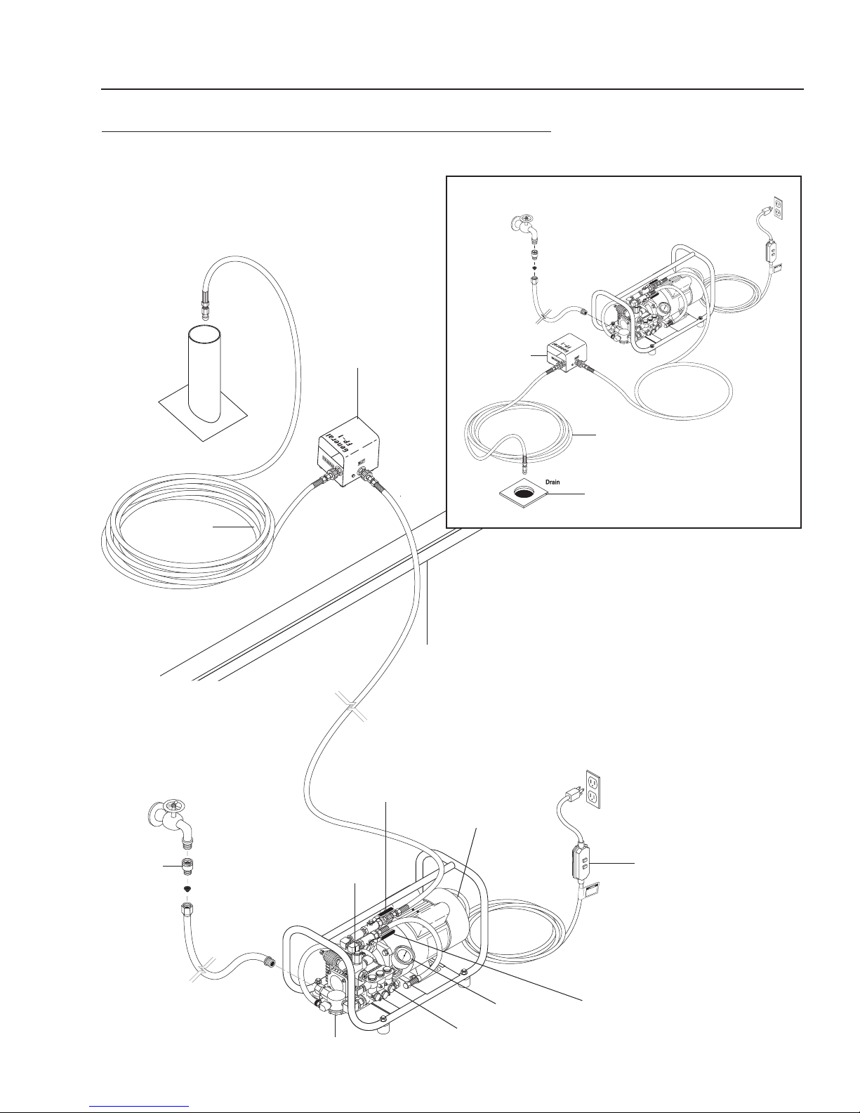
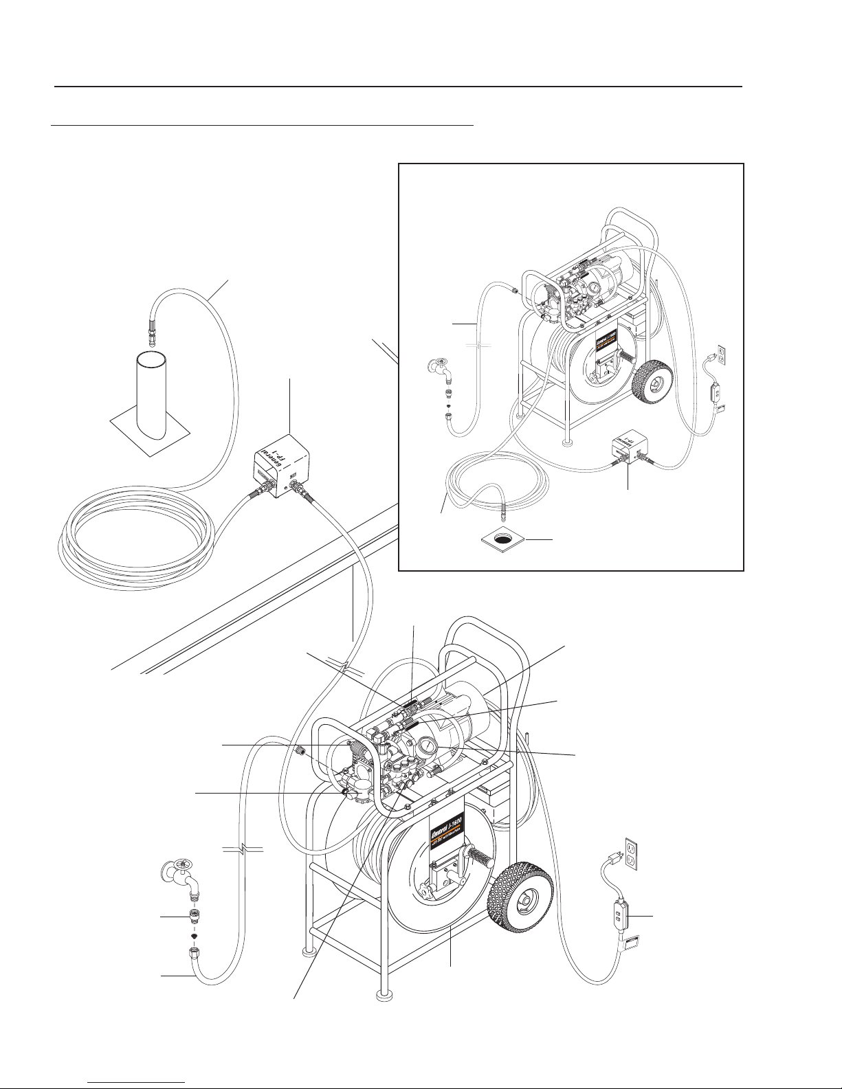
SET-UP PROCEDURES
These machines are meant to be used at or near the
working area and under operator supervision. If machine
must be located out of sight of the operator, special con-
trols may be required for proper machine operation and
operator safety.
Locate equipment on a solid level area with slopes for
drainage. Avoid areas where water can be sprayed at
machine. Before using the jet, make sure there are no
impurities in the incoming water supply. Turn the water
source on for at least 15 seconds, to remove any pos-
sible debris in the water before connecting hose to water
inlet swivel.
The inlet screen located inside the filter should be
cleaned before each use. To clean the inlet screen,
unscrew cap beneath the filter, remove the screen and
rinse thoroughly with water. Then replace screen.
Connect one end of a garden hose (not included) to
the water faucet — water supply not to exceed 100 psi
(6.9 Bar) and the other end to the water inlet of the jet
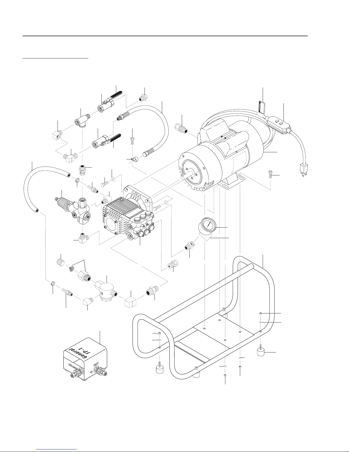
machine. (See component identification drawings on next
pages.) Use heavy duty 3/4" hose of no more than 50 ft.
(15m) in length. If run without an adequate water sup-
ply, the pump will cavitate. Cavitation causes the pump
to vibrate, causing damage to the pump. Note: Lack of
water supply can lead to seal damage, causing a loss of
pressure and will void the warranty to the pump.
Maximum temperature from water source should not
exceed 140°F (60°C). Using water hotter than 140°F
(60°C) can cause damage to pump and void the war-
ranty. If jet is being used to clear ice blockages, see
instructions on page 8.
Remove oil plug on top of pump and replace with dipstick
supplied.
Hose Selection Guide
Select the proper hose diameter for the line to be
cleaned. When using new hose, run water through it to
clean it out before attaching the nozzle.
When selecting hose size, consider that pressure is lost
as the water travels down the length of the hose. As the
length increases, the pressure decreases. In addition,
the smaller the diameter of the hose, the greater the
loss of pressure per foot will be. As an example, at 2
GPM (.13L/sec) a 1/4" (6.350 mm) hose will lose 180
lbs. (12.4 bar) of pressure over 100 ft. (30.5m) of hose,
yet a 3/8" (9.925mm) hose will only lose 25 lbs. (1.7 bar)
of pressure over the same length and at the same flow
rate. At 4 GPM, a 3/8" hose will lose 90 lbs. (6.2 bar) of
pressure over a 100 ft.(30.5m) length.The gauge reflects
pressure from the pump only, not pressure at the end
of the hose. It is important to select the largest possible
hose size in order to have as much pressure as possible
at the end of the hose.
Hoses of the same diameter may be coupled together
using the CC-1 coupling, but it is not recommended for
use in lines smaller than 8" (203mm) in diameter. The
long length of the hose connectors and coupling together
can get caught in bends in the line.
Coupling two different size hoses can be done through
the spray wand trigger or foot pedal.
It is not advisable to have two different hose sizes coupled
in a drain line. There is a tremendous loss of pressure
when combined, aside from the difficulty of getting around
bends.
The 3/8" (9.925 mm) and 1/4" (6.350 mm) hoses may
be attached to the fitting in the core of the hose reel
Hose Size (ID)* Pipe Size Typical Applications
3/8" or 5/16"
(9.925mm to
7.938mm)
4" to 8"
(102mm to 203mm)
Floor drains, septic lines, long
runs
1/4"
(6.350mm)
2" to 4"
(51mm to 102mm)
Kitchen sinks, laundry drains,
clean outs
1/8"
(3.175mm)
1-1/2" to 2"
(38mm to 51mm)
Small lines, bathroom sinks,
tight bends
*Inside Diameter

GENERAL'S JET SET TM OPERATOR’S MANUAL 5
GENERAL'S JET SETTM J-1400 & J-1600 • 8.914-322.0 / 97-6115 • REVISED 4/08
J-1400 COMPONENT IDENTIFICATION AND USE
DRAIN CLEANING
Roof
Vent
Foot Pedal
(Optional)
Pressure Gauge
Unloader
Valve GFCI
Pump
Backflow
Preventer
Motor
Through Roof Vent
Through Floor Drain
Drain
Inline Strainer
Foot Pedal
(Optional)
Roof
Pulse Control Valve
Pressure Valve
Jetter
Hose
Jetter
Hose

6GENERAL'S JET SET TM
OPERATOR’S MANUAL
GENERAL'S JET SETTM J-1400 & J-1600 • 8.914-322.0 / 97-6115 • REVISED 4/08
1600 COMPONENT IDENTIFICATION AND USE
DRAIN CLEANING
Through Roof Vent
Roof
Vent
Foot Pedal
(optional)
Roof
Hose
Reel
Inline
Strainer
Pressure
Gauge
Unloader
Valve
Pump
Backflow
Preventer
Motor
GFCI
Jetter
Control
Valve
Pulse Control
Valve
Floor
Drain
Through Floor Drain
Foot Pedal
(Optional)
Jetter
Hose
Water
Supply
Hose
Jetter
Hose
Detergent
Injector
Water
Supply
Hose

GENERAL'S JET SET TM OPERATOR’S MANUAL 7
GENERAL'S JET SETTM J-1400 & J-1600 • 8.914-322.0 / 97-6115 • REVISED 4/08
Powerful penetrating
nozzle cuts through
grease and ice.
Wide spray flushing
nozzle cleans inside of
pipe thoroughly.
Optional:
Downhead nozzle takes
hose down Tee's and
around difficult corners.
Optional:
Rotary nozzle scours
walls of pipe crystal clear
using the swivel at one end of the hose. The 3/8" hose
may also be attached directly to the accessory outlet
by using a twist connect. The 1/4" and 1/8" (3.175mm)
hoses may be connected directly to the accessory out-
let if an adapter fitting (AD-1 or AD-2) is used between
the hose and quick connect. Adapters may be ordered
separately.
Often, the 1/8" hose is used in conjunction with the spray
wand trigger to give the operator finger tip control. Re-
move the spray wand from the trigger and attach the
1/8" hose using the AD-3 adapter.
A foot pedal FP-1 valve is available that can be used as
a safety shut-off valve for all hose sizes. See foot pedal
section for installation and operating instructions.
Nozzles
A number of types of nozzles are available for drain
cleaning. Each has a different spray pattern. Some
nozzles may have a hole in the front to cut though the
stoppage.All will have holes in the back to drive the hose
down the line and clean the walls of the pipe. A tight spray
pattern (15°) has more driving power for long runs, a wide
spray pattern (40°) does a better job of cutting the grease
off the walls of the pipe. A combination of nozzles may
be required to clear a line. Always turn off the machine
and shut off valve before changing nozzles.
Make sure the nozzle you are using matches the pump
size. A 3000 psi (207 bar) pump requires a different
nozzle orifice than a 1500 psi (104 bar) pump. Mismatch-
ing nozzles with pump size will either cause too little
pressure which may not clear the drain, or too much
pressure which may damage the machine.
Check nozzles before and after each use for clogged
holes which can cause pressure to increase to danger-
ously high levels and damage the pump. A clogged hole
can be cleared by simply using the NCT Nozzle Cleaning
Tool.
Use the nozzle selection guide to determine what nozzle
you will need for various applications. Example: If a
nozzle is stamped #22, it is a JN-22, 15° rearjets, 2 GPM
(.13L/Sec) @ 1500 PSI (104 Bar) with a forward cutting
jet. Spring leader nozzles and down head nozzles are
special nozzles to help aid hose travel through the pipe
when there are alot of curves and bends.
Rotary Nozzles
Rotary nozzles are useful as a finishing tool. After the
line has been cleared, you may switch to the rotary
nozzle to more thoroughly clean the walls of the pipe.
Use these nozzles only in a predominantly straight run
since they are longer than regular nozzles and may get
caught in tight bends.
Pre-Operation Checklist
Be sure you understand all safety precautions and
___ have been trained to use the machine.
Wear goggles or a face shield to protect your eyes
___ from spray or from any product of the spray.
Wear gloves, rubber boots and other protective
___ clothing as required.
Be sure you understand all safety precautions for
___ the detergent use.
Spring leader nozzle gets
hose around tight bends
and P-traps
NOZZLE SELECTION GUIDE
1/8" 1/4" 3/8"
15oNo Forward Jet 31 41 51
15ow/Forward Jet 32 42 52
30oNo Forward Jet 33 - -
40oNo Forward Jet - 44 54
Spring Leader (JNSL) 4 5 6
Rotary Nozzle - 4 -
* Rotary Nozzles can be adapted to 1/8" and 3/8" hose using AD-3 or AD-4 adapters

8GENERAL'S JET SET TM
OPERATOR’S MANUAL
GENERAL'S JET SETTM J-1400 & J-1600 • 8.914-322.0 / 97-6115 • REVISED 4/08
Check the labels of any substance you will spray. If
the label recommends any antidote or treatment,
___ be ready to use it.
___ Check that all lines and hoses are clear.
Check that the machine is connected to an adequate
___ water supply and that the water supply is on.
Check that traffic has not made the hose weak,
worn or damaged. Check the hose for pinching or
___ kinking. Replace any damaged hose.
___ Tighten all fluid connections securely.
OPERATING INSTRUCTIONS
Check all hoses for wear and damage. Tighten all
connections securely.
Check oil level of pump.
To begin, turn the water faucet on fully and purge air
from system.
Insert end of the jet hose 2 to 3 feet into the drain
line. Then open Jetter control valve.
Warning: Never point the end of the jet hose at a
person while operating.
Start-Up
1. Make sure that the Jetter control valve is turned on
and water is flowing through the nozzle.
2. Plug in GFCI power cord to proper receptacle and
voltage. CAUTION: Do not use additional extension
cord with machine to avoid electrical shock to the
operator.
3. Hold Jetter hose firmly to prevent it from whipping
around.
4. Turn motor switch on.
Vibra-Pulse
Pulsation makes the hose vibrate, helping the jet go
longer distances and around tight bends easier.
The pulse control valve is located on the front of the
pump. Simply turn the valve on to engage the pulse.
The pulse causes a pressure drop when it's engaged.
The pulse is most effective in a 1/8" hose. You'll note
less vibration with a 1/4" hose and almost none with a
3/8" hose. However the pulse is still effective, causing
the water to burst from the nozzle hundreds of times
per second.
If you are still having difficulty getting a hose around a
tight bend, switch to a smaller diameter hose.
Turn the pulse off before turning machine off.
Shut Down Instructions
After drain cleaning or spray washing is completed, run
clear water through the system. Always leave Jetter con-
trol valve in open position when turning off motor. Turn
off water supply and drain as much water from pump as
possible. Remove water supply hose from inlet. If you
are in a cold climate, see Freeze Protection.
Handy-Reel (Optional) HR-200
Position the reel at the drain site. Connect the jet ma-
chine to the inlet on the reel. Select and attach a nozzle
to the hose on the reel. Put the hose 2 to 3 feet into the
drain. Open the ball valve on the reel. Follow the start
up procedures.
Foot Pedal (Optional) FP-1
The foot pedal is used with any jet manufactured by
General (see page 5 or 6). It interrupts the flow of water
between the pump and the nozzle while leaving both
hands free to guide the hose. The pump will continue to
run in by-pass mode. Do not leave pump in by-pass for
more than a few minutes or the pump can be damaged.
(See Regulating Pressure Unloader on Page 9).
The foot pedal may be hooked up either at the machine
or remotely at the drain site.To use the foot pedal at the
machine, remove the hose going to the swivel on the
hose reel and attach it to the inlet side of the foot pedal.
Then, connect the accessory hose (6AHW) between the
outlet of the pedal and the swivel on the hose reel. Some
jet models may need the added length of the accessory
hose on the inlet side of the pedal.
For remote hookup, pull the hose from the hose reel to
the drain site. Attach the hose to the inlet of the pedal.
The pedal is designed for 3/8" hose fittings. If using a
1/4" hose, use the AD-1 as well.Then attach the smaller
hose (1/8" or 1/4") to the outlet side of the pedal. Use
the smaller hose to clear the drain line.
Spray Wand (Optional) SWA-1500
Follow the same procedures listed previously for safety,
set-up, operation and maintenance.To operate the spray
wand, connect the high pressure hose and trigger to the
machine.Turn on the water supply, then squeeze the trig-
ger to purge air from the system. Continue to squeeze
trigger as you start the machine.
Use caution when pressure washing.Wear goggles and
rubber gloves and boots. Do not point spray at anyone
including yourself. Do not put your hand in front of water
spray. It can penetrate the skin and cause a need for
amputation. Direct spray at close range can be powerful
enough to cause damage.
NOTE: Typical industry standard stipulates you hold the
high pressure spray nozzle approximately 6-8" from the

GENERAL'S JET SET TM OPERATOR’S MANUAL 9
GENERAL'S JET SETTM J-1400 & J-1600 • 8.914-322.0 / 97-6115 • REVISED 4/08
surface to be cleaned. When cleaning with a detergent,
apply from bottom up with an even left to right movement.
Rinse from top down with a similar motion.This will help
reduce potential streaking.
Detergent Injector (Optional) CMA-1
Refer to Component Indentification for placement of
injector. The detergent injector is an option with the J-
1400 and J-1600.
To use the detergent injector, attach one end of siphon
hose to the injector and put the filter end in the detergent
solution. Be sure the end of the hose is at the bottom of
the container or bucket. Some models have adjustable
valves to control the amount of detergent drawn through
the hose. Turn the nozzle on the end of the wand coun-
terclockwise.
Remember: Do not use corrosive material. See warn-
ing previously listed.
Adjusting Pressure Unloader Valve
The machine is equipped with an adjustable pressure
unloader to prevent pressure overload in the event that
the nozzle is plugged or the Jetter control valve or trig-
ger gun is shut off. When the machine is in the by-pass
mode, the pump will continue to run. However running in
by-pass mode for extended periods will cause damage
to the pump; no more than 5 minutes with the J-1400
and J-1600 pump. Excessive temperatures will damage
the pump and void the warranty.
The machine also comes with thermal overload pro-
tection. When water temperature in pump increases to
140°F (60°C), the thermal relief valve will release hot
water and allow cool water to enter pump from fresh
water supply.
To adjust pressure unloader turn the knob clockwise to
increase pressure and counterclockwise to decrease
pressure. Caution: Do not exceed operating pressure.
Ice Blockages
High pressure water can be used to clear an ice blockage.
A 3000 psi (207 bar) gas Jetter can clear a 4" (102mm)
line at an approximate rate of one foot per minute. The
smaller electric jet will take twice as long. Ambient air
temperature will effect these times.Use a 15° nozzle with
a forward jet. DO NOT allow the incoming water supply
to exceed 140°F (60°C) or it could cause damage to the
pump. Remember to follow the cold weather precautions
found in the freeze protection section.
Freeze Protection
To protect your machine from severe damage caused
by water freezing inside the components, it is important
to winterize it whenever it is subjected to freezing tem-
peratures.
The best way to protect the system is to keep it out of
the cold. Barring that, the next best way is to flush the
system with anti-freeze. To do so, simply attach a short
garden hose (not to exceed four feet) to inlet on the
pump and put other end into the anti-freeze container.
Be sure to remove the nozzle from the hose. Turn the
machine on to draw anti-freeze into the system. When
anti-freeze flows out of the end of the hose, turn the
machine off. With optional spray wand and trigger gun
follow above procedure. Cycle trigger on/off so that the
anti-freeze will flow into unloader and detergent injector
section of machine.
When preparing to operate equipment the next time,
remove the anti-freeze.To do so, reconnect water source,
turn pump on and direct flow of anti-freeze back into con-
tainer. Be careful not to dilute anti-freeze with incoming
water supply. Anti-freeze, if kept relatively undiluted can
be used again and again.
Hoses can also be protected from freezing by using com-
pressed air to clear them of residual water. Remember
to remove nozzle from jet hose and hold trigger of spray
wand in open position.
MAINTENANCE
Regular inspection is the key to preventing breakdowns
and prolonging the life of the equipment. Follow this
simple procedure religiously.
DAILY
Check that the water supply is adequate.
Check that the nozzle on the spray wand is not clogged
or worn out.
Check that the PUMP OIL LEVEL is within operating
range on dipstick or sight glass.
Check the INLET FILTER.
Check GFCI function.
WEEKLY
Check PRESSURE HOSE for wear and damage. Dam-
aged hose can be repaired at a local service dealer or
by your equipment dealer.
Maintenance Schedule
Use the following maintenance schedule at the stated
intervals or when your routine turns up a problem.
Pump Crankcase Oil Change: Service after the 1st
month or after 50 Hours.Then service every year or 500
hours. Use SAE 30W Non-Detergent Pump Oil to full
mark on dipstick or to center of sight glass.

10 GENERAL'S JET SET TM
OPERATOR’S MANUAL
GENERAL'S JET SETTM J-1400 & J-1600 • 8.914-322.0 / 97-6115 • REVISED 4/08
EXPLODED VIEW
J-1400
7
7
19
15
16
27
23
21
22
4
6
10
15
5
25
11
9
24
13
29
12
30
Foot Pedal
Assembly
(Optional)
26
3
14
1
2
31
8
17
28
18
20
32
33
34
35
35
30
39
40
38
21
37
30
35
41
30
35

GENERAL'S JET SET TM OPERATOR’S MANUAL 11
GENERAL'S JET SETTM J-1400 & J-1600 • 8.914-322.0 / 97-6115 • REVISED 4/08
EXPLODED VIEW PARTS LIST
J-1400
ITEM PART NO. DESCRIPTION QTY
1 6-010621 GFCI, 120V 15A W/36'
12-3 Cord 1
2 5-1004M Motor, 1.5 HP 1 PH 1725 RPM,
Magnetek TEFC 1
3 4-05001 Gauge, Pressure Panel Mount,
0-2000 PSI 1
4 5-2248 Pump, AR XTA2G15EBA-F8,
Elect 1725 RPM 1
5 2-1908 Strainer, 1/2" Inline 1
6 5-3210 Unloader, AL605, 7.8 GPM
@1500 PSI 1
7 2-30026 Valve, 3/8" Ball, Brass,
General Wire 2
8 2-0045 Tee, 3/8" Street 1
9 2-30082 Pump Protector, 1/2" 140° 1
10 4-02110000 Hose, 1/2" Push-On 13"
11 2-10942 Swivel, 1/2" MP x 3/4" GHF
w/Strainer 1
2-30062 Valve, Anti-Siphon 1
12 2-1020 Elbow, 1/2" Female, Brass 1
13 2-1007 Nipple, 1/2" Hex 1
14 2-00272 Elbow, 3/8" MNPT x 1/4" FNPT,
Steel 1
15 2-00270 Elbow, 3/8", Male Pipe 2
16 2-0006 Nipple, 3/8" Hex Steel 1
17 2-0031 Elbow, 3/8" Street 1
18 4-02157725 Hose, Pulsation, 24" 1
19 2-2115 Plug, QDISC 3/8" M x 22 mm 1
ITEM PART NO. DESCRIPTION QTY
20 2-9016 Clip, Round, 0.56 I.D. 1
21 2-9002 Clamp, Screw, #6 2
22 2-1023 Elbow, 3/8" Street 1
23 2-008801 Hose Barb, 1/2" Barb x 3/8"
MNPT, Steel 1
24 2-008802 Hose Barb, 1/2" Barb x 1/4"
MNPT, Steel 1
25 2-1022 Elbow, 1/4" Street 1
26 2-01015 Bumper, Rubber 1" w/Bolt,
5/16" x 1-1/4" 4
27 90-1017 Bolt, 3/8" x 1", NC HH 4
28 90-4009 Washer, 3/8", Lock, Split Ring 4
29 90-19713 Screw, 5/16" x 3/4" Whiz Loc 3
30 90-2001 Nut, 5/16" Flange, Whiz Loc 8
31 95-07103120 Frame, Welded Assy, J-1400 1
32 26-FP-1 Foot Pedal 1
33 2-01207 Cap, Orange, On/Off 1
34 2-01208 Cap, Orange, Vibra-Pulse,
On/Off 1
35 90-4001 Washer, 5/16" Flat 8
36 96-6115 Manual, General Jet Set,
J-1400/J1600 1
37 2-01442 Plug, Garden Hose Adapter 1
38 10-08018 Label, Warning, Service Cord 1
39 90-19716 Screw, 5/16" x 1", Whiz Loc 1
40 6-05152 Strain Relief, Small 1
41 11-3104 Tag, Water Temp to Pump 1
Not Shown

12 GENERAL'S JET SET TM
OPERATOR’S MANUAL
GENERAL'S JET SETTM J-1400 & J-1600 • 8.914-322.0 / 97-6115 • REVISED 4/08
EXPLODED VIEW
J-1600
7
8
17
15
7
19
18
17
36
35
20
28
27
16
23
22
1
2
29
10
6
15
21
5
24
25
11
12
13
29
32
40
33
Foot Pedal
Assembly
(Optional) 41
42
34
30
39
38
9
14
3
431
26
45
44
43
50
51
46
48
47
30
49
45
30
37
56 55
45
59 58
57
60
21
53
54

GENERAL'S JET SET TM OPERATOR’S MANUAL 13
GENERAL'S JET SETTM J-1400 & J-1600 • 8.914-322.0 / 97-6115 • REVISED 4/08
EXPLODED VIEW PARTS LIST
J-1600
ITEM PART NO. DESCRIPTION QTY
1 6-010621 GFCI, 120V 15A W/36'
12-3 Cord1
2 5-1004M Motor, 1.5 HP 1 PH 1725 RPM,
Magnetek TEFC 1
3 4-05001 Gauge, Pressure Panel Mount,
0-2000 PSI 1
4 5-2248 Pump, AR XTA2G15EBA-F8,
Electric 1725 RPM 1
5 2-1908 Strainer, General 1
6 5-3210 Unloader, AL605, 7.8 GPM
@1500 PSI 1
7 2-30026 Valve, 3/8" Ball, Brass,
General Wire 2
8 2-0045 Tee, 3/8" Street 1
9 2-30082 Pump Protector, 1/2" 140° 1
10 4-02110000 Hose, 1/2" Push-On 13"
11 2-10942 Swivel, 1/2" MP x 3/4" GHF
w/Strainer 1
2-30062 Valve, Anti-Siphon 1
12 2-1020 Elbow, 1/2" Female, Brass 1
13 2-1007 Nipple, 1/2" Hex 1
14 2-00272 Elbow, 3/8 MNPT x 1/4 FNPT,
Steel 1
15 2-00270 Elbow, 3/8", Male Pipe 2
16 2-0006 Nipple, 3/8" Hex Steel 1
17 2-0031 Elbow, 3/8" Street 2
18 4-02157725 Hose, Pulsation 2 ft.
19 2-2115 Plug, Q-Disc, 3/8" x 22mm 1
20 2-9016 Clip, Round, 0.56 I.D. 1
21 2-9002 Clamp. Screw, #6 2
22 2-1023 Elbow, 3/8" Street 1
23 2-008801 Hose Barb, 1/2" Barb x 3/8"
MNPT, Steel 1
24 2-008802 Hose Barb, 1/2" Barb x 1/4"
MNPT, Steel 1
25 2-1022 Elbow, 1/4" Street 1
26 2-01015 Bumper, Rubber 1" w/Bolt,
5/16" x 1-1/4" 4
27 90-1017 Bolt, 3/8" x 1-1/4", NC HH 4
ITEM PART NO. DESCRIPTION QTY
28 90-4009 Washer, 3/8", Lock, Split Ring 4
29 90-19713 Screw, 5/16" x 3/4" Whiz Loc 7
30 90-2001 Nut, 5/16", ESNA 12
31 95-07103120 Frame, Welded Assy, J-1400 1
32 4-027510281 Swivel, 3/8" x 3/8" 1
33 4-02751016 Hose Reel, 13", General Wire 1
34 4-0303 Wheel & Tire Assy, 4" Tubeless,
Silver Rim, 5/8" HUB 2
35 4-02037828 Hose, 3/8" x 28", 1 Wire, 3/8"
MPT x 3" MPTS 1
36 2-2113 Coupler, 3/8" Female
Screw-Type 7640 1
37 95-07103160 Assy, Frame, J-1600 1
38 95-07103161 Axle, 21.75", J-1600 1
39 95-07103208 Assy, Tool Box, Orange,
General Wire 1
40 11-201600 Label, J-1600 w/Vibra Pulse 1
41 2-01019 Foot, Rubber (Crutch) 2
42 90-200420 Cap, 5/8" Axle 2
43 26-FP-1 Foot Pedal 1
44 90-50041 Latch, Finger 1
45 90-4001 Washer, 5/16", Flat 12
46 2-01101 Grip, 1", Handle (Waffle) 1
47 90-10001 Screw, 10/32" x 1/2", Slot 4
48 90-200470 Nut, 10/32", ESNA, SS 4
49 11-0112 Label, JSE, Warn Danger 1
50 2-01207 Cap, Orange, On/Off 1
51 2-01208 Cap, Orange, Vibra-Pulse,
On/Off 1
52 8.914-322.0 / 97-6115 Manual, General Jet
Set
J-1400/J-1600 1
53 2-01442 Plug, Garden Hose Adapter 1
54 10-08018 Label, Warning, Service Cord 1
55 6-05152 Strain Relief, Small 1
56 90-19716 Screw, 5/16" x 1", Whiz-Loc 1
57 90-19711 Screw, 1/4" x 1/2" HH, NC,
Whiz Loc 2
58 90-4000 Washer, 1/4" Flat, SAE 2
59 90-2000 Nut, 1/4" Esna, NC 2
60 11-3104 Tag, Water Temp to Pump 1
Not Shown

14 GENERAL'S JET SET TM
OPERATOR’S MANUAL
GENERAL'S JET SETTM J-1400 & J-1600 • 8.914-322.0 / 97-6115 • REVISED 4/08
OPTIONAL HR-200W HANDY-REEL WITH FOOT PEDAL
EXPLODED VIEW & PARTS LIST
ITEM PART NO. DESCRIPTION QTY
1 95-07103106 Bracket, Hose Reel Mount 1
2 11-20200 Label, HR-200 1
3 2-2116 Nipple, 1/4" x M22, Twist 2
4 11-1019 Label, Inlet 1
5 2-01022 Foot, Rubber 4
6 2-2113 Coupler, 3/8" Female Screw
Type 7640 2
7 4-02037817 Hose, 3/8" x 17.5", 1 Wire, 3/8"
MNPT(SLD) x 3/8" MNPT(SWL)1
8 4-02751016 Hose Reel, 13" General Wire 1
9 4-027510281 Swivel, 3/8" x 3/8" 1
10 90-19713 Screw, 5/16" x 3/4" Whiz Loc 7
11 90-4001 Washer, 5/16" 13
ITEM PART NO. DESCRIPTION QTY
12 90-2001 Nut, 5/16" ESNA 12
13 95-07103105 Hose Reel Guard 1
14 2-1022 Elbow, 1/4" Street 1
15 83-21008 Valve Assy, Complete 1
16 95-07103180 Cover, Welded Assy. Foot Valve 1
17 95-07103181 Plate, Fott Valve Assy 1
18 90-3096 Washer, 1/2" Flat 3
19 90-10124 Bolt, 5/16" x 6-1/2" HH, NC 1
20 2-01101 Grip, 1" Handle, Waffle 1
21 11-1010 Label, Discharge 1
9
8
7
6
4
2
6
5
1
3
12
10
11
12
11
13
12
11
10
19
20
11
18
16
21
11
12
18
3
18
15
14
17

GENERAL'S JET SET TM OPERATOR’S MANUAL 15
GENERAL'S JET SETTM J-1400 & J-1600 • 8.914-322.0 / 97-6115 • REVISED 4/08
HOSE AND SPRAY GUN ASSEMBLY (OPTIONAL)
J-1400 & J-1600 SWA-1500
ITEM PART NO. DESCRIPTION QTY
1 4-011148 Lance, 18" Molded Grip
AL-3929.11 1
2 4-01246 Spray Gun, Shut-Off AP 1000 1
3 8.739-030.0 Hose, 3/8" x 25', 1 Wire,
TS, Legacy 50 x SW 1
ITEM PART NO. DESCRIPTION QTY
4 2-2113 Coupler, 3/8" Female Screw
Type 7640 1
5 4-2005 Nozzle Holder, Adjustable
AL-TR9-4701.12 1
4-01402515 Nozzle Only, SA 1/4",
MEG 1502.5 1
Not Shown
5
12
3
4

16 GENERAL'S JET SET TM
OPERATOR’S MANUAL
GENERAL'S JET SETTM J-1400 & J-1600 • 8.914-322.0 / 97-6115 • REVISED 4/08
PUMP MODEL NO. AR XTVA2G15EBA-F8
JET SET MODEL J-1400 & J-1600 PART #5-2248
81
82
17 181920 21 22
23
11
12 13
14
15
16
38
39
40
2
8
7
10
9
1
85
41
42
80
79
73
74
84
62
78
75
77
48
47
38
39
"E" version Ø24mm
F8
24
26
27
28
29
30 36
37
32 31

GENERAL'S JET SET TM OPERATOR’S MANUAL 17
GENERAL'S JET SETTM J-1400 & J-1600 • 8.914-322.0 / 97-6115 • REVISED 4/08
ITEM PART NO. DESCRIPTION QTY
1 83-680570 Head Bolt TCEI M6x60 Brass 6
2 83-620301 Tap Plug 1/8" G (Optional) 1
7 83-1260160 Valve Cap 6
8 83-960160 O-Ring Ø17.86 x 2.62 6
9 83-1269050 Complete Valve 6
10 83-880830 O-Ring Ø15.54 x 2.62 6
11 83-1260140 Support Ring Ø15 3
12 83-1260130 Packaging Gasket Ø15 3
13 83-1260151 Piston Guide Ø15 3
14 83-1260420 O-Ring Ø26.70 x 1.78 3
15 83-1260440 Packaging Seal Gasket Ø15 3
16 83-1260460 Piston Oil Seal 15 x 24 x 5 3
17 83-1320320 Shaft Side Plug 1
18 83-1320360 O-Ring Ø47.35 x 1.78 1
19 83-1260790 Circlip Ø152 1
20 83-1320370 Bearing 25 x 52 x 15 6205 1
21 83-1320330 Bushing 1
22 83-1320010 Pump Body 1
23 83-880130 Dip Stick 1
24 83-1260110 Screw M83
25 83-1260100 Copper Washer 8 x 13 x 0.5 3
26 83-1260120 Piston Ø15 3
27 83-480480 O-Ring Ø4.48 x 1.78 3
28 83-1260091 Disc Separator 3
29 83-1260070 Piston Guide 3
30 83-1260080 Piston Pin ØE7 x 24 3
31 83-1260760 Screw TCEI M5 x 20 6
32 83-1321030 Rear Cover, Low 1
ITEM PART NO. DESCRIPTION QTY
36 83-1320140 Con Rod, Bronze 3
37 83-1260040 Rear Gasket Cover 1
38 83-740290 O-Ring Ø14 x 178 3
39 83-880530 Oil Drain Tap Bolt 3/8" G 2
40 83-1320020 Pump Head-Without Hole,
18mm Brass 1
41 83-180101 O-Ring Ø17.5 x 2 1
42 83-820360 Head Tap Bolt 1/2"G 1
47 83-1260470 Mounting TE M8 x 10 4
48 83-1263890 Base Plate 2
81 83-1321780 Bolt TCEI M6 x 12 4
82 83-1321420 Side Cover 1
83 83-1260790 Circlip Ø152 1
Crankcase Oil Capacity, 14 oz.
E VERSION:
ITEM PART NO. DESCRIPTION QTY
62 83-480671 Seal Ring 40 x 52 x 7 1
73 83-1321110 Shaft 2 GPM Ø5/8" 1
74 83-1321190 Ring Bearing HK 4516 1
75 83-650610 Bolt, 3/8" 16 UNC x 1" 4
77 83-1320060 Type F8 Flange, Nema C 1
78 83-1200430 Bolt/Flange-Motor TCEI
M6 x 16 4
79 83-780230 Washer Ø16.5 x 28 x 4 1
80 83-780060 Bolt TCEI M6 x 25 1
84 83-1321080 Snap Ring 1
PUMP MODEL NO. AR XTVA2G15EBA-F8
JET SET MODEL J-1400 & J-1600 PART #5-2248
KIT 83-1860
OIL SEALS (E Ver.)
KIT 83-1864
VALVES
KIT 83-1866
WATER SEALS
KIT 83-1866
OIL SEALS
Pos. Qty. Pos. Qty. Pos. Qty. Pos. Qty.
16 3 9 6 11 3 16 3
18 1 10 6 12 3 18 1
37 1 14 3 37 1
62 1 15 3 46 1

18 GENERAL'S JET SET ™ OPERATOR’S MANUAL
TROUBLESHOOTING
GENERAL'S JET SETTM J-1400 & J-1600 • 8.914-322.0 / 97-6115 • REVISED 4/08
TROUBLESHOOTING
These troubleshooting procedures cover pump malfunctions, delivery problems and charge system malfunction.
Warning: Before attempting any repairs or maintenance, make sure machine is shut off.
PROBLEM POSSIBLE CAUSE REPAIR
LOW PRESSURE Worn or oversized nozzle Replace worn nozzle. Check nozzle
size.
Clogged water supply hose, inlet
strainer or kinked hose
Clean or replace strainers.
Worn or damaged piston cups Replace piston cups.
Worn or damaged inlet or discharge
valve
Replace worn valve poppets or valve
springs.
Improper adjustment of unloader valve Adjust as necessary.
Dirt or foreign particles in valve assem-
bly
Remove any dirt particles
Pulse valve on Turn off pulse valve.
Air leak in inlet plumbing or inaccurate
gauge
Locate air leak. Re-seal connection or
replace damaged valve.
ROUGH OPERATION
WITH LOSS OF
PRESSURE
Restricted inlet plumbing or air leak in
inlet plumbing
Replace clogged inlet fittings. Check
supply hose and ensure adequate water
supply.
Damaged piston, cup or pump valve Replace any damaged pump parts and
clean out any foreign particles.
Clogged nozzles Clean or replace nozzles.
WATER LEAKAGE AT
INTAKE MANIFOLD
OR CRANKCASE
Worn manifold seals, pistons or
O-rings. Or condensation inside
crankcase
Replace seals, sleeves or O-rings.
Change oil at regular intervals.
OIL LEAKS Worn pistons and/or leaking crank
seals, crankcase cover seal or drain
plugs
Replace seals, sleeves or O-Rings.
SHORT PISTON
CUP LIFE
Scored cylinders from pumping acids Replace cylinders. DO NOT PUMP
ACID SOLUTIONS. For acid applica-
tion, ask your dealer for a Pump Saver
Injector.
Abrasive particles in fluid being
pumped
Replace water and detergent strainers
if damaged or missing. Install additional
filter if fine abrasives are still evident.
Operator(s) running pump without
water supply
do not allow washer to be run without
proper water supply.
Hot water in pump Do not run in bypass for more than
5 minutes. Do not let water supply
exceed 140°F (60°C)

GENERAL'S JET SET ™ OPERATOR’S MANUAL 19
TROUBLESHOOTING
GENERAL'S JET SETTM J-1400 & J-1600 • 8.914-322.0 / 97-6115 • REVISED 4/08
TROUBLESHOOTING
Detergent System Malfunction
Unloader Valve Malfunction
PROBLEM POSSIBLE CAUSE REPAIR
WASHER FAILS TO
DRAW DETERGENT
Detergent metering valve close,
clogged or defective
Open detergent metering valve, follow-
ing procedure in operating instructions.
Back pressure in hose (when using
additional lengths of pressure hose)
Contact dealer for proper injector size
when adding lengths of hose.
Back pressure in pressure hose
(when using dual lance wand)
Use proper sizedetergent nozzle in
dual lance wand (refer to parts break-
down).
Suction tube not below liquid sur-
face
Completely submerge suction tube
and strainer in detergent solution.
DETERGENT SOLUTION
TOO WEAK
Clogged detergent strainer Clean or replace strainer.
Air leak in detergent suction tube or
inlet plumbing
Find air leak and clean or replace
parts as necessary.
Clogged or damaged suction
strainer
Clean or replace strainer.
DETERGENT SOLUTION
TOO CONCENTRATED
Original detergent too concentrated Dilute product as necessary to achieve
proper concentration.
DETERGENT IN RINSE
CYCLE
Dual lance wand or adjustable
nozzle holder in open position or
detergent metering valve open
Close dual lance wand adjustable
lance holder to achieve high pressure.
Close detergent metering valve.
DILUTION OF
DETERGENT
CONCENTRATE
DURING
CYCLE
Worn or defective internal check
valve
Repair or replace check valve or injec-
tor parts as necessary.
Defective check valve in detergent
tank
Replace parts as necessary
PROBLEM POSSIBLE CAUSE REPAIR
UNLOADER CYCLES Fitting leaking downstream Tighten/replace fitting.
Piston or valve spring broken or worn Replace parts as necessary.
Clogged nozzle Clean or replace.
FLUID LEAKING
FROM BODY
O-ring worn or cut Replace part as necessary.
UNLOADER WILL NOT
COME TO PRESSURE
Foreign particle in valve Replace or clean.
Nozzle worn or wrong size Replace part as necessary.
Piston or valve worn Replace part as necessary.
EXTREME PRESSURE
SPIKES
Adjusting nut turned completely into
unloader
Back off adjusting nut.
Clogged nozzle Clean or replace

This manual suits for next models
1
Table of contents