General 10-1440 M1 User manual

Air Filtration
10-1440
Revised: 12-2020

IMPORTANT SAFETY INSTRUCTIONS:
WARNING –To reduce risk of injury:
1. FOR YOUR OWN SAFETY, READ INSTRUCTION MANUAL BEFORE OPERATING THE TOOL. Learn the
tool’s application and limitations as well as the specific hazards peculiar to it.
2. KEEP GUARDS IN PLACE and in working order.
3. ALWAYS WEAR EYE PROTECTION.
4. GROUND ALL TOOLS. If tool is equipped with three prong plug, it should be plugged into a three-hole
electrical receptacle. If an adapter is used to accommodate a two prong receptacle, the adapter lug
must be attached to a known ground. Never remove the third prong.
5. KEEP WORK AREA CLEAN. Cluttered areas and benches invite accidents.
6. DON’T USE IN DANGEROUS ENVIRONMENT. Don’t use power tools in damp or wet locations, or
expose them to rain. Keep work area well-lighted.
7. KEEP CHILDREN AND VISITORS AWAY. All children and visitors should be kept a safe distance from
work area.
8. MAKE WORKSHOP CHILDPROOF. Use padlocks, master switches, or remove starter keys.
9. DON’T FORCE TOOL. It will do the job better and be safer at the rate for which it was designed.
10. USE RIGHT TOOL. Don’t force tool or attachment to do a job for which it was not designed.
11. WEAR PROPER APPAREL. No loose clothing, gloves, neckties, rings, bracelets, or other jewelry to get
caught in moving parts. Nonslip footwear is recommended. Wear protective hair covering to contain
long hair.
12. ALWAYS USE SAFETY GLASSES. Wear safety glasses (must comply with ANSI Z87.1). Everyday
eyeglasses only have impact resistant lenses; they are not safety glasses. Also use face or dust mask if
cutting operation is dusty.
13. SECURE WORK. Use clamps or a vise to hold work when practical. It’s safer than using your hands
and frees both hands to operate tool.
14. DON’T OVERREACH. Keep proper footing and balance at all times.
15. MAINTAIN TOOLS IN TOP CONDITION. Keep tools sharp and clean for best and safest performance.
Follow instructions for lubricating and changing accessories.
16. DISCONNECT TOOLS before servicing and when changing filters.
17. USE RECOMMENDED ACCESSORIES. The use of accessories and attachments not recommended by
manufacturer may cause hazards or risk of injury to persons.
18. AVOID ACCIDENTAL STARTING. Make sure switch is in “OFF” position before plugging in power cord.

19. NEVER STAND ON TOOL. Serious injury could occur if the tool is tipped or if the fan blade is
accidentally contacted.
20. CHECK DAMAGED PARTS. Before further use of the tool, a guard or other part that is damaged
should be carefully checked to ensure that it will operate properly and perform its intended function-
check for alignment of moving parts, binding of moving parts, breakage of parts, mounting, and any
other conditions that may affect its operation. A guard or other part that is damaged should be properly
repaired or replaced.
21. NEVER LEAVE TOOL RUNNING UNATTENDED. TURN POWER OFF. Don’t leave tool until it comes to a
complete stop.
22. DRUGS, ALCOHOL, MEDICATION. Do not operate tool while under the influence of drugs, alcohol or
any medication.
23. MAKE SURE TOOL IS DICONNECTED FROM POWER SUPPLY while motor is being mounted, connected
or reconnected
WARNING: This product can expose you to chemicals including lead which is known to the State of
California to cause cancer and birth defects or other reproductive harm. For more information go to
http://www.p65warnings.ca. gov.
WARNING: Drilling, sawing, sanding or machining wood products generates wood dust and other
substances known to the State of California to cause cancer. Avoid inhaling dust generated from wood
products or use a dust mask or other safeguards for personal protection. Wood products emit chemicals
known to the State of California to cause birth defects or other reproductive harm. For more
information go to http://www.p65warnings.ca. gov/wood.

Table of Contents
IMPORTANT SAFETY INSTRUCTIONS.........................................................................................................2
Table of Contents .................................................................................................................................... 4
Electrical Requirements .......................................................................................................................... 5
Specifications .......................................................................................................................................... 6
For Your Own Safety ............................................................................................................................... 6
Contents of Shipping Carton ................................................................................................................... 7
Tools Required for Assembly ...................................................................................................................7
Assembly & Operating Instructions......................................................................................................... 8
Cleaning & Changing Filters ………………………………………………………………………………………………………………. 9
Replacement Parts ………………..................................................................................................................10
10-1440 Schematic ……………………..……………………………………………………………………………………………………..11
Parts List for the 10-1440 Air Filtration System ...................................................................................... 12
Wiring Diagram for the 10-1000 Air Filtration System............................................................................ 13
Warranty and Service ............................................................................................................................. 14
DESCRIPTION
This powerful unit is perfect for the smaller home shop. Simply hang it from the ceiling plug it in and let
it do its thing. With the NEW auto dust sensor, the machine will automatically sense when there is dust
in the air and turn itself on. It also senses when the air is clean and will automatically turn itself off.
This NEW machine is so SMART it will clean the air in your shop without you even thinking about it.
This unit was the first in the industry with the SMART auto sensor, remote control, timer and three
speeds will quickly become the industry standard.
FEATURES
•The Patent pending SMART™Auto Dust Sensor will automatically turn the machine on and
off when it senses the dust levels in the air.
•Two-Filter System with Air Diffuser disperses outgoing air into a broader pattern
•Disposable Electrostatic Outer Filter attracts more dust particles than standard filters
•Inner Pocket Filter is removable for easy cleaning
•Folding Handle allow easy portability of unit
•Remote Control has built-in timer with a 1-12 hour settings; automatically shuts system off
at the end of the time setting
•Fully-Enclosed Ball Bearing Motor with Overload Protection for long, dependable service

Electrical Requirements
•In the event of a malfunction or breakdown, grounding provides a path of least resistance for
electric current to reduce the risk of electric shock. This tool is equipped with an electric cord
having an equipment-grounding conductor and a grounding plug. The plug must be plugged into
a matching outlet that is properly installed and grounded in accordance with all local codes and
ordinances.
•Do not modify the plug provided. If it will not fit the outlet, have the proper outlet installed by a
qualified electrician.
•Improper connection of the equipment-grounding conductor can result in a risk of electric
shock. The conductor, with insulation having an outer surface that is green with or without
yellow stripes, is the equipment grounding conductor. If repair or replacement of the electric
cord or plug is necessary, do not connect the equipment-grounding conductor to a live terminal.
•Check with a qualified electrician or service personnel if the grounding instructions are not
completely understood, or if in doubt as to whether the tool is properly grounded.
•Use only three wire extension cords that have three-prong grounding plugs and three-pole
receptacles that accept the tool’s plug*.
•Repair or replace a damaged or worn cord immediately.
•This tool is intended for use on a circuit that has an outlet that looks the one illustrated in Figure
A below. The tool has a grounding plug that looks like the grounding plug as illustrated in Figure
A below. A temporary adapter, which locks like the adapter as illustrated in Figures B below,
may be used to connect this plug to a two-pole receptacle, as shown in Figure B if a properly
grounded outlet is not available.** The temporary adapter should only be used until a properly
grounded outlet can be installed by a qualified electrician. The green colored rigid ear or tab,
extending from the adapter, must be connected to a permanent ground such as a properly
grounded outlet box.
* Canadian electrical codes require extension cords to be certified SJT type or better.
** Use of an adapter in Canada is not acceptable.

Specifications: #10-1440
Stock Number ............................................................................................................................ 10-1440 M1
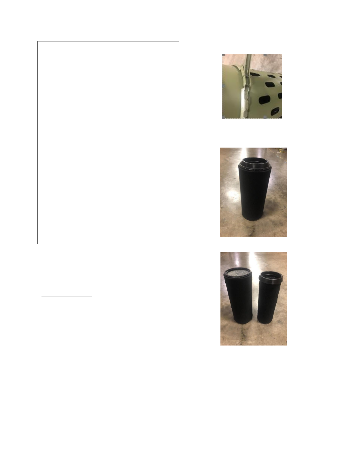
Outer Filter ................................................................................................................................... 5 Microns
Inner Filter ..................................................................................................................................... 1 Micron
Overall Dimensions (H/in x Diameter) .....................................................................................31-1/2” x 14”
Sound Rating @ 3ft .......................................................................................................... High Speed 75 dB
.................................................................................................................................... Medium Speed 69 dB
........................................................................................................................................... Low Speed 65 dB
Air Flow ..................................................................................................................... High Speed 1550 CFM
............................................................................................................................. Medium Speed 1260 CFM
...................................................................................................................................... Low Speed 980 CFM
Filter Cycle (min).................................................................................................................................... 2.06
Cycles per Hour (20’x20’x8’) ……………………………………………………………………………………………… 29.13 Cycles
Motor ................................................................................................................. 115V, 60Hz, 1 PH, 6P, 5.5A
Net Weight ......................................................................................................................................... 31 lbs.
Shipping Weight ................................................................................................................................. 34 lbs.
For Your Own Safety
1. Read and understand instruction manual before installing or operating air cleaner.
2. To reduce the risk of injury disconnect the air cleaner from the power source (unplug) before servicing
or changing filters.
3. If ceiling mounted, bottom of air cleaner must be at least 7 feet above the floor.
4. If ceiling mounted, mounts must be anchored to building structure which will support a minimum of
at least 100 pounds. Never mount to surfaces such as dry wall or false ceiling grids, etc.
5. To reduce the risk of electrical shock, do not expose air cleaner to water or rain.
6. Never duct a machine directly into the air cleaner.
7. To avoid a potentially dangerous situation, do not use this equipment to filter flammable vapors or
smoke. This air cleaner is designed and intended for the filtration of air borne wood dust only. It is
neither designed nor intended for any other purpose whatsoever.
8. Failure to comply may result in serious injury and / or property damage.
The above specifications were current at the time this manual was published, but because of our policy
of continuous improvement, GENERAL reserves the right to change specifications at any time and
without prior notice, without incurring obligations.

Contents of shipping carton:
1 Air Filtration Unit
1 Manual and Warranty Card

Assembly
CAUTION:
THERE IS NO ASSEMBLY REQUIRED FOR THE #10-
1440 AIR FILTRATION UNIT. Remove unit from the
box.
OPERATING INSTRUCTIONS:
1) Plug unit into power source.
2) To turn unit ON/OFF, Press I/O button.
3) To run in “AUTO” mode, using the
infrared sensor, PRESS “AUTO” once unit
is on. The unit will turn on once it senses
particulates in the air and filter, once air
is cleaned, it will shut off.
4) To run in “MANUAL” mode, press “FAN”
once unit is on, and adjust fan speed,
LOW, MEDIUM or HIGH, by pressing the +
or –button for desired fan speed.
5) To set timer,1-12 hours, press “TIME”,
button once unit is on, then press + to
increase hours & - to decrease hours,
until desired number of hours comes up
on screen. Unit will run then shut off at
set time.
6) When running time hits pre-set value, the
display screen will light up indicating the
filter(s) need cleaned/changed. Once
cleaned/changed, press “FILTER” button
to reset preset value (Time).
User can also clean filter before indicator
light comes on. SEE “Cleaning Filters”.

Fig. 2
Fig. 3
Fig.4
Replacement Filters
OPTIONAL FILTERS:
Electrostatic outer filter
Washable electrostatic outer filter
Inner filter
Charcoal filter
HEPA filter
Cleaning/Changing the Filters:
To reduce the risk of injury, disconnect the air
cleaner from the power source (unplug) before
servicing or changing filters. Failure to comply may
cause serious injury!
There are two (2) filters that need to be
cleaned/changed. The outer filter can easily be
removed by disengaging the spring clamp from the
top of the unit. (fig 3:). Now you can simply pull
the filters out.
Once removed from unit, the inner filter (Fig 4.)
can now be pulled out of the outer filter. Both
filters can be blown out with compressed air. The
filters should be replaced depending on the
amount of usage and the environment of your
shop.
Clogged filters will reduce the amount of air
circulation. There is an arrow indicating the air
flow direction on the outer filter. Make sure the
filter is inserted facing the proper direction.

#10-14400 SCHEMATIC:

#10-1440 PART NUMBERS:
PARTS
REFERENCE
DESCRIPTION
SPECIFICATION
QTY.
1
10-1440-1
Barrel
1.000
2
10-1440-2
Locking collar
1.000
3
10-1440-3
Round filter
HEPA/H12
1.000
4
10-1440-4
Eyebolt
M6×20
2.000
5
10-1440-5
Hex nut
GB/T6170/M6
2.000
6
10-1440-6
Cross pan head screw
GB/T818/M5×12
4.000
7
10-1440-7
Cross pan head screw
GB/T818/M4×10
15.000
8
10-1440-8
Power switch
10A/125V
1.000
9
10-1440-9
Cable gland
6P-4
1.000
10
10-1440-10
Power cable
DLC3KEE9S-A-BPS
1.000
11
10-1440-11
Control unit
1.000
12
10-1440-12
Button label
1.000
13
10-1440-13
Round PCB
1.000
14
10-1440-14
Self-tapping screw
GB/T845/ST3.5×6.5/F
8.000
15
10-1440-15
Capacitor
CBB61/250VAC/50/60HZ/14uF
1.000
16
10-1440-16
Cross pan head screw
GB/T818/M4×16
2.000
17
10-1440-17
Arc cover
1.000
18
10-1440-18
Spring washer
GB/T93/4
6.000
19
10-1440-19
Tooth washer
GB/T862.1/4
2.000
20
10-1440-20
Rubber ring
0.500
21
10-1440-21
Rubber ring
2.000
22
10-1440-22
Cover
1.000
23
10-1440-23
Cable
DL1EHB-H-B-P
1.000
24
10-1440-24
Cross pan head screw
GB/T818/M5×8
12.000
25
10-1440-25
Flat washer
GB/T97.1/5
8.000
26
10-1440-26
Jam nut
GB/T889.1/M5
4.000
27
10-1440-27
Draught fan
1.000
28
10-1440-28
Upper bracket
4.000
29
10-1440-29
Upper bracket
4.000
30
10-1440-30
Wiring
ZH1.5
1.000
31
10-1440-31
Hood
1.000
32
10-1440-32
Clapboard
1.000
33
10-1440-33
Silica sealing strip
10×4
1.700
34
10-1440-34
Dust sensor
1.000
35
10-1440-35
Hex nut
GB/T6170/M4
2.000
36
10-1440-36
Bracket
1.000
37
10-1440-37
Big washer
GB/T96.2/8
1.000
38
10-1440-38
Nut
GB/T6170/M8
1.000
39
10-1440-39
Footing
M8×50
1.000
40
10-1440-40
trundle
1.5"
2.000
41
10-1440-41
Cross pan head screw
GB/T818/M6×12
6.000
42
10-1440-42
Collapsible handle
L=138
1.000
43
10-1440-43
Cross pan head screw
GB/T818/M5×10
2.000

10-1000 M1 Wiring Diagram:

Warranty Statement and Policy
Commercial General™ (Green Line) & Excalibur™ (Black Line) branded products: 3 -YEAR LIMITED
WARRANTY All products are warranted for a period of 3 years (36 months) from the date of purchase.
General™ agrees to repair or replace any part or component which upon examination, proves to be
defective in either workmanship or material or parts and labor to the original purchaser during this 3-
year warranty period, subject to the “conditions and exceptions” as listed below. Repairs made without
the written consent of General will void the warranty
EXTEND YOUR WARRANTY: Register your new General™ or Excalibur™ within 60 days of your purchase
and get an extended 2 years, for a total of 5 years, of warranty coverage.
Go to www.general.ca/warranty/registration
DISCLAIMER: Because we are committed to making constant improvements, General™ reserves the
right to make changes to components, parts or features of this unit as deemed necessary, without prior
notice and without obligation to install any such changes on previously delivered units. Reasonable care
is taken at the factory to ensure that the specifications and information in this manual corresponds with
that of the unit with which it was supplied.
TO FILE A CLAIM: To file a claim under our Standard 3 -year Limited Warranty, all defective parts,
components or machinery must be returned freight or postage prepaid to General™, or to a nearby
distributor, repair center or other location designated by General™. For further details call our service
department at 1-844-877-5234 or info@gipowerproducts.com Along with the return of the product
being claimed for warranty, a copy of the original proof of purchase and a “letter of claim” must be
included (a warranty claim form can also be used and can be obtained, upon request, from General™ or
an authorized distributor) clearly stating the model and serial number of the unit (if applicable) and
including an explanation of the complaint or presumed defect in material or workmanship.
CONDITIONS AND EXCEPTIONS: This coverage is extended to the original purchaser only. Prior warranty
registration is not required but documented proof of purchase, i.e. a copy of original sales invoice or
receipt showing the date and location of the purchase as well as the purchase price paid, must be
provided at the time of claim. Warranty does not include failures, breakage or defects deemed after
inspection by General™ to have been directly or indirectly caused by or resulting from; improper use, or
lack of or improper maintenance, misuse or abuse, negligence, accidents, damage in handling or
transport, or normal wear and tear of any generally considered consumable parts or components.
Repairs made without the written consent of General™ will void all warranty. This five-year warranty
does not cover products used for commercial, industrial or educational purposes. The warranty term for
these claims will be limited to a two-year period.
GENERAL sells through distributors only. The specifications listed in GENERAL printed materials and on
official GENERAL website are given as general information and are not binding. GENERAL reserves the
right to effect at any time, without prior notice, those alterations to parts, fittings, and accessory
equipment which they may deem necessary for any reason whatsoever.


This manual suits for next models
2
Table of contents
Other General Water Filtration System manuals
Popular Water Filtration System manuals by other brands

SpectraPure
SpectraPure 100 GPD U.H.E RO/DI Owner's Manual & Installation Instructions

PondXpert
PondXpert Skimmster PXSKIMM01 manual

NatureWater
NatureWater 50877 Operation manual

EHEIM
EHEIM aqua160 Original operating manual

Titan
Titan TOx-5810XTR2-10-54 Owner's manual and installation guide

BRUEL & KJAER
BRUEL & KJAER 1618 manual

Clean Water Systems
Clean Water Systems 7500-REV4 installation guide

Graf
Graf Optimax-Pro Installation and maintenance instructions

Spruce
Spruce AIRaider Installation & operating instructions

Waterdrop
Waterdrop WD-FC-01 owner's manual

ROSEDALE
ROSEDALE DUPLEX 6 Installation, operation and maintenance manual

VITO
VITO VL user manual