9
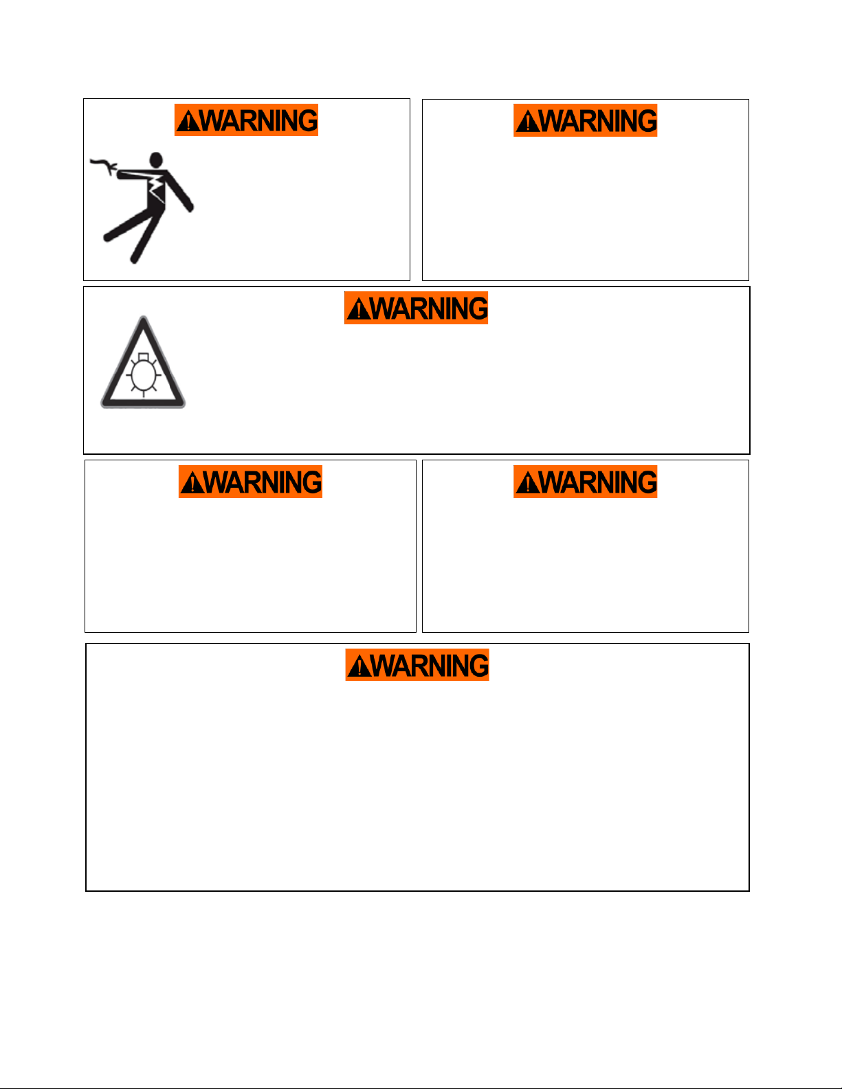
UV Lamp Safety Information
Ultraviolet germicidal irradiation (UVGI) is used for the activation of the PCO Catalyst. The residual
light presents a variety of potential health hazards to humans. These hazards include eye damage,
skin burns, and the potential to cause skin cancer. Because germicidal UV rays are invisible to the
human eye, personnel may be subjected to a hazardous dose of UV without warning. There is no
Occupational Safety and Health Administration standard for exposure to ultraviolet light. UV can be
associated with adverse health effects depending on duration of exposure and wavelength. These
adverse health effects include erythema (sunburn), photokeratitis (a feeling of sand in the eyes), skin
cancer, melanoma, cataracts, and retinal burns. Ideally, activated UV sources should be attended by
knowledgeable personnel at all times.
The UVC lamps in CenterPoint™products do not produce ozone! The lamps provide a minimum
intensity of 775 microwatts/cm2at 10.77 cm to activate the catalyst effectively to maintain tested
performance. Lamps may not be substituted with an unapproved manufacturer. These lamps provide
UV-C light at a wavelength of 254 nm. Despite their appearance to the naked eye, the lamp intensity
will reduce over time. All lamps must be replaced every 16 months (12000 hrs.) of continuous use to
maintain intensity requirements. Lamps provided contain trace amounts of mercury. Lamps include a
Teflon case to encapsulate the lamp and reduce the risk of exposing the consumer and environment
to mercury.
Personal Protective Equipment
While in normal operation, these units will not emit harmful levels of UV radiation to the surrounding
area. When checking for proper lamp connection, you may be exposed to harmful levels of UV
radiation. If you must have the lamps on to check for proper operation, follow these instructions.
•All personnel exposed to UV radiation must wear UV protective glasses.
•All personnel exposed to UV radiation must protect exposed skin with UV resistant clothing.