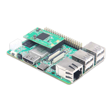
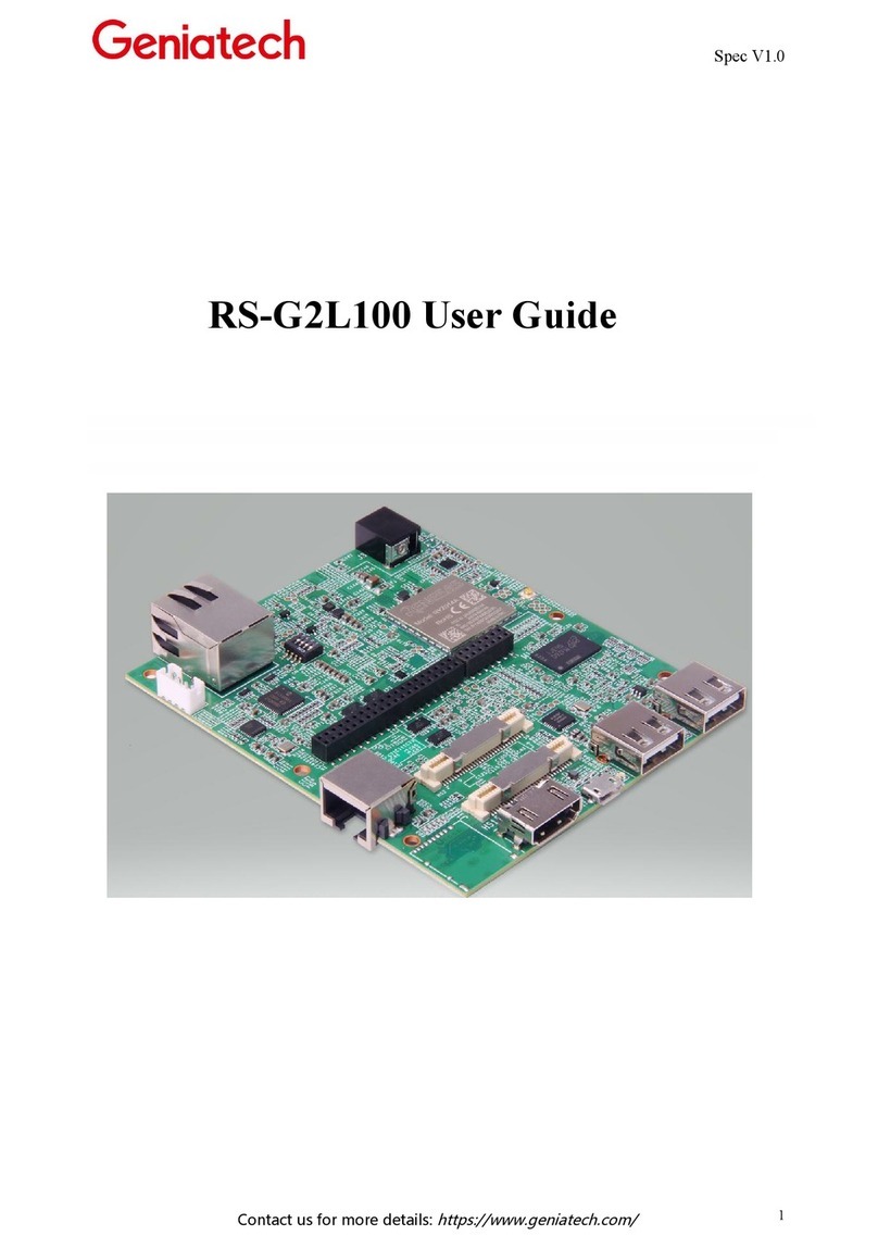
Geniatech RZ-G2L-OSM User manual

Room 02-04, 10/F, Block A, Building 8, Shenzhen International Innovation Valley, Dashi Road,
Nanshan District, Shenzhen, Guangdong, China
Emai: support@geniatech.com Tel: (+ 86) 755 86028588
3
Content
1. RZG2L-OSM Operating System .........................................................................................................................................4
2. Linux System Installation ................................................................................................................................................... 4
3. Function Description ...........................................................................................................................................................4
3.1 Hardware interface schematic ...................................................................................................................................4
3.2 WIFI Connection ...................................................................................................................................................... 6
3.3 Ethernet ...................................................................................................................................................................11
3.4 TF card ....................................................................................................................................................................11
3.5 MIPI Screen & Touch .............................................................................................................................................13

Room 02-04, 10/F, Block A, Building 8, Shenzhen International Innovation Valley, Dashi Road,
Nanshan District, Shenzhen, Guangdong, China
Emai: support@geniatech.com Tel: (+ 86) 755 86028588
4
1. RZG2L-OSM Operating System
RZG2L-OSM is currently supported by Linux
2. Linux System Installation
Installation steps are described in the <RZG2L-OSM_yocto> burn-in instructions document>.
3. Function Description
3.1 Hardware interface schematic

Room 02-04, 10/F, Block A, Building 8, Shenzhen International Innovation Valley, Dashi Road,
Nanshan District, Shenzhen, Guangdong, China
Emai: support@geniatech.com Tel: (+ 86) 755 86028588
5
3.1.1 Test preparation:
(1)Serial cable*1, connect to the serial port (J11), open the serial debugging software to select COM port and baud
rate 115200
Pin NO
Definition
1
UART_RX2
2
GND
3
UART_TX2
4
NC

Room 02-04, 10/F, Block A, Building 8, Shenzhen International Innovation Valley, Dashi Road,
Nanshan District, Shenzhen, Guangdong, China
Emai: support@geniatech.com Tel: (+ 86) 755 86028588
6
(2)After power on and boot up is complete, enter root to log in
3.2 WIFI Connection
3.2.1 Test preparation: two WiFi antennas, connected as shown

Room 02-04, 10/F, Block A, Building 8, Shenzhen International Innovation Valley, Dashi Road,
Nanshan District, Shenzhen, Guangdong, China
Emai: support@geniatech.com Tel: (+ 86) 755 86028588
7
3.2.2 To connect to the environment without encrypted WiFi, enter the following command
(1) ifconfig mlan0 up Turn on the WiFi node, and then enter ifconfig to see if the node is on

Room 02-04, 10/F, Block A, Building 8, Shenzhen International Innovation Valley, Dashi Road,
Nanshan District, Shenzhen, Guangdong, China
Emai: support@geniatech.com Tel: (+ 86) 755 86028588
8
(2) vi /etc/wpa_supplicant.conf Enter and press ito enter edit mode and change the configuration to the following
network={
ssid="TP-LINK_5G_20EE" (this is set to the WiFi name in the environment)
key_mgmt=NONE
}
(3)When finished editing, press esc, then type :wq and enter to save the configuration
(4)Input wpa_supplicant -B -c /etc/wpa_supplicant.conf -imlan0 -Dnl80211,wext command
(5)Then enter the udhcpc -i mlan0 command to dial the number
(6)Type ifconfig to see if mlan0 gets IP, if it has IP, it is successfully connected.

Room 02-04, 10/F, Block A, Building 8, Shenzhen International Innovation Valley, Dashi Road,
Nanshan District, Shenzhen, Guangdong, China
Emai: support@geniatech.com Tel: (+ 86) 755 86028588
9
3.2.3 Encrypted WiFi in the connected environment
(1) ifconfig mlan0 up Enter this command to turn on the WiFi node
(2) vi /etc/wpa_supplicant.conf enter the configuration and press ito enter edit mode. Set the following
network={
ssid="111" (the name of the encrypted WiFi in the environment)
key_mgmt=WPA-PSK
psk="12345678" (WiFi password)
}

Room 02-04, 10/F, Block A, Building 8, Shenzhen International Innovation Valley, Dashi Road,
Nanshan District, Shenzhen, Guangdong, China
Emai: support@geniatech.com Tel: (+ 86) 755 86028588
10
(3)Press esc to exit editing, type :wq and enter to save
(4)input wpa_supplicant -B -c /etc/wpa_supplicant.conf -imlan0 -Dnl80211,wext command
(5)Then enter the udhcpc -i mlan0 command to dial the number
(6)Enter ifconfig to see if mlan0 gets an IP, and if it has an IP, it is successfully connected

Room 02-04, 10/F, Block A, Building 8, Shenzhen International Innovation Valley, Dashi Road,
Nanshan District, Shenzhen, Guangdong, China
Emai: support@geniatech.com Tel: (+ 86) 755 86028588
11
3.3 Ethernet
3.2.1 Test tool preparation: network cable*1
(1)Power up the board and connect the network cable to the network port
(2)After the system has finished booting, wait about 5 seconds and type ifconfig to see if the eth0 node has an IP
(3)Obtain IP means successful connection
3.4 TF card
Note: the system cannot start when the TF card is inserted, it needs to be inserted after the start-up is completed
3.4.1 Test tool preparation: a TF card
(1)Insert the TF card into the (hot-swappable) card slot
(2)fdisk -l View partition

Room 02-04, 10/F, Block A, Building 8, Shenzhen International Innovation Valley, Dashi Road,
Nanshan District, Shenzhen, Guangdong, China
Emai: support@geniatech.com Tel: (+ 86) 755 86028588
13
3.5 MIPI Screen & Touch
(1)Connect the MIPI screen as shown in the diagram
(2)Power on and start, observe whether there is backlight

Room 02-04, 10/F, Block A, Building 8, Shenzhen International Innovation Valley, Dashi Road,
Nanshan District, Shenzhen, Guangdong, China
Emai: support@geniatech.com Tel: (+ 86) 755 86028588
17
MIPI-DSI Connector (J28)
I2C TOUCH Connector (J36)
Pin NO
Definition
Pin NO
Definition
1
NC
21
DSI_DATA3_P
2
VCC_LCD0
22
GND
3
IOVCC_1.8V/3.3V
23
NC
4
GND
24
NC
5
MIPI_DSI_nRST
25
GND
6
NC
26
NC
7
GND
27
PWMO
8
DSI_DATA0_N
28
NC
9
DSI_DATA0_P
29
NC
10
GND
30
GND
11
DSI_DATA1_N
31
VCC1_LED-
12
DSI_DATA1_P
32
VCC1_LED-
13
GND
33
NC
14
DSI_CLOCK_N
34
NC
15
DSI_CLOCK_P
35
NC
16
GND
36
NC
17
DSI_DATA2_N
37
NC
18
DSI_DATA2_P
38
NC
19
GND
39
VCC1_LED+
20
DSI_DATA3_N
40
VCC1_LED+
Pin NO
Definition
1
I2C_A0_SCL
2
I2C_A0_SDA
3
VDD_3V3
4
TP_nRST_C
5
TP_nINT_C
6
GND
Table of contents
Other Geniatech Computer Hardware manuals