GENIUS POWER GW-3212 20A User manual

DC to DC
BATTERY CHARGER
User’s Manual
Model No. GW-3212 20A
GW-3212 30A
GW-3212A 30A
GW-3212B 30A
GW-3212D 30A
GW-3212F 30A

1
age.2
age. 6
age. 7
e. 8
e. 9
e. 10~11
e. 14
e. 15
Table of Contents
1. Overview.......................................................P
3. Recommendation of Battery Capacity..........P
4. Safety Instructions and Warnings.................P
5. Maintenance.................................................Pag
6. Mounting The Charger..................................Pag
7. Wire Connection...........................................Pag
8. Display during operation...............................Page. 12~13
9. The Error Code.............................................Pag
10. Troubleshooting .........................................Pag
2. Specification..................................................Page.3~5
GW-3212 DC to DC Battery Charger
Thank you for purchasing our DC to DC Battery Charger.
Properly used, this product will provide years of reliable
service. Please read this manual carefully, understand
and comply with all instructions before use.

2
Power Input Auxiliary Battery
Terminal
Charger ON/OFF Control Pin(ACC)
1.Overview
FAN
Charger Status Display
Mounting
Holes
Function
Switch
9-32VDCBUCK-BOOSTCHARGER
Power lnput ACC B a t t e r y
++
- -
GENIUS POWER
9-32VDCBUCK-BOOSTCHARGER
Power lnput ACC B a t t e r y
++
- -
GENIUS POWER
Remote
Remote
FAN
GW-3212B 30A Only
GW-3212B 30A Only
GW-3212-REMOTE
Charger Status
Display
Remote
GP-169(Remote)
Function
Switch

3
2. Specification
Power
Input
DC 9~32V
Current Range DC 30A DC 40A(max.)
Efficiency(%) 92%
DC
Output
Battery Charging
Type
Lead acid GELAGM
Selectable
Charging Current Max. 30A
20A
Charging Voltage DC14.4V DC14.7V DC14.1V
Floating Charging Voltage
DC13.3V DC13.6V DC13.1V
Charging
Mode
Step 1 Constant-Current
Step 2 Constant-Voltage
Step 3 Floating
Protection
DC Input High Voltage >32V
DC Input Low Voltage <9V
DC Input Polarity Protection
YES(By Fuse)
DC Input Fuses 20A*2pcs
15A*2pcs
DC Output Short Protection
YES
Overtemp Protection YES
Display
NA
Function Selection By Switch
Cooling Temperature Controlled Fan
Wire Connection Terminal With M4 Screw
Dimension 180(W)*134(H)*60(D)mm
Weight 385g
Voltage Range
Mode No.
–20°C ~ 65°C / – 4°F~149°F
Operating Temperature Range –20°C~ 40°C / –4°F~104°F
Storage Temperature Range
GW-3212 20A GW-3212 30A GW-3212B 30A
GW-3212A 30A
5 / 10 / 15 / 20 / 30A
Selectable
Input/
Output
Terminal
Power Input(+)
Power Input(-)
ACC Input
Battery Connect (+)
Battery Connect (-)
Terminal block
LCD Display
LCD Display
Charging Information
Battery Voltage
Charging Current
Charging Information
Battery Voltage
Charging Current
RJ45
10m Max.
Remote
Unit
(GP-169) Connector Type
Wire Length

4
2.1. Specification
Power
Input
DC 9~32V
Current Range DC 40A(max.)
Efficiency(%) 92%
DC
Output
Battery Charging
Type
Lead acid GELAGM
Selectable
Charging Current Max.
Charging Voltage DC14.4V DC14.7V DC14.1V
Floating Charging Voltage
DC13.3V DC13.6V DC13.1V
Charging
Mode
Step 1 Constant-Current
Step 2 Constant-Voltage
Step 3 Floating
Protection
DC Input High Voltage >32V
DC Input Low Voltage <9V
DC Input Polarity Protection
YES(By Fuse)
DC Input Fuses 20A*2pcs
DC Output Short Protection
YES
Overtemp Protection YES
Display
Function Selection By Switch
Cooling Temperature Controlled Fan
Wire Connection Terminal With M4 Screw
Dimension 180(W)*134(H)*60(D)mm
Weight 385g
Voltage Range
Mode No.
–20°C ~ 65°C / – 4°F~149°F
Operating Temperature Range –20°C~ 40°C / – 4°F~104°F
Storage Temperature Range
GW-3212D 30A
5 / 10 / 15 / 20 / 30A
Selectable
Input/
Output
Terminal
Power Input(+)
Power Input(-)
ACC Input
Battery Connect (+)
Battery Connect (-)
Terminal block
LCD Display
Charging Information
Battery Voltage
Charging Current
LiFePO4
DC14.6V
N/A
N/A

5
2.2. Specification
Power
Input
DC 9~32V
Current Range DC 40A(max.)
Efficiency(%) 92%
DC
Output
Battery Charging
Type Selectable
Charging Current Max.
Charging Voltage
Floating Charging Voltage
Charging
Mode
Step 1 Constant-Current
Step 2 Constant-Voltage
Step 3
Protection
DC Input High Voltage >32V
DC Input Low Voltage <9V
DC Input Polarity Protection
YES(By Fuse)
DC Input Fuses 20A*2pcs
DC Output Short Protection
YES
Overtemp Protection YES
Display
Function Selection By Switch
Cooling Temperature Controlled Fan
Wire Connection Terminal With M4 Screw
Dimension 180(W)*134(H)*60(D)mm
Weight 385g
Voltage Range
Mode No.
–20°C ~ 65°C / – 4°F~149°F
Operating Temperature Range –20°C~ 40°C / – 4°F~104°F
Storage Temperature Range
GW-3212F 30A
5 / 10 / 15 / 20 / 30A
Selectable
Input/
Output
Terminal
Power Input(+)
Power Input(-)
ACC Input
Battery Connect (+)
Battery Connect (-)
Terminal block
LCD Display
Charging Information
Battery Voltage
Charging Current
LiFePO4
DC14.6V
N/A
N/A

6
3. Recommendation of Lead Acid
Battery Capacity
Attention :
1.Auxiliary battery capacity : it recommends 4 times of max.
charging current. According to battery manufacturer, it can
maximize the battery life span if to charge battery with
current less than 0.25C.
e.g. 1C = the battery capacity
1C = DC12V / 80AH, 0.25C = 20A
2.Please charge the battery at least once every 3 months
3.Battery voltage checking:
Battery Voltage Battery Status
>DC13V
<DC12.4V
Battery is full
need to recharge battery
Remark: Above DC13V is just a reference, please check
the specifications provided by the battery supplier for
exact data.
4.Auxiliary battery: Only apply to 12V battery. It will cause
the battery charger damage if use different voltage battery.
Charging Current
Auxiliary DC12V Battery Capacity (Min.)
5A 20AH
10A 40AH
15A 60AH
20A 80AH
30A 120AH
No exceed charging current 0.25C to maximize the battery life

4.Safety Instructions and Warnings
1.Dry- Do not allow water to drip or splash on the charger
2.Cool- Ambient air temperature should be between 0 and 40°C,
the cooler the better.
3.Safe- Do not install in a battery compartment or other areas
engine compartments.
4.Ventilated- Allow at least one inch of clearance around the
Ensure the ventilation openings on the rear and front of the unit
are not obstructed.
5.Dust- Do not install the charger in a dusty environments where
These dust can be pulled into the unit when the cooling fan is
operating.
6.Close to batteries- Avoid excessive cable lengths but do not
install the charger in the same compartment as batteries.
Your cables should be as short as possible enough to handle the
required current in accordance with the electrical codes or
regulation application.
The Charger should be installed in a location that meets
the following requirements.
7

gases produced by the battery.
These gases are very corrosive and prolonged exposure also will
damage the charger.
Also do not mount the charger where it will be exposed to the
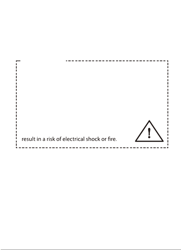
WARNING!
Shock Hazard. Before proceeding further, carefully check
that the charger is NOT connected to any batteries, and
that all wiring is disconnected from any electrical sources.
Make sure all the wire connection are tight.
Loose connections could result overheat in a potential
hazard.
Do not open or disassemble the charger.
Attempting toservice the unit yourself may
5. Maintenance
Very little maintenance is required tokeep your charger
operating properly.
You should clean the exterior of the unit periodically with a
damp cloth to prevent accumulation of dust and dirt.
At the same time, tighten the screws on the power input ,
battery and ACC terminals.
8

9
6. Mounting The Charger
6-1.For installing in a car or boat environment, the charger
should be mounted vertically. This provides the best
thermal performance and drip protection.
6-2.Use the base of the charger as a mounting template to
mark the positions
of the fixing
screws.
Unit: mm
7. Wire Connection
Use Car Ignition
Switch To Start
The Charger
P C
GENIUS POWER
P C
GENIUS POWER
GW-3212-REMOTE
For GW3212B Only
GW3212-Remote

Caution:Please pay attention to polarity while connect wire.
Wrong connection will cause the product damage.
READY TO CHARGE
LEAD ACID MODE
3-1. Press the Function Switchfor 3 seconds in charging mode,
buzzer sounds and gets into
stand-by mode.
3-2. Press 2times consecutively the Function Switch in
stand-by status to change the charging mode.
BATTERY TESTING
VI : ERROR
WRONG BATTERY
LEAD ACID MODE
Vb: 14.4V I:20.0A
LEAD ACID MODE
Vb: 14.4V I:30.0A
8. Display During Operation
:
Operation:
1.Wire ACC and Vehicle Ignition Switch
2.Use Start / Vehicle battery to charge the Auxiliary Battery
via Vehicle Ignition Switch.
The battery charger is powered when Ignition Switch turn to
“ON” and start to charge battery.
The battery charger stop charging when Ignition Switch turn to
“LOCK”, and insulate the Start/Vehicle battery for power saving.
Step 1:
Step 2:
Understanding the display information:
When detect Input and Battery Voltage,
it shows:
If input voltage is out of range, it shows:
If Aux. battery voltage is out of range,
it shows:
Please refer toStep 3 if Input Voltage &
Battery Voltage operate normally
Step 3:
*When Battery Charging Start, display is
showing as below:
"LEADACID MODE" :
Charging Lead Acid Battery
"Vb: 14.4V" : Battery Voltage
"I:20.0A", "I:30.0A" : Battery Charging Current
*Battery Charging Stop or Change Charging Mode:
When the charger power up, the back light on.
8.1 For GW-3212 20A / GW-3212 30A/ GW-3212(A)(B)(D) 30A
10

AUX BATT 14.6V
* Battery Voltage Display Function
4-2-1. It gets into Sleep Mode when the Ignition Switch off
but battery is connected.
4-2-2. Display shows Battery
Voltage if to press the Function
4-2-3. It moves back to Sleep Mode again after 10 seconds.
4-2-4. Press the Function Switchin Sleep Mode and battery
voltage is less than 10.5V, buzzer sounds for 10
seconds, then moves back to Sleep Mode again.
READY TO CHARGE
LEAD ACID MODE
READY TO CHARGE
AGM MODE
READY TO CHARGE
GEL MODE
Charging Lead Acid Battery (Default)
Charging Voltage: DC14.4V
Floating Charging Voltage: DC13.3V
Charging AGM Battery
Charging Voltage: DC14.7V
Floating Charging Voltage: DC13.6V
Charging GEL Battery
Charging Voltage: DC14.1V
Floating Charging Voltage: DC13.1V
3-3. Press the Function Switch for 3 seconds in stand-by mode,
buzzer sounds and move back to Charging mode, the setting
will be recorded as default for next charging.
LEAD ACID MODE
Vb: 13.3V I:01.0A
AGM MODE
Vb: 13.6V I:01.0A
GEL MODE
Vb: 13.1V I:01.0A
Step 4:
* Battery Charging Finish
4-1-1. While display shows Vb (Battery Voltage) consecutively
same as voltage as following, it means battery charger is in
floating mode and battery is fully
charged.
LEADACID MODE: Vb:13.3V
AGM MODE: Vb:13.6V
GEL MODE: Vb:13.1V
Switch in Sleep Mode
LiFePO4 MODE
Vb: 14.6V I:0.0A
LiFePO4 MODE: Vb:14.6V
LiFePO4
OTHERS: 13V
11

READY TO CHARGE
AGM MODE
READY TO CHARGE
GEL MODE
READY TO CHARGE
Ic:30A MAX
LEAD ACID MODE
Vb: 14.0V I:30.0A
8.2 For GW-3212A-30A / GW-3212B-30A / GP-169 (Remote) /
GW-3212D-30A
Step 1: When battery in charging, display shows:
Press the Function Switch continuously for 3 seconds, then release
the Function Switch after buzzer sound, it stops charging and gets into
the voltage setting mode.
display shows: READY TO CHARGE
LEAD ACID MODE
READY TO CHARGE
LEAD ACID MODE
Step 2:
Press 2 times consecutively the Function Switch under the voltage
setting mode, it can switch three battery charging modes circularly.
* if LiFePO4 battery, display shows:
* if Lead Acid battery, display shows:
* if AGM battery, display shows:
* if GEL battery, display shows:
Press the Function Switch for 3 seconds
once the battery charging mode selection is
completed, and release the Function Switch
after buzzer sounds.Then the setting is saved.
READY TO CHARGE
LiFePO4 MODE
12
READY TO CHARGE
Ic:30A MAX
READY TO CHARGE
LiFePO4 MODE
(For GW-3212F 30A)

LEAD ACID MODE
Vb: 14.0V I:30.0A
Press the Function Switch for 3 seconds
once the charging current selection is
completed,and release the Function Switch
after buzzer sounds.
It starts charging, and display shows:
READY TO CHARGE
Ic:30A MAX
READY TO CHARGE
Ic:20A MAX
READY TO CHARGE
Ic:15A MAX
READY TO CHARGE
Ic:10A MAX
READY TO CHARGE
Ic: 5A MAX
Step 3:
Press 2 times consecutively the Function Switch under the current setting
mode,it can switch between five max. charging currents circularly.
* if 30A, it shows:
* if 20A, it shows:
* if 15A, it shows:
* if 10A, it shows:
* if 5A, it shows:
13

14
9. The Error Code
(See table description below for more information)
zer operate
rt beep
ort beeps
ort beep
hort beeps
V I : E R ROR
The Display Code
Description How buz
Input voltage error Continuous Alarm
B A T T E R Y
W
R ONG
B A T T E R Y
W
R ONG
B A T T E R YON
MP .T E RORRE
Low Battery Voltage
a sho
High Battery Voltage two sh
Battery disconnection a sh
Temp deviant
three s

Problem Solution
No Charging
(no display)
Check voltage & current
Please change by the
experienced engineer
Check connection and wires
No Charging
(with display)
No charging after
prolonged use
Check voltage & current
Check if poor wiring
Check if poor battery condition
or wrong voltage
Check if wrong voltage
Improve ventilation
Reduce ambient temperature
10. Troubleshooting
BuzzerPossible Cause
No beep
Low input voltage
Input fuse burned
Wrong wire connection
Long beep Input voltage deviant
1 short beep
1 short beep
2 short beeps
3 short beeps
Battery is not connected
Low battery voltage
High battery voltage
Over temperature
15
This manual suits for next models
5
Table of contents