Gentner AP IR User manual

Introduction.....................................................3
Unpacking..............................................................................................4
Warranty Instructions....................................................................................4
Installation......................................................7
Operation.........................................................9
Remote Control Buttons.....................................................................................11
Place a Call............................................................................................................11
End a Call................................................................................................................11
Adjust the Volume in the Room.....................................................................11
Mute Microphones........................................................................................... .11
Turn off Mute........................................................................................................11
Access Features from a PBX.........................................................................11
Redial the Last Telephone Number Dialed..............................................11
Dial a Number Stored in Speed Dial............................................................12
Customize your AP IR Remote Control System......................................12
Programming.................................................13
Baud Rate.................................................................................................................13
Speed Dial................................................................................................................14
Telephone Device................................................................................................14
Mute............................................................................................................................15
Volume.......................................................................................................................16
Volume Range/Step Size...................................................................................18
Hook Flash...............................................................................................................18
Reset to Default......................................................................................................18
Appendices....................................................19
Specifications.........................................................................................................19
Warranty.........................................................................................................20
FCC Part 15 Compliance...................................................................................21
able of Contents
T
TECHNICAL SUPPORT: 1.800.283.5936 (USA) OR 1.801.974.3760
1

TECHNICAL SUPPORT: 1.800.283.5936 (USA) OR 1.801.974.3760
2

1
TECHNICAL SUPPORT: 1.800.283.5936 (USA) OR 1.801.974.3760
3
The AP IR Remote Control System is designed to allow easy operation
of all your Audio Perfect products from your desk or conference table,
rather than from the front panel of your Gentner audio conferencing
products.
It is made up of two components, the handheld infrared transmitter
(remote control) and the base station infrared receiver. The transmitter
is used to operate or customize the many features of the Audio Perfect
system, such as: connect, disconnect, dial a telephone number, redial,
store speed dial numbers, activate speed dial, hook flash, adjust
volume, and mute the microphones.
The AP IR Remote functions with an AP400 stand-alone system, an
AP400/AP800 combination, or it may be used with an AP800/AP10
combination. The default programming may be easily customized to fit
your needs by simply pressing certain key sequences on the transmitter
unit. In the event of a power outage, the new programming will be
stored in the receiver’s memory and will not be lost or altered.
Introduction
Congratulations!
TECHNICAL SUPPORT: 1.800.283.5936 (USA) OR 1.801.974.3760
INTRODUCTION • UNPACKING / WARRANTY INSTRUCTIONS
4
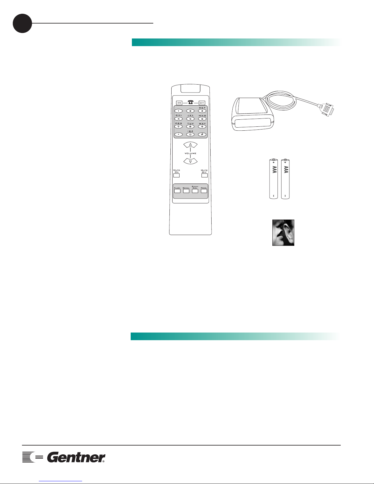
Please check that the following was received with your shipment.
Gentner Communications is not responsible for product damage incurred during
shipment. You must make claims directly with the carrier. Inspect your shipment
carefully for obvious signs of damage. If the shipment appears to be damaged,
retain the original boxes and packing material for inspection by the carrier. Contact
your carrier immediately.
Unpacking
Warranty
Instructions
Please register your Audio Perfect Infrared Remote System online by
visiting Gentner Technical Support on the World Wide Web at
www.gentner.com.
When your product is properly registered, Gentner Communications will
be able to serve you better should you require technical assistance or
desire to receive upgrades, new product information, etc.
ABC
Audio Perfect® Infrared
Remote Control
AP REMOTE
Manual
Infrared
Remote
Transmitter
Mute
Status
Infrared Remote Receiver
Batteries

2
TECHNICAL SUPPORT: 1.800.283.5936 (USA) OR 1.801.974.3760
INSTALLATION 5
Installation is simple, only requiring plugging the AP IR Remote
Receiver into the RS232 connector located on the back of the
AP400 or AP800 unit.
Located on the AP IR Remote Receiver are two LEDs—STATUS and
MUTE. The STATUS LED will glow red when the receiver is
connected to the AP product indicating the system is ready for a
valid command. When a button is pressed, the STATUS LED flashes
rapidly indicating a command has been received.
When the MUTE ON button is pressed, the MUTE LED will blink on
and off indicating the system is in a muted state.
Installation
5 W, 4 to 16 Ohm
Speaker Connection
Analog
Telephone
Line
AP400
=
Microphone
Telephon
e
Set
Video
CODEC
VCR
3241
(Optional)
Tape Player
External Power Amp
(Optional)
Mute
Status
AP IR Receiver
Mute
Status
AP IR Remote Control Receiver

INSTALLATION
TECHNICAL SUPPORT: 1.800.283.5936 (USA) OR 1.801.974.3760
6

3
TECHNICAL SUPPORT: 1.800.283.5936 (USA) OR 1.801.974.3760
OPERATION • GETTING STARTED 7
Getting Started
Once your remote is connected to your Audio Perfect system and the
STATUS LED is lit, it is time to start using your remote control. Operation
is easy and straight forward. Please consult the diagram on the follow-
ing page to understand how each button on your remote works.
If you push a button and there is no response from the system, check to
ensure that both the AP device and the receiver are connected at the
same baud rate. See page 13 for instructions on how to program the
baud rate.
Operation
OPERATION • REMOTE CONTROL BUTTONS
TECHNICAL SUPPORT: 1.800.283.5936 (USA) OR 1.801.974.3760
8
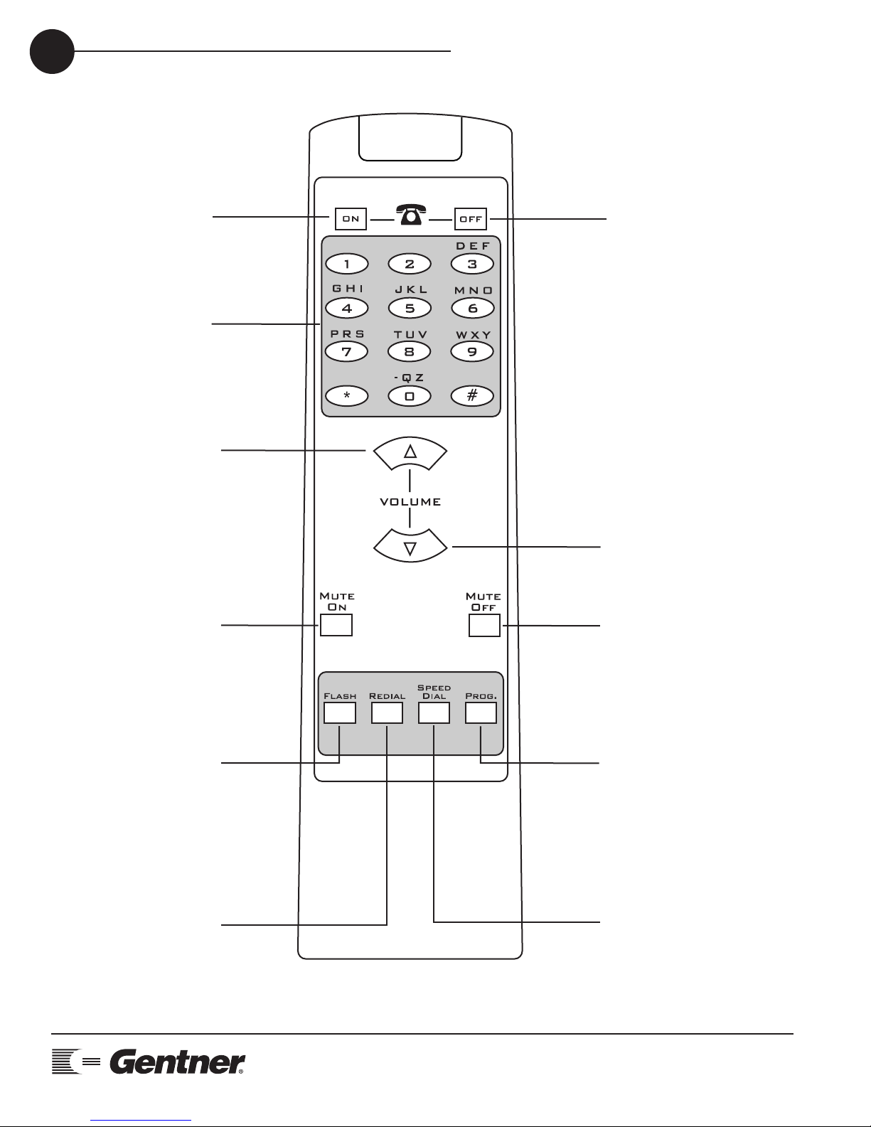
TELEPHONE ON
(green) button
Press to get a dial tone.
TELEPHONE OFF
(red) button
Press to end a call.
NUMBER buttons
Use these buttons to
dial telephone numbers
and to program
functions.
VOLUME UP button
Press to raise the
volume in the room.
VOLUME DOWN button
Press to lower the volume
in the room.
MUTE ON button
Press to mute all
microphones in the
room (default). May be
programmed to mute
specific microphones
in the room.
MUTE OFF button
Press to turn mute
function off.
FLASH button
Provides a hook flash
for accessing features
on your PBX. Please
consult your PBX
owner's manual for
specific instructions
regarding your
individual telephone
system.
REDIAL button
Press to dial the last
telephone number.
SPEED DIAL button
Press to dial telephone
numbers that have
been programmed into
the SPEED DIAL
function. See
Programming section,
page 14.
PROGRAM button
Press for two seconds
to enter PROGRAM
mode. See
Programming section,
page 13.
ABC

TECHNICAL SUPPORT: 1.800.283.5936 (USA) OR 1.801.974.3760
OPERATION • REMOTE CONTROL BUTTONS 9
While within 25-40 feet of the receiver, point the remote control toward
the receiver and press the buttons to operate.
•To Place a Call
Press TELEPHONE ON (green) button.
Wait to hear dial tone.
Dial telephone number using dial pad. Or, press SPEED DIAL and the
location of the speed dial number.
•To End a Call
Press TELEPHONE OFF (red) button.
•To Adjust the Volume in the Room
Press VOLUME UP button to raise the volume.
Press VOLUME DOWN button to lower the volume.
•To Mute Microphones
Press MUTE ON button.
MUTE LED will flash on receiver when the MUTE function is active.
This function mutes all microphones in the room. To customize mute
feature, see Programming section, page 15.
•To Turn off Mute
Press MUTE OFF button.
MUTE LED on receiver will turn off when mute function is off.
•To Access Features from a PBX
Press FLASH button.
Please consult your PBX owner’s manual for specific requirements of
your individual phone system.
Remote Control
Buttons
ABC

HOW TO PLACE A CALL
TECHNICAL SUPPORT: 1.800.283.5936 (USA) OR 1.801.974.3760
10
•To Redial the Last Telephone Number Dialed
Press REDIAL button.
•To Dial a Number Stored in Speed Dial
Press SPEED DIAL button. Select location (0-9) of speed dial number.
Note: In order for the Speed Dial function to work, a telephone
number must be programmed into the Number buttons. Please see
Programming section, page14.
•To Customize your AP IR Remote Control System
Follow instructions beginning on page 13 to customize your AP IR
Remote Control System to fit your specific conferencing needs.
Table of contents
Other Gentner Remote Control manuals


