manuals.online logo
Brands
  1. Home
  2. •
  3. Brands
  4. •
  5. Genuine Shurco
  6. •
  7. Batteries Charger
  8. •
  9. Genuine Shurco Battery Box & Trickle Charger User manual

Genuine Shurco Battery Box & Trickle Charger User manual

Installation Instructions - Battery Box & Trickle Charger P/N 1119781 Rev. B
Item Part # Description
1. 1119783 Battery Box Bottom - Trickle
2. 1117734 Battery Box Top
3. 1117740 Battery Box Hold Down Bracket
4. 1117739 Battery Box Front Bracket
5. 1117741 Battery Clip
6. 1704618 Battery Charging Module
7. 1704161 Solar Gel Battery
8. 1700381 Cap Screw - 1/4” x 1”
9. 1700408 Hex Nut - 1/4”
10. 1700427 Flat Washer - 1/4”
11. 1700436 Lock Washer - 1/4”
12. 1704152 Dome Nut - 1/2”
13. 1704187 Lock Nut - 1/2”
14. 1704354 Modified-Reset Circuit Breaker - 40Amp
15. 1703244 Ring Terminal - 6 Ga. x 3/8” Stud
16. 1704154 Parallel Connector - 16-14 Ga. #6
17. 1703327 Button Hd. Cap Screw - 1/4” x 5/8”
18. 1702654 Round Hd. Machine Screw - #10 x 1”
19. 1702653 Nut/Machine Screw w/Washer - #10
20. 1704238 Button Hd. Cap Screw - 1/4” x 1 1/2”
21. 1118250 Plastic Washer - Orange
22. 1704263 Nylon Shoulder Washer - 1/4”
23. 1704310 Flat Bottom Washer - 1/4”
24. 1704311 Snap-Cap - 12-12 Black
25. 1700400 Self-Tapping Screw - 3/8” x 1”
26. 1700434 Lock Washer - 3/8”
27. 1700407 Hex Nut - 3/8”
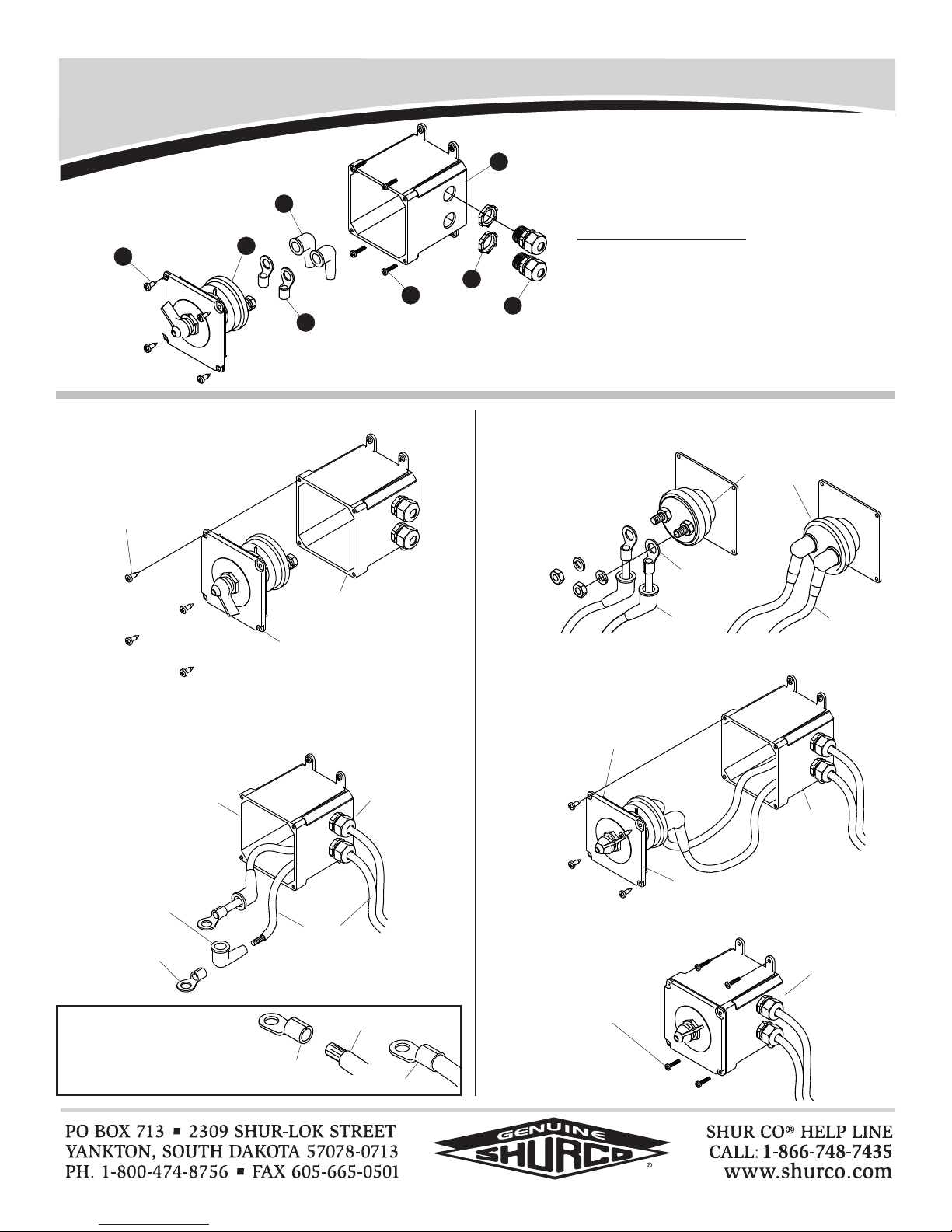
STEP 2: Fasten battery clip and circuit breaker to battery with
1/4” cap screws, flat washers, lock washers and nuts
as shown. Fasten circuit breaker with nut provided.
STEP 1: Using either bottom holes or back holes in battery box
bottom as a guide, mark hole locations on trailer. Drill
5/16”holesandfastenbatteryboxbottomtotrailerwith
3/8” x 1” self-tapping screws, lock washers and nuts.
Battery Box Bottom Battery Clip & Circuit Breaker
NOTE: Install backer plate if trailer wall is less than 1/8” thick.
1
7
6
10
4
3
2
8
9
11
12
14
15
16
17
18
19
26
27
25
10
13
10
11
FASTENER
SUPPLIED
W/CIRCUIT
BREAKER
3/8” X1” SELF-
TAPPING SCREW
BATTERY BOX
BOTTOM
3/8”
NUT
3/8” LOCK
WASHER
1/4” FLAT
WASHER
1/4” LOCK WASHER
1/4” X1”
CAP SCREW
BATTERY CLIP
CIRCUIT BREAKER
BATTERY
1/4” NUT
SUPPLIED
W/CIRCUIT
BREAKER
8
8
10
10
11
9
11
20
23
22
21
24
911
9
10
11
8
9
Installation Instructions - Battery Box & Trickle Charger P/N 1119781 Rev. B
STEP 3: Secure dome nut strain reliefs to battery box bottom
with 1/2” lock nuts.
STEP 6: Secure battery box top to battery box bottom with 1/4”
x 5/8” cap screws and lock washers.
Dome Nuts & Hold-Down Brackets
Battery Box Top
Battery Charging Module
STEP 5: Place battery in battery box bottom. Install hold down
bracketandfrontbracketwith1/4”x 1” cap screws, flat
washers, lock washers and nuts.
Battery & Brackets
STEP 4:
Fastenbatterychargingmoduletohold-downbracketwith
#10x1”machinescrewsandnut/washers.Install1/4”x1
1/2”buttonheadcapscrew,flatbottomwasher,shoulder
washers,orangeplasticwasher,flatwasher,hexnut,lock
washer, second hex nut and snap cap as
shown.
DOME NUT
BATTERY BOX
BOTTOM
1/2” LOCK NUT
BATTERY BOX
BOTTOM ASSEMBLY
FULLY ASSEMBLED
BATTERY
BOX TOP
BATTERY
CHARGING
MODULE
#10 X1” MACHINE SCREW
#10 NUT/WASHER
1/4” X5/8” BUTTON
HEAD CAP SCREW
1/4” LOCK
WASHER
FRONT BRACKET
HOLD-DOWN BRACKET/
BATTERY CHARGING
MODULE ASSEMBLY
BATTERY
BATTERY BOX
BOTTOM
1/4” X1” CAP SCREW
1/4” LOCK
WASHER
1/4” X1”
CAP SCREW
1/4” FLAT
WASHER
1/4” FLAT
WASHER
1/4” NUT
1/4” X1 1/2”
BUTTON HD
CAP SCREW
SNAP CAP
1/4” FLAT
BOTTOM
WASHER
1/4” NYLON
SHOULDER
WASHER
ORANGE
PLASTIC
WASHER
1/4” FLAT
WASHER
1/4”
HEX
NUT 1/4” LOCK
WASHER
1/4”
HEX
NUT
NOTE: Go to
wiring instructions
on next page.
HOLD-DOWN
BRACKET
Installation Instructions - Battery Box & Trickle Charger P/N 1119781 Rev. B
Wiring
STEP 1: Connect positive lead from dual pole conductor and
red/blue wire from battery charging module to junction
post. Connect negative lead from dual pole conductor
andblackwirefrombatterychargingmoduletonegative
trailer battery post. Connect red/red wire from battery
chargingmoduletocircuitbreaker,thentopositivepost
on trailer battery.
STEP 2: Connectnegativemotorleadtonegativepostontrailer
battery. Connect circuit breaker to master disconnect.
Connect positive motor lead to master disconnect.
TRUCK BATTERY
BATTERY
CHARGING
MODULE
TRAILER
BATTERY
NEGATIVE 6 GA. WIRE (BLACK)
DUAL POLE
CONDUCTOR
POSITIVE WIRE (RED/BLUE)
CIRCUIT BREAKER
MASTER
DISCONNECT
TO MOTOR CONTROLS +
JUNCTION
POST
NOTE: Connect circuit breaker after completing step 1.
10 GA. WIRE (BLACK)
POSITIVE WIRE
(RED/RED)
TO MOTOR CONTROLS -
Installation Instructions - Battery Box & Trickle Charger P/N 1119781 Rev. B
Item Part # Description
1. 1704405 Self-Drilling Screw - Pan Hd - #8 x 3/4”
2. 1704283 Master Battery Disconnect Switch
3. 1704153 Ring Terminal - 16-14 Ga. x 1/4” Stud
4. 1704330 Rubber Boot
5. 1704338 Self-Tapping Screw - 1/4” x 1”
6. 1118556 Solar Master Disconnect Box
7. 1704187 Lock Nut - 1/2”
8. 1704152 Dome Nut - 1/2”
9. 1703822 6 Ga. Dual Conductor 259 Strand
Wire (not shown)
3
1
6
2
4
5
7
8
MASTER DISCONNECT BOX
#8 X3/4” SELF-
DRILLING SCREWS
COVER/SWITCH
ASSEMBLY
DOME NUT
MASTER DISCONNECT BOX
RING TERMINAL
WIRE
RUBBER
BOOTS
MASTER
DISCONNECT
SWITCH
RING TERMINALS
RUBBER BOOT
WIRE
COVER/SWITCH ASSEMBLY
MASTER
DISCON-
NECT BOX
#8 X3/4” SELF-
DRILLING SCREW
1/4” X1” SELF-
DRILLING SCREW
MASTER
DISCONNECT
SWITCH
STEP 1: Unfasten screws and remove cover/switch assembly
from master disconnect box.
STEP 2:
Runpositive6ga.wireendsthroughdomenutsonmaster
disconnectbox.Runwireendsthroughrubberbootsand
crimp 16 to 14 ga. ring terminals to ends of
wire.
STEP 3:
Connect wires to master disconnect switch. Coat with di-
electricgreaseandinstallrubberbootsoverringterminals.
STEP 4: Re-install cover/switch assembly to master disconnect
box. Fasten with #8 x 3/4” self-drilling screws.
STEP 5: Locate master disconnect switch inside kingpin in an
easily accessible area. Fasten box to trailer with 1/4”x
1” self-drilling screws.
Cut wires to length and strip only
enough wire insulation to install
ring terminals. Insert bare wire into
ring terminals and crimp securely.
STRIP WIRE INSULATION
RING
TERMINAL CRIMP SECURELY

Popular Batteries Charger manuals by other brands

Hahnel pro Cube instruction manual

Hahnel

Hahnel pro Cube instruction manual

Belkin BOOST CHARGE WIB001 Product and Warranty Information

Belkin

Belkin BOOST CHARGE WIB001 Product and Warranty Information

Hamlet XPWNB65TC user manual

Hamlet

Hamlet XPWNB65TC user manual

MRC Super Brain 969 Pro instruction manual

MRC

MRC Super Brain 969 Pro instruction manual

Kenwood KSC-32S instruction manual

Kenwood

Kenwood KSC-32S instruction manual

Hama 00188335 operating instructions

Hama

Hama 00188335 operating instructions

Radio Shack Silicon Solar Cell 276-0124 Specifications

Radio Shack

Radio Shack Silicon Solar Cell 276-0124 Specifications

Nordic DELTACO C704A4 Series user manual

Nordic

Nordic DELTACO C704A4 Series user manual

IKEA STENKOL manual

IKEA

IKEA STENKOL manual

Westfalia PIXO C2 instruction manual

Westfalia

Westfalia PIXO C2 instruction manual

DeWalt XR DCB094K Original instructions

DeWalt

DeWalt XR DCB094K Original instructions

Streetwize SWCBC4 manual

Streetwize

Streetwize SWCBC4 manual

LVSUN LS-Q3U-PD user manual

LVSUN

LVSUN LS-Q3U-PD user manual

EGO CH3200 Operator's manual

EGO

EGO CH3200 Operator's manual

Macma 3145513 instruction manual

Macma

Macma 3145513 instruction manual

Philips MultiLife SCB1400NB Specifications

Philips

Philips MultiLife SCB1400NB Specifications

Schumacher SE-2151MA owner's manual

Schumacher

Schumacher SE-2151MA owner's manual

Spectech NATHAN T985 manual

Spectech

Spectech NATHAN T985 manual

manuals.online logo
manuals.online logoBrands
  • About & Mission
  • Contact us
  • Privacy Policy
  • Terms and Conditions

Copyright 2025 Manuals.Online. All Rights Reserved.