geo-FENNEL FGS 1 User manual

DE | EN
FGS 1
BEDIENUNGSANLEITUNG
USER MANUAL
www.geo
-
fennel.de
www.geo-fennel.com
www.geo-fennel.fr

DE
Sehr geehrter Kunde
vielen Dank für das Vertrauen welches Sie uns beim Erwerb Ihres neuen
geo-FENNEL
-Gerätes
entgegengebracht haben. Dieses hochwertige Qualitätsprodukt wurde mit größter Sorgfalt produ-
ziert und qualitätsgeprüft.
Die beigefügte Anleitung wird Ihnen helfen das Gerät sachgemäß zu bedienen. Bitte lesen Sie ins-
besondere auch die Sicherheitshinweise vor der Inbetriebnahme aufmerksam durch. Nur ein sachge-
rechter Gebrauch gewährleistet einen langen und zuverlässigen Betrieb.
geo-FENNEL
Precision by tradition.
Inhaltsverzeichnis
1.
Lieferumfang
A
2. Bedienelemente
B
3. Bedienfeld
C
4. Stromversorgung
D
5. Bedienung
E
6. Sicherheitshinweise
F
A
LIEFERUMFANG – FGS 1 Komplett-SET
•2 x GNSS-Antennen FGS 1
•4 x Li-Ion-Batterien für FGS 1
•2 x Ladestation
•2 x Verbindungskabel USB
•2 x Verbindungskabel RS232
•1 x Adapterstab für Dreifußadapter
•1 x Klemme für Antennenstab
•Handempfänger mit FieldGenius-Feldsoftware
•1 x Li-Ion-Batterie für Handempfänger
•1 x USB-Verbindungskabel für Handempfänger
•Softwarepaket
•Bedienungsanleitung
•Koffer
A
LIEFERUMFANG – FGS 1 mit Empfä ger
•1 x GNSS-Antenne FGS 1
•2 x Li-Ion-Batterie für FGS 1
•1 x Ladestation
2

DE
•1 x Verbindungskabel USB
•1 x Verbindungskabel RS232
•1 x Klemme für Antennenstab
•Handempfänger mit FieldGenius-Feldsoftware
•1 x Li-Ion-Batterie für Handempfänger
•1 x USB-Verbindungskabel für Handempfänger
•Softwarepaket
•Bedienungsanleitung
•Koffer
LIEFERUMFANG – FGS 1 A te e
A
•1 x GNSS-Antenne FGS 1
•2 x Li-Ion-Batterie für FGS 1
•1x Ladestation
•1x Verbindungskabel USB
•1x Verbindungskabel RS232
•Softwarepaket
•Bedienungsanleitung
•Koffer
BEDIENELEMENTE
B
1. Tastatur
2. Datenübertragungsbuchse
3. 5/8“-Gewindeaufnahme
4. Batteriefachdeckel
5. Antennenstecker
3

DE
C
BEDIENFELD
A zeige
Status
Bedeutu g
1.
Differential
-
LED
B
linkt einmal pro Sekunde
e
mpfängt/
s
endet Daten
2.
Satelliten
-
LED
k
eine Anzeige oder einmal alle
5 Sekunden
Satelliten werden gesucht
B
linkt N
-
mal alle 5 Sekunden
N
Satellitensignale werden empfangen
3.
Bluetooth®
-
LED
B
linkt
Gerät ist verbunden
4.
Batterie
-
LED
L
euchtet
Batterie ist geladen
B
linkt
Batterie ist schwach
5.
Data
-
Logging
-
LED
L
anges Drücken aktiviert/deaktiviert Datalogging wenn die LED blinkt
macht das Gerät Probemessungen
6.
An
-
Aus
-
Knopf
Ein
-
/Ausschalten der GNSS Antenne
D
STROMVERSORGUNG
BATTERIE EINLEGEN
Batteriefachdeckel öffnen und die beiden Li-Ion-Batterien einlegen;den Deckel wieder fest verschlie-
ßen bis er einrastet.
Sobald eine Batterie leer ist springt die Batterieanzeige um und bezieht den Strom aus der zweiten Bat-
terie. Währenddessen kann die leere entnommen und geladen werden. Sobald die LED-Anzeige der La-
destation von rot auf blau springt ist der Akku geladen und kann wieder genutzt werden. Die Ladezeit
beträgt 6-7 Stunden.
4

DE
BEDIENUNG
E
Die Basisantenne über einem bekannten oder anonymen Punkt aufstellen und einschalten. Die Rover-
Antenne wird auf einen Antennenstab geschraubt und eingeschaltet. Halteklammer auf bequemer Ar-
beitshöhe befestigen. Der Handempfänger wird in die Halterung eingelegt und über die Klemmschraube
fixiert. Starten Sie das Programm FieldGenius auf dem Feldrechner.
Erste Schritte
Nach dem ersten Start der Software öffnet sich automatisch die Registrierungsaufforderung. Die ange-
zeigte Seriennummer ist nur für dieses Gerät vergeben.
Um die Software im vollen Umfang nutzen zu können
muss diese registriert werden. Durch Öffnen der Web-
seite www.microsurvey.com/register gelangen Sie au-
tomatisch zur Registrierung; folgen Sie den Anweisun-
gen. Durch Eingabe des generierten Schlüssels in die
FieldGenius-Software aktivieren Sie diese. Wird die
Software nicht registriert kann diese nur im Demo-
Modus genutzt werden.
In der Demoversion können nur 30 Punkte pro Job
gemessen werden; alle anderen Funktionen bleiben
voll erhalten.
Im zweiten Schritt kann ein neues Projekt angelegt oder ein bestehendes Projekt aufgerufen oder ge-
löscht werden.
Nach der Auswahl „Neues Projekt“ geben Sie bitte einen Namen in die Maske ein. In dem grauen Fen-
ster wird die momentane Einstellung angezeigt. Bevor das neue Projekt mit OK bestätigt wird lassen
sich im Menüpunkt „Projekt Settings“ die Parameter bezüglich der Maßeinheiten und des Koordinaten-
systems einstellen.
5

DE
Nachdem die Einstellungen durchgeführt worden sind bestätigen Sie das neue Projekt mit OK. Im nächs-
ten Schritt richten Sie die GPS-Antenne ein. Es können sowohl die Basisstation eingerichtet als auch der
Rover via Bluetooth oder serieller Kabelverbindung an die Software angebunden werden. Nach der An-
bindung gelangen Sie automatisch in das Hauptmenü.
Erweitert die Toolbar-Anzeige von zu
Springt zurück zu der Standardanzeige
Klappt die Anzeige zu den Koordinatenwerten aus bzw. ein
.
Zoom
-
Grenzen
:
es wird bis an die Grenzen des Projektes vergrößert.
Dynamisches Zoomen
:
durch
S
treichen über die Anzeige wird diese vergrößert oder verkleinert.
Zoom
-
Box
:
der Bereich innerhalb der Box wird vergrößert.
Freies Verschieben
:
die Anzeige kann beliebig verschoben werden.
Rückschritt
:
es kann bis zu den letzten 10 Ansichten zurückgegangen werden.
Nicht relevante Punkte können für Absteckarbeiten ausgeblendet werden.
Öffnet die 3D
-
Ansicht
.
Layer Ansicht
:
verschiedene Layer können
eingeblendet werden.
Oberflächen
-
Manager
:
zur Berechnung von Oberflächen und Volumen.
Messeinstellungen
Hilfeanzeige
6

DE
Hauptmenü
:
durch
D
rücken springt die Anzeige in das Hauptmenü.
Minimiert die
Anzeige.
Schaltet „Linien zeichnen“ an/aus.
Schaltet „Kurven zeichnen“ an/aus.
Schaltet „3
-
Punkt
-
Bogen
-
zeichnen“ an/aus.
Diesem Knopf kann eine Funktion frei hinzugefügt werden.
Zeigt die Nummer des nächsten Punktes an.
Ähnlich der
„Linien zeichnen“
-
Funktion
:
aus einer Liste können Punkte gewählt werden die mit
einer Linie verbunden werden können.
Den Punkten wird eine Beschreibung zugeordnet.
Anzeige wird automatisch zentriert.
GPS
-
Einstellungen
Zeigt den DOP
-
Wert an
:
durch
D
rücken kann zwischen PDOP HDOP und VDOP gewechselt
werden.
Zeigt die
Satelliten die zurzeit empfangen werden.
Zeigt alle verfügbaren Messmodi
welche genutzt werden können.
Zeigt an
ob das Signal FIX FLOAT oder AUTONOMUS ist
:
durch
D
rü
cken wird die Messung
ausgelöst.
Messe im Netzwerk
Um durch ein Netzwerk Korrekturdaten zu erhalten
benötigen Sie die Zugangsdaten eines Anbieters. Ver-
binden Sie den Rover mit FieldGenius und starten Sie
ein Messprogramm. Über den Einstellungs-Button
gelangt man in das Untermenü. Im Menü Link Confi-
guration Setup können die Zugangsdaten einge-
richtet werden.
Nachdem die Daten eingegeben worden sind drü-
cken Sie CONECT um die Datenverbindung zu erstel-
len. Je nach Anbieter können die verschiedenen
Mountpoints angezeigt werden oder Sie wählen den
letzten genutzten Mountpoint der als Shortcut angezeigt wird.
Statische Vermessu g
Im statischen Messverfahren kann auf den Feldrechner verzichtet werden. Stellen Sie das Stativ über ei-
nen bekannten Punkt auf und montieren Sie die Antenne auf einem Dreifußadapter. Nachdem die Libel-
le eingespielt worden ist überprüfen Sie anhand des optischen Lots oder Laserlots ob die Antenne exakt
über dem Messpunkt steht. Notieren Sie die Höhe vom Messpunkt bis zur Höhenmarkierung der Anten-
ne.
7

DE
Schalten Sie die Antenne ein danach aktivieren Sie die Datalogging-Taste um die Aufnahme zu starten.
Wenn die Aufzeichnung beendet werden soll drücken Sie die Datalogging-Taste noch einmal. Wenn ein
weiterer Punkt mit dieser Antenne aufgezeichnet werden soll empfiehlt es sich die Antenne nicht aus-
zuschalten da sonst ein Kalt-Start der Antenne erfolgt und dies mehr Zeit in Anspruch nimmt als ein
Warm-Start.
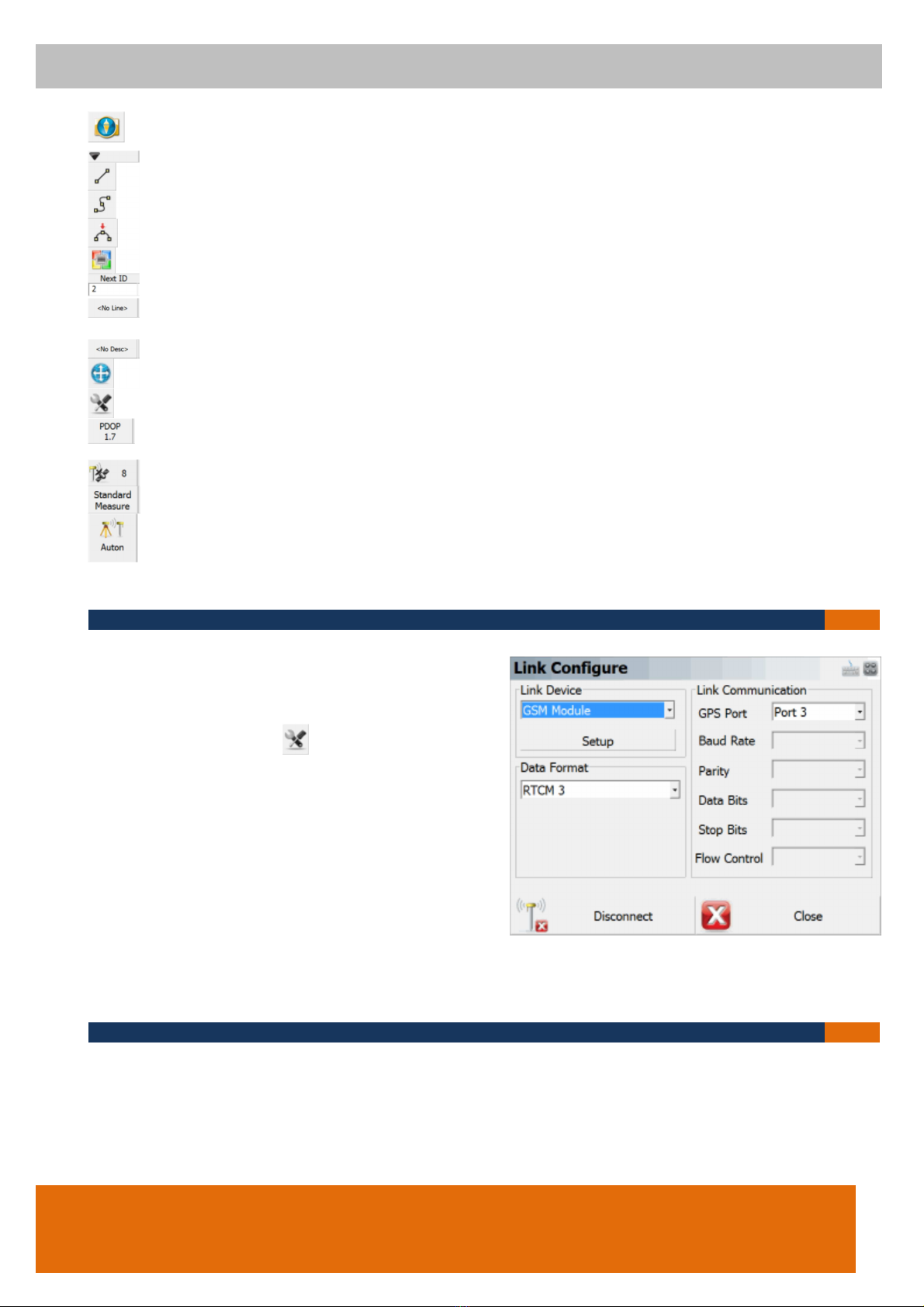
Nach Beendigung der kompletten Aufnahme der Punkte verbinden Sie die Antenne mit der mitgelieferten
Konfigurationssoftware um die einzelnen Dateien aus der Antenne auszulesen. Zusätzlich ermöglicht es
Ihnen die Software die Antennenhöhe und den Dateinamen vor dem Download zu verändern.
Über die geo-FENNEL-Postprocessing-Software können die einzelnen Datenpakete geöffnet und ausge-
wertet werden.
F
SICHERHEITSHINWEISE
WARN- UND SICHERHEITSHINWEISE
•Richten Sie sich nach den Anweisungen der Bedienungsanleitung.
•Anleitung vor Benutzung des Gerätes lesen.
•Niemals das Gehäuse öffnen. Reparaturen nur von autorisierten Fachhändlern durchführen las-
sen.
•Keine Sicherheits- und Warnhinweise entfernen.
•Diese Gebrauchsanleitung ist aufzubewahren und bei Weitergabe des Gerätes mitzugeben.
UMGANG UND PFLEGE
•Messinstrumente generell sorgsam behandeln.
•Nach Benutzung mit einem weichen Tuch reinigen (ggfs. Tuch etwas im Wasser tränken). Wenn
das Gerät feucht war sorgsam trocknen.
•Erst in den Koffer oder Tasche packen wenn es absolut trocken ist. Bitte darauf achten dass
auch der Koffer immer trocken ist bevor das Gerät hineingepackt wird.
•Transport nur im Originalbehälter oder –tasche.
UMSTÄNDE DIE DAS MESSERGEBNIS VERFÄLSCHEN ODER NICHT ERMÖGLICHEN
•Messungen innerhalb von Gebäuden oder in bewaldeten Gebieten sind nicht möglich da die Ab-
schattung zu den Satelliten zu groß ist.
•Bei Messungen innerhalb von Ortschaften oder Waldgrenzen ist darauf zu achten dass eine ge-
nügende Anzahl von Satelliten zur Verfügung steht die ein verwertbares Signal aussenden.
ELEKTROMAGNETISCHE VERTRÄGLICHKEIT
Es kann nicht generell ausgeschlossen werden dass das Gerät andere Geräte stört (z.B. Navigationsein
richtungen); durch andere Geräte gestört wird (z.B. elektromagnetische Strahlung bei erhöhter Feldstär
ke z.B. in der unmittelbaren Nähe von Industrieanlagen oder Rundfunksendern).
8

DE
CE-KONFORMITÄT
Das Gerät hat das CE-Zeichen gemäß den Normen EN 60950-1:2006+A11:2009
+A1:2010+A12:2011+A2:2013; EN 62479:2010; ETSI EN 301 489-1 V1.9.2 ETSI EN 301 489-3
V1.6.1 EN 55022: 2010 EN 55024: 2010; ETSI EN 300 440-1 V1.6.1 ETSI EN 300 440-2 V1.4.1
GARANTIE
Die Garantiezeit beträgt zwei (2) Jahre beginnend mit dem Verkaufsdatum. Die Garantie erstreckt sich
nur auf Mängel wie Material-oder Herstellungsfehler sowie die Nichterfüllung zugesicherter Eigenschaf-
ten. Ein Garantieanspruch besteht nur bei bestimmungsgemäßer Verwendung. Mechanischer Verschleiß
und äußerliche Zerstörung durch Gewaltanwendung und Sturz unterliegen nicht der Garantie. Der Ga-
rantieanspruch erlischt wenn das Gehäuse geöffnet wurde. Der Hersteller behält sich vor im Garantie-
fall die schadhaften Teile instand zusetzen bzw. das Gerät gegen ein gleiches oder ähnliches (mit glei-
chen technischen Daten) auszutauschen. Ebenso gilt das Auslaufen der Batterie nicht als Garantiefall.
HAFTUNGSAUSSCHLUSS
Der Benutzer dieses Produktes ist angehalten sich exakt an die Anweisungen der Bedienungsanleitung
zu halten. Alle Geräte sind vor der Auslieferung genauestens überprüft worden. Der Anwender sollte sich
trotzdem vor jeder Anwendung von der Genauigkeit des Gerätes überzeugen.
Der Hersteller und sein Vertreter haften nicht für fehlerhafte oder absichtlich falsche Verwendung sowie
daraus eventuell resultierende Folgeschäden und entgangenen Gewinn.
Der Hersteller und sein Vertreter haften nicht für Folgeschäden und entgangenen Gewinn durch Natur-
katastrophen wie z.B. Erdbeben Sturm Flut usw. sowie Feuer Unfall Eingriffe durch Dritte oder einer
Verwendung außerhalb der üblichen Einsatzbereiche.
Der Hersteller und sein Vertreter haften nicht für Schäden und entgangenen Gewinn durch geänderte
oder verlorene Daten Unterbrechung des Geschäftsbetriebes usw. die durch das Produkt oder die nicht
mögliche Verwendung des Produktes verursacht wurden.
Der Hersteller und sein Vertreter haften nicht für Schäden und entgangenen Gewinn resultierend aus ei-
ner nicht anleitungsgemäßen Bedienung.
Der Hersteller und sein Vertreter haften nicht für Schäden die durch unsachgemäße Verwendung oder
in Verbindung mit Produkten anderer Hersteller verursacht wurden.
9

EN
Dear Customer
Thank you for your confidence in us having purchased a geo-FENNEL instrument.
For the optimum performance of the instrument please read this manual carefully and keep it in a con-
venient place for future reference. This manual contains important safety information that should be
read and understood before use.
Technical specification and design are subject to change without notification.
geo-FENNEL
Precision by tradition.
Contents
1.
Standard equipment list
A
2. Features
B
3. Keypad layout
C
4. Power supply
D
5. Operation
E
6. Safety notes
F
A
SUPPLIED WITH – FGS 1 Complete-SET – Base + Rover co figuratio
•2 x GNSS-Antenna FGS 1
•4 x Li-Ion-Batteries for FGS 1
•2 x Charging Stations
•2 x Connection Cable USB
•2 x Connection Cable RS232
•1 x Adaptor for Tribrach
•1 x Clamp for Antenna Pole
•1 x Fieldcontroller with FieldGenius Software
•1 x Li-Ion-Battery for Fieldcontroller
•1 x USB-Connection Cable for Fieldcontroller
•Software
•User Manual
•Case
A
SUPPLIED WITH – FGS 1 with Field co troller – Network co figuratio
•1 x GNSS-Antenna FGS 1
•2 x Li-Ion-Batteries for FGS 1
•1 x Charging Station
10

EN
•1 x Connection Cable USB
•1 x Connection Cable RS232
•1 x Clamp for Antenna Pole
•1 x Fieldcontroller with FieldGenius Software
•1 x Li-Ion-Battery for Fieldcontroller
•1 x USB-Connection Cable for Fieldcontroller
•Software
•User Manual
•Case
SUPPLIED WITH – FGS 1 A te a si gle receiver (Base) co figuratio
A
•1 x GNSS-Antenna FGS 1
•2 x Li-ion-Batteries for FGS 1
•1x Charging Station
•1x Connection Cable USB
•1x Connection Cable RS232
•Software
•User Manual
•Case
FEATURES
B
6. Keypad
7. Plug-in for Connection Cable
8. 5/8“-Thread
9. Battery Door
10. Plug-in for Whip Antenna
11

EN
C
KEYPAD LAYOUT
A zeige
Status
Bedeutu g
1.
Differential LED
Flashs once per second
r
eceiv
ing
/transmitting differential data
2.
Satellite LED
Extinguishing or flashing once
per 5 seconds
Searching satellites
Flashs N times per 5 seconds
Receiving N satellites
3.
Bluetooth® LED
Flashing
Other
devices connected to the ante
n-
na
4.
Battery LED
Illuminated
Enough power
Flashing
Low battery
5.
Data Logging LED
Press long and hold
to switch on/off raw data logging.
Flash depends on
sampling
6.
Power button
Press
and hold
the key to
switch the
antenna on/off.
D
POWER SUPPLY
INSERT BATTERY
Open the battery compartment cover and insert the two Li-Ion-batteries. Close the cover and ensure
that the compartment is closed completely.
As soon as the first battery will be empty the battery LED of the second battery will be illuminated and
the unit starts using the second battery. Meanwhile you can remove the empty one to charge it. The
LED of the charging station changes the color from red to blue if the battery is fully charged. The charg
ing time is 6 to 7 hours.
12

EN
OPERATION
E
Set up the base antenna over a known or unknown point and switch it on. Mount the rover antenna on
top of the antenna pole and fix the clamp for the controller on it as well. The fieldcontroller will be
mounted to the clamp. Start the controller and open the FieldGenius software.
First Steps
After starting the software for the first time you will be prompted to register the software. The shown
serial number is unique for this device.
To use the software with all fucntions you have to reg-
ister it. Open the website
www.microsurvey.com/register andyou will automati-
cally get to the register screen Follow up the instruc-
tions. Enter the given key code in the FieldGenius
screen to finalize the registration. If you don’t register
the software you can only use it in the demo mode.
In the demo mode you can measure only 30 points per
job. All further applications can be used in full.
As a second step you can create a new project open an existing job or delete a project.
After Selecting a “New Project“ you have to enter in a job name in the mask. In the lower grey window
the current settings will be shown. Before confirming the new project with the OK button you can select
the settings for measuring units and coordinate system.
13

EN
After the settings have been carried out you can confirm the new project with the OK button. In the
next window you choose the GPS Antenna set up the base station and you can connect the rover an-
tenna by Bluetooth® or serial cable connection with the software as well. When the connection has
been completed the main menu will start automcaically.
Extend the toolbar display from to
Returns to the standard display
Displays the coordinates of the current position of your rover.
Zoom
-
f
rame
:
zoom
s
in till all points are shown in the screen.
Dynamic
z
oom
:
w
hen enabled drag on the map screen to define a zoom
window
.
Zoom
w
indow
:
the screen
inside the box will be enlarged
Dynamic
p
lan
:
you can drag across your map screen to pan
around your project.
Zoom
p
revious
:
y
ou can use this to zoom back up to 10 previous views.
H
ide
s
unrelated points and lines in your map during stakeout
3D
v
iew
:
opens the 3D toolbar.
Layer
m
anager
:
opens the
l
ayers
m
anager for managing
visibility of layers in your database
Surface
m
anager
:
opens the surface manager
.
Options
Help
14

EN
Main
m
enu
b
utton
:
press the button to enter
into the main m
e
nu
Mini
t
oolbar
b
utt
o
n
:
opens the mini toolbar.
Draw
l
ines
b
utton
.
Draw
c
urvy
l
ines
b
utton
.
Draw 3
-
p
oint
a
rc
b
utton
.
User
d
efined
b
utton
.
Next ID
F
ield
.
Active
l
ine
l
ist
b
utton
.
Description
s
election
b
utton
Auto
-
Center
:
re
-
center the display on the current position of your
receiver.
GPS
s
ettings
DOP
v
alues
:
displays the current
DOP (
d
ilution of
p
recision) values.
Satellite
p
lot/ Satellite
l
ist
.
GNSS
m
easurement
m
odes
m
enu
.
Measure
:
measure
s
and displays if the signal is auton
omous float or fixed.
C
ORS
Measureme t
In order to get correction data from a network you
need to have an own user log in from a provider.
Connect the rover with FieldGenius and start a meas-
urement application. With the button you enter
the settings menu. Use Link Configuration Setup to
type in your user data.
Enter your personal log-in and press the CONNECT
button to start the connection with the network. De-
pending on the provider service you can choose dif-
ferent Mountpoints or it shows the last one which you
used as a shortcut.
Static Measureme t
For static measurements it is not necessary to use a field-controller. Set up the tripod over a unknown
(new) point and mount the antenna on a tribrach adaptor. Level the bubbles and check - by using the
optical or laser plummet - if the antenna is set up exactly over your measuring point. Don’t forget to
note down the height from the index mark to the measuring point.
15

EN
In order to measure a vector between a known and unknown point you need to collect raw data simul-
taneously in accordance with the length and the geometry of your measuring condition. A “thumb rule”
is to set the occupation time to 10 minutes for a vector up to 10 km and add 1 minute more for every
additional kilometer. The raw data will be stored in the internal memory in accordance with the receiver
setting that have a predefined with the receiver configuration tool (you can set the sampling interval el-
evation mask etc.).
Switch on the antenna and after warm up activate the data logging button to start the data recording.
Stop the recording by pressing the data logging button again. To record further measuring points don’t
switch off the antenna otherwise you risk a cold start which takes more time than a warm start.
After finishing the complete recording of your measuring points connect the antenna with the supplied
configuration software to download the files from the internal memory. Before downloading change the
file name and the height of the antenna by right click on the file.
Use the geo-FENNEL post processing software to open the different measurement files for further pro-
cessing. You can also use external reference data by importing RINEX files it possible.
F
SAFETY NOTES
SAFETY INSTRUCTIONS
•Follow up the instructions given in the user manual.
•Use the instrument for measuring jobs only.
•Do not open the instrument housing. Repairs should be carried out by authorized workshops on-
ly. Please contact your local dealer.
•Do not remove warning labels or safety instructions.
•Keep the instrument away from children.
•The user manual must always be kept with the instrument.
CARE AND CLEANING
Handle measuring instruments with care. Clean with soft cloth only after any use. If necessary damp
the cloth with some water. If the instrument is wet clean and dry it carefully. Pack it up only if it is per-
fectly dry. Transport in original container / case only.
SPECIFIC REASONS FOR ERRONEOUS MEASURING RESULTS
•It is not possible to measure inside of buildings and forest areas due to the shading of the satel-
lites when taking.
•Measurements inside of urban areas or treelines take care that enough satellite signals can be
received.
16

EN
ELECTROMAGNETIC ACCEPTABILITY (EMC)
It cannot be completely excluded that this instrument will disturb other instruments (e.g. navigation
systems); will be disturbed by other instruments (e.g. intensive electromagnetic radiation nearby in
dustrial facilities or radio transmitters).
CE-CONFORMITY
The instrument has the CE-mark according to EN 60950-1:2006+A11:2009
+A1:2010+A12:2011+A2:2013; EN 62479:2010; ETSI EN 301 489-1 V1.9.2 ETSI EN 301 489-3 V1.6.1
EN 55022: 2010 EN 55024: 2010; ETSI EN 300 440-1 V1.6.1 ETSI EN 300 440-2 V1.4.1
WARRANTY
This product is warranted by the manufacturer to the original purchaser to be free from defects in ma
terial and workmanship under normal use for a period of two (2) years from the date of purchase. Dur
ing the warranty period and upon proof of purchase the product will be repaired or replaced (with the
same or similar model at manufacturers option) without charge for either parts or labour. In case of a
defect please contact the dealer where you originally purchased this product. The warranty will not
apply to this product if it has been misused abused or altered. Without limiting the foregoing leakage
of the battery bending or dropping the unit are presumed to be defects resulting from misuse or
abuse.
EXCEPTIONS FROM RESPONSIBILITY
The user of this product is expected to follow the instructions given in the user manual. Although all
instruments left our warehouse in perfect condition and adjustment the user is expected to carry out
periodic checks of the product’s accuracy and general performance.
The manufacturer or its representatives assumes no responsibility of results of a faulty or intentional
usage or misuse including any direct indirect consequential damage and loss of profits.
The manufacturer or its representatives assumes no responsibility for consequential damage and loss
of profits by any disaster (earthquake storm flood etc.) fire accident or an act of a third party
and/or a usage in other than usual conditions.
The manufacturer or its representatives assumes no responsibility for any damage and loss of profits
due to a change of data loss of data and interruption of business etc. caused by using the product or
an unusable product.
The manufacturer or its representatives assumes no responsibility for any damage and loss of profits
caused by usage other than explained in the user manual.
The manufacturer or its representatives assumes no responsibility for damage caused by wrong
movement or action due to connecting with other products.
SAFETY INSTRUCTIONS
Follow up the instructions given in the user manual.
Do not stare into the beam. The laser beam can lead to eye injury. A direct look into the beam (even
from greater distance) can cause damage to your eyes.
Do not aim the laser beam at persons or animals.
The laser plane should be set up above the eye level of persons.
Use the instrument for measuring jobs only.
17

EN
Do not open the instrument housing. Repairs should be carried out by authorized workshops only.
Please contact your local dealer.
Do not remove warning labels or safety instructions.
Keep the instrument away from children.
Do not use the instrument in explosive environment.
The user manual must always be kept with the instrument.
18

EN
Technical Specifications
Signal Tracking
256 channels with simultaneously tracked
satellite signals
- GPS: L1 C/A, L1/L2P, L5
- BeiDou: B1, B2, B3
- GLONASS: L1/L2
- SBAS: WASS, EGNOS, MASAS
Performance Specifications
Cold start: <50s
Warm start: <30s
Initialization time: typically < 10s
Initialization reliability: typically > 99.9%
Signal reacquisition: <2s
Positioning Specifications
Post Processing Static
- Horizontal: 2.5 mm + 1 ppm RMS
- Vertical: 5 mm + 1 ppm RMS
Real Time Kinematic
- Horizontal: 10 mm + 0.5 ppm RMS
- Vertical: 20 mm + 0.5 ppm RMS
E-RTK (<100km)
1
- Horizontal: 0.2 m + 1 ppm RMS
- Vertical: 0.4 m + 1 ppm RMS
Code differential GNSS positioning
- Horizontal: 0.25 m+ 1 ppm RMS
- Vertical: 0.5 m + 1 ppm RMS
SBAS: Typically < 1 m 3D RMS
Standalone: <1.5 m RMS
Communications
1 Serial port (7 Pin Lemo),
Baud rates up to 921 600 bps
Radio moderm, Tx/Rx with full frequency range from
410-470
2
Mhz
-Transmit power : 0.5-2W adjustable
- range : 1-4km
Positioning data outputs, 1HZ, 2HZ, 5HZ, 10HZ
5 LED Indicating light (indicating Power, Satellite
Tracking, Differential Data and Data Recording)
Bluetooth®; V 2.X protocol, work compatible with Windows
7, Windows mobile and Android .
Data Format
Data inputs/outputs
-Correction data I/O: RTCM 2.x, 3.x,CMR(GPS only),
CMR+(GPS only)
Position data outputs:
- ASCII: NMEA-0183 GSV, RMC, HDT, VHD, GGA, GSA,
ZDA, VTG, GST, PJK, PTNL
Geo fennel Binary update to 20Hz
Physical
Size (W×H): 15.8cm×7.5cm
Weight: 0.95kg(include battery)
Environmental
Operating temperature: -40 °C to +65 °C (-40°F to 149°F)
Storage temperature: -40 °C to +85°C (-40°F to 185°F)
Humidity: 100% condensation
Waterproof and dust proof: IP67 - protected from temporary
immersion to depth of 1 meter, floats
Shock: survives a 2-meter drop on to concrete
Electrical
Input Voltage: 5-27 VDC
Power consumption: 2.85 W(3 constelations)
Li-ion battery capacity: 2×1800 mAh ,
Up to 8 hours typcially.
Memory: 256 MB internal
Software
MicroSurvey Field Genius
1
E-RTK, Beidou B3 signal used in RTK calculate engine ; concern the current situation, this mode can be used in APAC.
2
410-470Mhz, 3 frequency range, 410-430,430-450,450-470
19

geo
-
FENNEL GmbH
Kupferstr. 6
D-34225 Baunatal
Tel. +49 561 / 49 21 45
Fax +49 561 / 49 72 34
info@geo-fennel.de
www.geo-fennel.de
Tech ische Ä deru ge vorbehalte .
All i strume ts subjected to tech ical cha ges.
04/2014
Precisio by traditio .
Table of contents
Languages:
Other geo-FENNEL Receiver manuals