Geonor T-200B-M User manual

Rev: 10.7
1
GEONOR
T-200B SERIES PRECIPITATION GAUGE
MANUAL FOR
600-mm, 1000-mm & 1500-mm capacity options

Rev: 10.7
2
TABLE OF CONTENTS
1. INTRODUCTION – PRECIPITATION GAUGE
................ 3
1.1. Principle of Operation ................................................................ 3
1.2. Why is it used............................................................................. 3
1.3. Advantages................................................................................ 3
2. INSTALLATION
....................................................................... 4
2.1. Foundation considerations......................................................... 4
2.2. Plan height of collection inlet...................................................... 4
2.3. Locate gauge away from structures and objects........................ 4
2.4. Pedestal installation ................................................................... 5
2.5. Precipitation gauge installation .................................................. 6
2.6. Electrical hookup........................................................................ 7
2.7. Antifreeze - as needed............................................................... 8
2.8. Hydraulic Oil to Eliminate Evaporation....................................... 9
2.9. Loosen Setscrew on transducer................................................. 9
2.10. Replace gauge cover ............................................................... 9
2.11. Install Alter Wind Screen (see Section 4)................................ 10
2.12. Hook up data logger and begin readings ................................. 10
3. REFERENCES
......................................................................... 11
4. MOUNTING INSTRUCTIONS FOR WIND SHIELD
........ 12-17
5. MAINTENANCE
....................................................................... 18
5.1. Tools needed ............................................................................. 18
5.2. Service interval .......................................................................... 18
5.3. Servicing .................................................................................... 18
5.4. Check function of transducer ..................................................... 19
5.5. Removing and replacing transducer .......................................... 20
5.6. Rust protection maintenance ..................................................... 20
6. DRAWINGS / DIAGRAMS / FIGUERS
………………………….
20
6.1. Gauge – vertical cross section – shows parts............................ 21
6.2. Connection of TH501 Interface & transient arrestor................... 22
6.3. Concrete foundation block ......................................................... 23
6.4. Gauge with 1-m pedestal and Alter windscreen......................... 24

Rev: 10.7
3
1. INTRODUCTION - PRECIPITATION GAUGE
1.1. Principle of Operation
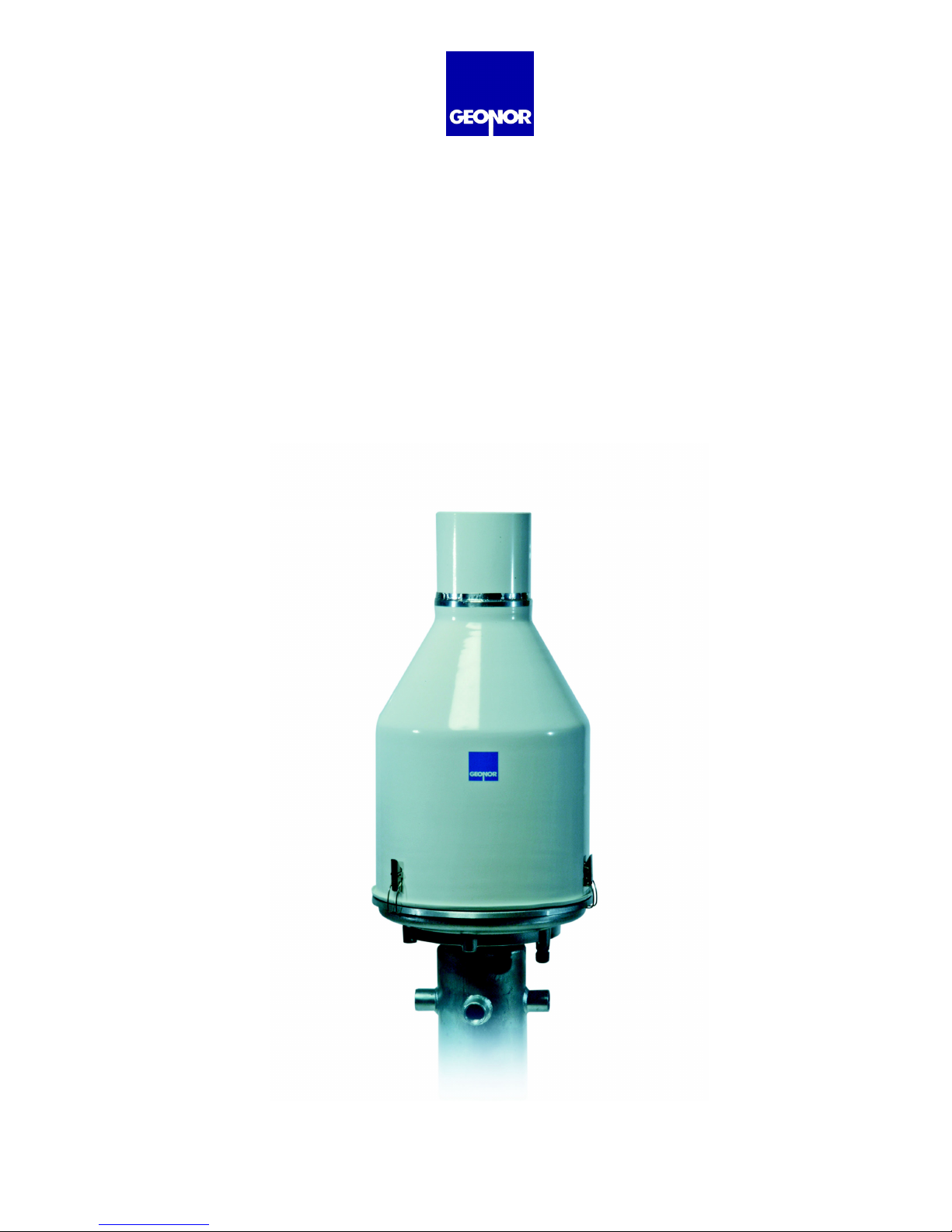
The T-200B Series Precipitation Gauges are weighing bucket precipitation
gauges. They are available in 600-mm, 1000-mm and 1500-mm capacity
versions. It uses a precision vibrating wire (VW) transducer to weight and
determine the precipitation collected. The collection container in the T-200B
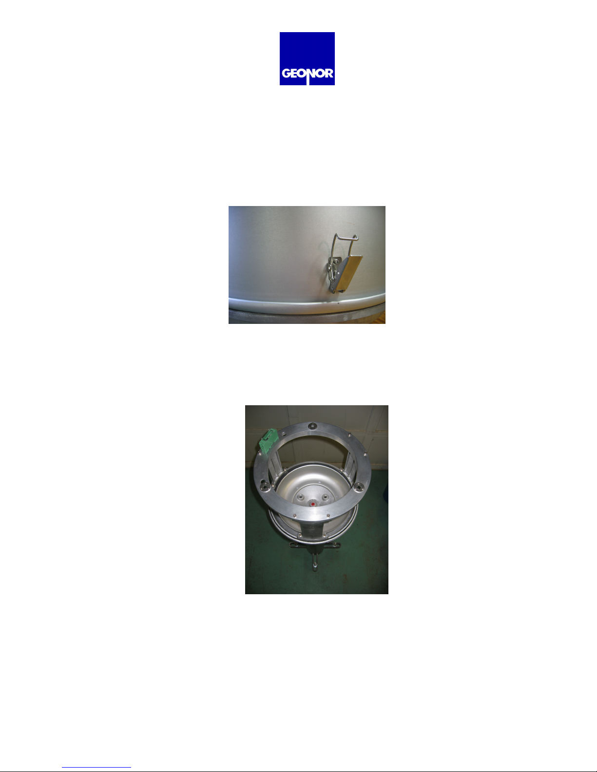
Series gauge is suspended from three points, each supporting 1/3 of the weight.
With this type of set-up there are options available to measure precipitation with
up to triple redundancy. With equal load distribution, 1, 2 or 3 VW transducers,
form now on referred to as sensors, can be used to measure total precipitation
and rate of precipitation. The use of extra sensors provides backup and
redundancy in case one transducer stops recording. As long as 1 of the sensors
is recording the precipitation rate and total will be recorded. With proper care
sensors have been shown to record for more than 27 years without failing.
The Sensor was developed in the 1960’s at GEONOR’s then parent research
foundation, The Norwegian Geotechnical Institute (NGI.) Bakkehøi
1
, et al (1985).
NGI used the Sensor in the T-200B gauge to measure rain and snow
precipitation. NGI developed the gauge due to the need for automatically
recording precipitation for avalanche research.
1.2. Why it is used
Since its introduction in 1985, based on the results of extensive tests by the
World Meteorological Organization (WMO) it was adopted by several
Scandinavian meteorological services. Starting in the late 90’s U.S. and
Canadian agencies have tested the gauge extensively with good results.
Consequently it has seen increasing use in North America.
1.3. Benefits of using Vibrating Wire Transducers
The Sensor has certain advantages over other types of load transducers and
counting systems used in precipitation gauges:
(1) Sensitivity better than 0.1 mm.
(2) It has little temperature sensitivity.
(3) It has no moving parts.
(4) Very low power consumption.
(5) The pulse signal can be transmit by cable over 1 km.
(6) Data Acquisition Systems can easily log the 0 to 5 V signal with the TH-501
Interface.
(7)
Exceptional Long-term drift free performance – measured by a 27-year test at
NGI.
1
See References – Section 3.

Rev: 10.7
4
2. INSTALLATION
IMPORTANT: A solid foundation and rigid pedestal are needed for proper gauge performance.
2.1. Foundation considerations in soil, on rock, or on a structure
Regardless of whether the pedestal is installed in soil, on rock or on a structure,
the pedestal must be rigid enough to prevent movements and vibrations due to
wind, frost heave, loosening of soil, etc.
2.2. Plan height of collection orifice above anticipated snow depth
With the foundation flush with ground, and using the 1-m pedestal the inlet on the;
T-200B (600-mm capacity) will be approximately 1.75-m above ground.
T-200B-M (1000-mm capacity) will be approximately 1.75-m above ground.
T-200B-MD (1500-mm capacity) will be approximately 2.05-m above ground
It is recommended to install the gauge so the inlet is at least 50 cm (20 inch)
above the anticipated snow depth. For deeper snow a 2.5 m pedestal is available
or the concrete foundation can be raised.
2.3. Locate gauge away from structures and objects
For best results, locate the gauge where the wind is least affected by structures.
i.e. buildings, cliffs, and trees, etc. A minimum of 45°from the top of the inlet to
open sky should be observed.
2.3.1. Attaching the pedestal to a foundation.
The pedestal will be attached to the foundation with 4 anchor bolts. The
bolts should be oriented in a North – South & East – West cross (see Fig
7.6). Make sure bolts are set vertically. A wood template can be helpful in
positioning the anchor bolts. (see Fig. 7.6)
2.3.1.1. Anchor bolt size, length & material
⅞”, ¾” or 20-mm – Ø galvanized or stainless steel threaded anchor
bolts at a minimum length of 375 mm (15 inch). Make sure to leave
at least 150 mm (6 inch) of exposed thread above foundation
surface.

Rev: 10.7
5
2.3.2. Using a Concrete foundation
The concrete foundation block (Fig. 7.6.) must remain steady. As a
general guideline, see dimensions in (Fig. 7.6). The size and depth
depends mostly on frost depth and the strength of the soil. Other factors
may come into play at different location. Movement of the gauge may lead
to errors in the data.
2.3.2.1. Excavation depth
Excavate deep enough to avoid movement from frost heave or
dynamic forces caused by wind, etc. As a general guideline
excavate 600 to 1000 mm (24 to 40 inch) deep.
2.3.2.2. Size of concrete block foundation
The height of the block can extend from flush with the ground to any
required height depending location. A typical concrete foundation
block width is 600 mm (24 inch) square.
2.3.3. Using a Rock foundation
On a competent rock surface, drill holes for anchor bolts (see sec 2.3.1.).
Grout the anchor bolts in place at minimum depth of 200 mm. Make sure
there is sufficient thread to mount the pedestal and clamping nuts, at least
150 mm (6 inch) (see Fig. 7.7.).
2.4. Pedestal Installation
IMPORTANT: A rigid pedestal is required for accurate data. If there is movement
of the gauge your data may be affect.
2.4.1. Pedestal details
We recommend the T-200B gauge be mounted on a GEONOR pedestal.
GEONOR provides galvanized steel pedestals in 1 m and 2.5 m heights.
2.4.2. Installing pedestal
Mount the reaction nut, lock washer and washer on anchor bolt approx 1”
above the surface
(see Fig 7.7)
. Do not let pedestal rest on base.
Using the level, adjust the 4 nuts so they are level. When
mounting
pedestal be sure the mounting holes for the gauge form a triangle pointing
south
(See photo 2-2)
. Level gauge and install upper washers, lock washers,
and nuts on anchor bolts. Tighten and check that the pedestal is rigid and
level. Make adjustments if necessary.

Rev: 10.7
6
2.5. Precipitation Gauge installation
2.5.1. Remove gauge cover
To remove the cover, release the 3 clamps around the base and lift it
straight up to clear the frame.
NOTE: Press hook into locking lugs to keep them from catching on base. (See photo 2-1)
(Photo 2-1)
2.5.3. Placing gauge on pedestal
Align support holes in the base of gauge with mounting holes on top of
pedestal (
See photo 2-2)
. This places 1 Sensor at the northern point.
(Photo 2-2 Gauge frame on Pedestal)

Rev: 10.7
7
2.5.4. Insert mounting bolts
Insert the 3 M8x1 bolts through the black washers into the support holes in
the base and screw into pedestal. Do not tighten bolts leave space to
adjust level orientation of gauge. Level the gauge by using the level
supplied and adjusting the leveling screw located under the gauge. When
the gauge is level tighten the 3 mounting bolts.
2.5.5. Install transducer/s & support chains
IMPORTANT: The Sensor has a setscrew on the side which helps protect it. The
screw must be loosened or removed for the sensor to work.
If using 1 sensor, install it at the northern support point. Install support
chains in the other 2 support points. If this is a 3-sensor unit, install
sensors and make notes of each location. Make sure the wires from
sensor are on the same side as the hole in the rim.
Connect S-hooks at bottom of sensors and chains to support dish through
predrilled holes. Place level across support dish. By turning the black
knurl nuts on the sensors and chains fine-tune the level of the support
dish.
2.5.6. Install container in support dish
Carefully place the container in the support dish making sure it sits snug.
Align mark on bucket (black dot) with the location of similar mark at one of
the support points. This is to ensure similar installation when the container
is removed and replaced. Check level by placing the level on the container
and adjusting the black knurl nuts again.
2.6. Electrical hookup
2.6.1. Connect Sensor to Transient Arrestor (TA) on rim
Line up wire coming from top of the sensor with opening in support rim so
wire comes straight up through the rim. Do not bend wire in more than 3-
cm radii. Connect wire to green transient arrestor box on the support rim,
red (+) to terminal 6, and black (-) to terminal 4. Use wire clips or cable
ties to keep in place.

Rev: 10.7
8
IMPORTANT: Leave a 1-2” bend radius on the sensor wire. Wires clamped to
the changesrim without this “loop” can cause changes in readings.
(Photo 2-3 - wire from sensor)
2.6.2. Connect wires from Transient Arrestor to Interface (TH501)
The wires should be properly shielded and be suitable for the environment
to which it will be exposed. Geonor can supply any length cable required.
Pass cable through strain-relief connector supplied through the base of the
gauge. Strip wires to appropriate length if using a multi-pair cable. Run
wires up support through opening in rim to Transient Arrestor. Connect (+)
to terminal 5 and (-) to terminal 3. (See Fig. 7.2.) Repeat for each Sensor.
Remove slack and tighten strain-relief connector. The transmission
distance between gauge and data collection terminal can be up to 1 km.
(3000 ft).
2.6.3. Over voltage protection – ground
If you are using a data logger it is suggested grounding the shielding at the
data logger, not at the Transient Arrestor. Do not ground at both ends.
2.7. Add antifreeze as needed
When the gauge is operating below 0°C, an antifreeze blend must be added to
keep collected precipitation in a liquid state. If the precipitation freezes the
sublimation may occur and eventually the container may break.
It is important to notice that the capacity of the collected precipitation is
decreased when antifreeze is added. The antifreeze becomes a part of the total
volume collected. A blend of Propylene glycol
2
and Methanol
2
(40/60) is used by
The US Climate Reference Network (USCRN). This blend is used to make the
antifreeze and H
2
O similar in density preventing stratification. Stratification will
lead to the formation of ice. Tables in the following sections show the amount of
Propylene glycol needed to keep the collected precipitation from freezing at
various temperatures. Other antifreeze solutions have been used successfully.
2
Check with local regulations regarding disposal.

Rev: 10.7
9
2.7.1. Antifreeze quantities required for below freezing temperatures
T-200B - 600 mm gauge collection container max capacity of 12 liters.
T-200B-M -1000 mm gauge collection container max capacity of 20 liters.
T-200B-MD - 1500 mm gauge collection container max capacity of 30 liters.
Antifreeze Solution
Propylene Glycol (40%) / Methanol (60%)
Antifreeze as % of total capacity Freezing Point (°F) Freezing Point (°C)
0 32 0
10 26 -3
20 20 -7
30 10 -12
36 0 -18
40 -5 -20
43 -10 -23
48 -20 -29
52 -30 -34
55 -40 -40
58 -50 -46
60 -60 -51
2.8. Add thin layer of Oil to Eliminate Evaporation
To eliminate evaporation it is essential to use oil in both winter and
summer. Add 0.4 liters oil. We recommend the Low Pour Hydraulic Oil. Other
oils have been used. It must not become viscous in the temperature ranges
anticipated. It is recommended to change the oil at least once a year to avoid
deterioration, which can result in evaporation of collected precipitation.
2.9. Loosen Setscrew on transducer
*If you have not already installed sensor and support chains, go to
section 2.5.5 before continuing.
Unscrew the setscrew at least 4 revolutions to keep it clear of the vibrating wire.
It can be removed completely or left in place after loosening. If left in place, wrap
the electrical that came with the sensor around the sensor and setscrew again to
keep it in place.
We recommend keeping the setscrew tight until maintenance has been completed.
2.10. Replace gauge cover
Replace gauge cover and snap the 3 clips in place.
NOTE: The clips fasten to sections of the base with a lip. Look or feel for theses sections.

Rev: 10.7
10
2.11. Install Alter Type Wind Screen (see section 4, p.13)
To prevent undesirable effects of wind turbulence around the gauge, a Wind
Screen should be installed.
The GEONOR pedestal has Wind Screen mounts on the pedestal. Using the
Geonor Alter Wind Screen assures a proper installation at the specified, 13-mm
height above the top of the gauge orifice. (See Section 4, p. 13)
Install the Alter windscreen so the blades are approximately 13-mm above the top
of the T-200B inlet.
2.12. Connect data logger or manual read-out unit and begin readings
The Sensor is audible when power is supplied. Each transducer is slightly
different but the approximate range is from 1000 Hz when empty to 3000 Hz with
a full container.
To calculate the amount of precipitation in cm from the frequency, use the
following formula.
Each sensor comes with it’s own calibration sheet specific for that sensor.
P = A (f – f
0
) + B (f – f
0
)²
Where:
P= precipitation (in cm)
f = frequency reading (Hz)
A = Calibration constant, given
B = Calibration constant, given
f
0
= frequency with empty bucket at calibration (Hz), given

Rev: 10.7
11
3. REFERENCES
Bakkehøi, Steinar; Kjell Øien and E. J. Førland (1985) An Automatic Precipitation
Gauge based on Vibrating-Wire Strain Gauges, Nordic Hydrology No. 16, pp.
193-202
Tunbridge, Lloyd and Kjell Øien (1988) The advantage of Vibrating Wire
Instruments in Geomechanics, 2
nd
Intl. Symposium on Field Measurements in
Geomechanics, Balkema, Rotterdam, ISBN 90 6191 7786. Also publ. In
Norwegian Geotechnical Institute (NGI) internal report 55100-7 April 1987.

Rev: 10.7
12
ALTER WINDSCREEN PARTS
1. Blades (qty 32)
2. Spacers (qty 24)
3. Ring segments (qty 4)
4. Ring segment connectors (qty 4)
5. Connectors and caps for Ring Segments (qty 4)
6. Kee-Klamps (qty 4)
7. 1” galvanized pipe, thread is necessary on one end (qty 4)*
8. 1” galvanized pipe, thread is not necessary (qty 4)*

Rev: 10.7
13
4. INSTRUCTIONS FOR ALTER WINDSCREEN
1. Mark 500-mm from the threaded end on the horizontal pipes for Inner
Alter.
2.
Mount connectors for ring segment on vertical sections of pipe. Mark 817-
mm below the connector by wrapping tape around the pipe several times.
This marks the level of the Kee-Klamp.
(See photo 4-1)
. Connectors for outer
Alter can be mounted at a later time.

Rev: 10.7
14
3. Insert horizontal tubes into the threaded fittings on the pedestal.
Tighten with pipe wrench.
4. Slide the Kee-Klamps on so the inside edge lines up with the 500-mm.
5. Align the clamps vertically and tighten nut with Allen key supplied.
Adjustments will to be made later.

Rev: 10.7
15
6. Insert vertical pipes for Inner Alter in Kee-Klamp with connector for
ring at top. The tape will rests on the Kee-Klamp.
7. Lay ring segments of inner Alter down and attach a ring connector to
end of each segment. Slide the blades and spacers on in order
shown below. Keep the channels of the blades facing outward.
Connect the segments to complete a full circle.
(Note: The ring connectors and the ring slot “A” act as spacers.)
8. Place the ring in the slots on the vertical pipes.
(Note: Blades not shown)

Rev: 10.7
16
9. Install caps to hold ring firmly in place.
10. Make adjustments.

Rev: 10.7
17
5. MAINTENANCE
5.1. Tools needed
•Screw driver, 4-mm blade
•Hammer
•Adjustable spanner (wrench) 0-27 mm
•Container for disposal of anti-freeze mixture (12 liter minimum)
•Funnel
•Measuring cylinder, 1 liter
•Siphon
•Level
5.2. Service interval
Service the gauge when the container needs to be emptied. Inspection is
recommended 2 times a year.
Automatic emptying systems have been used. Please contact us for more information.
5.3. Servicing
Disengage the 3 spring fasteners holding gauge cover to the base and remove
the housing (see Section 2.5.1.). Tighten the setscrew of the Sensor to avoid
damaging the vibrating wire.
Antifreeze mixtures are toxic. Do not attempt to suck on tube to start flow.
NOTE: If the oil in the container does not need to be replaced there is no
need to remove it.
Use the siphon pump supplied or something similar to remove liquid from
container or remove manually. Remember a full container is very heavy.
Using the siphon pump supplied, place the shorter end at the bottom of the
bucket. Holding the receptacle at a lower level than the bucket pump the siphon
until flow starts. Once the flow has started there is no need to pump. Simply wait
until you have removed the proper amount.
You can empty the bucket by hand. Be careful not to overload the VW load cell
or subject it to any shock.
Clean bucket and add required anti-freeze mixture and oil. Replace carefully in
the weighing dish aligning the black dot on the rim of the bucket with the one on
the support rim.

Rev: 10.7
18
***Loosen the setscrew on transducer***
Replace the gauge cover and lock 3 clamps.
5.4. Checking the function of the transducer
Empty bucket check
Level the bucket accurately (see Sections 2.5.4 & 2.5.6.). Check the
frequency with an empty bucket (f
o
-value) using a datalogger or a
GEONOR P-520N portable frequency counter
3
. Compare with the f
0
-value
on the calibration certificate for the transducer. If the difference is equal or
less than 10 Hz no adjustment is necessary. If the difference exceeds10
Hz a new value for constant A should be calculated. Use the new f
0
and
the new Ain your calculations.
Formula for calculating a new constant A with new f
o
A' = A + 2B(f
0
' – f
0
)
Where
A'
and
f
0
' are new values, and
A
,
B
and
f
0
are the original
calibration values. (See Section 2.13. or calibration sheet)
Check with precipitation in the bucket
Fill the container with 1-kg of water. If the water is free of air this equals a
volume of 1 liter. (Water from the tap can contain considerable air, which
must be taken into account. Boiling for 10 minutes can remove most of the
air.) 1 kg (1 liter) of water represents exactly 50 mm of precipitation.
Recalibrate the Sensor if it differs by more than 0.5% from the value on the
calibration sheet.
5.5. Removing and replacing transducer
•Remove gauge cover
•Tighten setscrew on VW load cell
•Lift out container carefully
•Disconnect electrical leads from the transient arrestor
•Unhook the S-hook from the support dish
•Hold the Sensor and remove knurled nut from top of adjustment screw
•Remove the Sensor from square guide in the support rim.
3
GEONOR model P-520M portable frequency counter.

Rev: 10.7
19
Install a new Sensor in the reverse order (see Section 2.5.5.)
IMPORTANT: The support dish must be free to swing in all directions without
noticeable resistance. Resistance in the support links can contribute to error
especially with low weights in the container.
When installing a new or recalibrated Sensor, use the new values for A, B and f
0
.
These are given on the calibration sheet with the Sensor.
5.6. Rust protection maintenance
For added protection, apply two layers of a rust preventing coating such as paint,
zinc-galvanizing spray or similar on all threaded parts of the pedestal and Wind
Screen.

Rev: 10.7
20
6. DRAWINGS / DIAGRAMS / FIGURES
6.1. T-200B Gauge – vertical cross section – shows parts ......... 21
6.2. Connection of TH501 Interface & transient arrestor ............. 22
6.3. Alter-shield details................................................................... 23
6.4. Concrete foundation block...................................................... 24
6.5. Gauge with 1m pedestal and Alter Windscreen .................... 25
This manual suits for next models
2
Table of contents