5
Recommended installation height HV50 arm: 2500
mm
Procedure:
1. The wall bracket is firmly attached to the wall by
means of 4 off 10 mm bolts. (When using the exten-
sion arm, please fix this bracket first – refer to item
2.1)
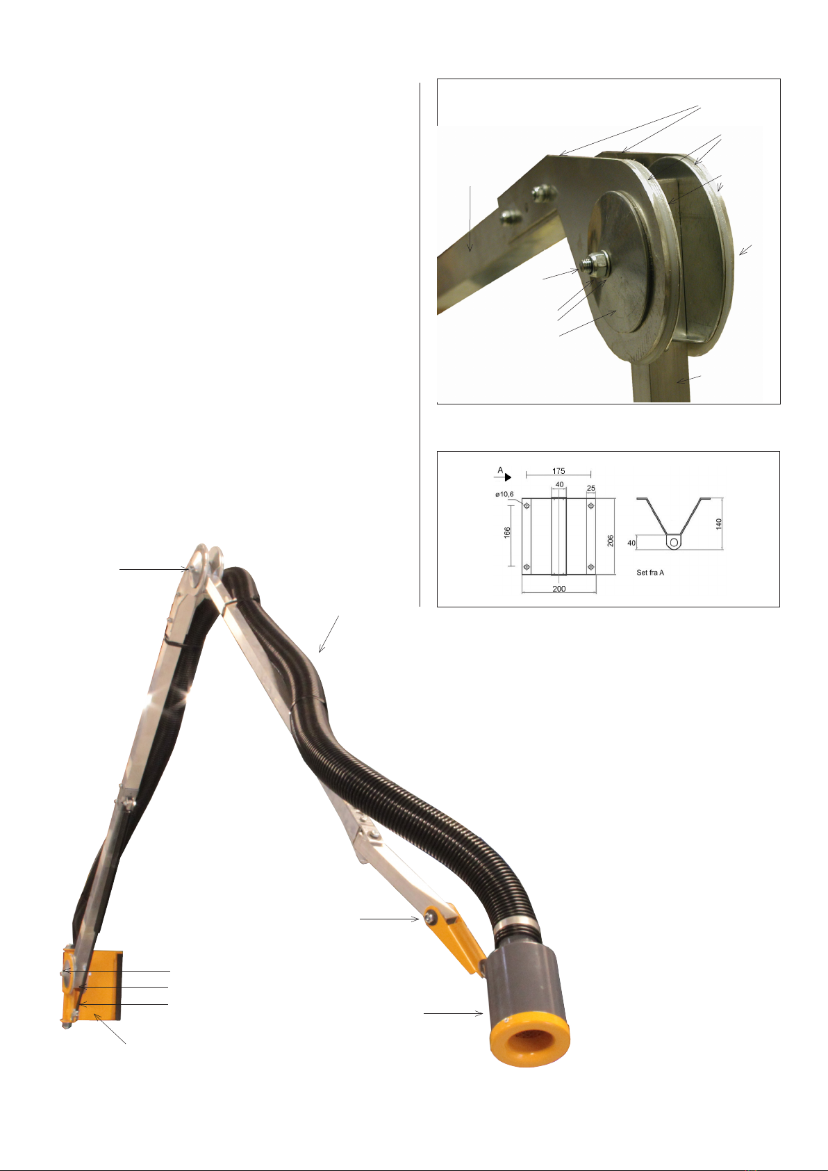
2. Mount the Arm on the wall bracket with the M16
bolt and friction discs. Make sure to fasten it in such
way that the Arm is easily rotated. If the inner joint/
arm hasn’t the wanted friction, the bell washer can
be loosen or tighten, or by adjusting the spring re-
tainer (against the wall to tighten – away from the
wall to loosen).
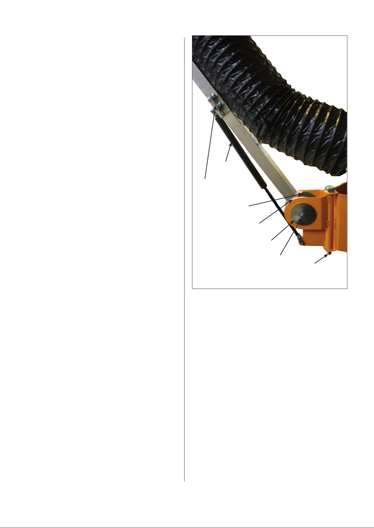
3. Center wrist checked and tightened if needed. Tigh-
ten the joint so that the arm moves freely, but also
so fast that it can sustain itself in a slightly bent
position.
4. Mount the funnel on the outer joint by taking the
supplied M8 bolt through 3 disc springs, the alu
half, the friction disc, the other alu half and the 3
disc springs and fasten them with an M8 lock nut.
5. The hose is mounted on the funnel by tightening the
clamp around the funnel and the hose. Now pull out
the hose to max. so that the least possible resistan-
ce is left in the hose and fasten with the enclosed
plastic binders. Subsequently, the hose is mounted
on the branch pipe by means of the clamp.
2.1 Mounting of optional equipment
Mounting of extension arm
The extension arm for HV50 is available in 1.0 m, 2.5
m and 4.0 m. (4,0 m available in both 1 and 2 line
arm).
1 m extension
Fixing the extension arm to a solid wall, in the same
way as the wall bracket in the section. 2.0.
Then fastened HV50 arm to the extension arm.
2.5 and 4.0 m extension
Attach the wall bracket.
Then install the extension arm
At 4.0 meters 2-leds mounted inner part, then mid link
and eventually outer loops. Ensure that the outer part
is positioned properly during assembly - tube holders
must face up.
Then attach the ducts to the extension arm with the
self-carving screws. The distane between the duct as-
sembled using a Clamp and the hose. The arm is then
fastened to the extension arm.
2.2 Trial run – exact adjustment
After the final mounting, the Arm should be adjusted to
the typical working area, for optimum utilisation of the
Arm. Do so by adjusting the rotary joints mentioned in
item 2 by means of 2 off 13 mm fixed spanners.
3.0 User instruction – application
Operated by the hood. Do not use the arm or hose.
Be especially aware that it is possible to squeeze your
fingers at the gas spring.
Move the hood to the wanted position and wait for the
friction discs to locked the arm.
In normal use, the arm can lift it self in the wanted positi-
on. The arm can rotary 270oin the working space.
The hose can be damaged and leaky by not using it
right, for example a screwdriver. This should be avoided
to ensure a long life span.
Always check that the correct volume of air is extracted
by the suction head/funnel.
Spring damper
Inner joint
ø114 friction bushing
ø80 bell disc
M8 bolt
M16 bolt with friction bushing
Adjustable spring retainer
Adjustable angle of attack