5
5.0 Assembly, installation and start of
operation
5.1 Location
To ensure a flawless function, the product must be in-
stalled indoors in e.g. an engineering room with sound
ventilation.
Outdoor installation is not recommended, and a canopy
must always be used as a minimum if indoor installation
is not possible.
We do not recommend outdoor installation, as the risk
of water and condensation in the product increases, and
the electronic components do not function at temperatu-
res below 5°C.
Before installing the product, ensure that an optimal lo-
cation is chosen. Is there enough space for the product?
Is there space for maintenance and filter changes?
Place the product on a level and stable base (e.g. a con-
crete concrete floor) and secure it.
Avoid as far as possible bends immediately before the
inlet and after the outlet, as this could reduce the perfor-
mance of the product.
5.2 Installation
The following installation should only be carried out by a
trained installer.
5.2.1 Installation
Procedure:
1. Place the HVU Lite on a solid foundation (e.g. a con-
crete floor) where there is no possibility for vibrati-
ons to be transmitted. In addition, allowance shall be
made for filter changes (i.e. minimum headroom of
800 mm).
2. The piping is connected to the HVU Lite. On the inlet
side the pipe can be fixed e.g. by means of a snap
lock system.
Remember to seal the joint with sealant and/or tape!
3. To ensure free mixing, the discharge should be di-
rected two meters above the roof ridge towards the
atmosphere with a discharge velocity of at least 8 m/s.
4. The entire system/piping should always be thorough-
ly inspected for leaks. Leaks must be sealed. The sy-
stem must not be used for the following 24 hours.
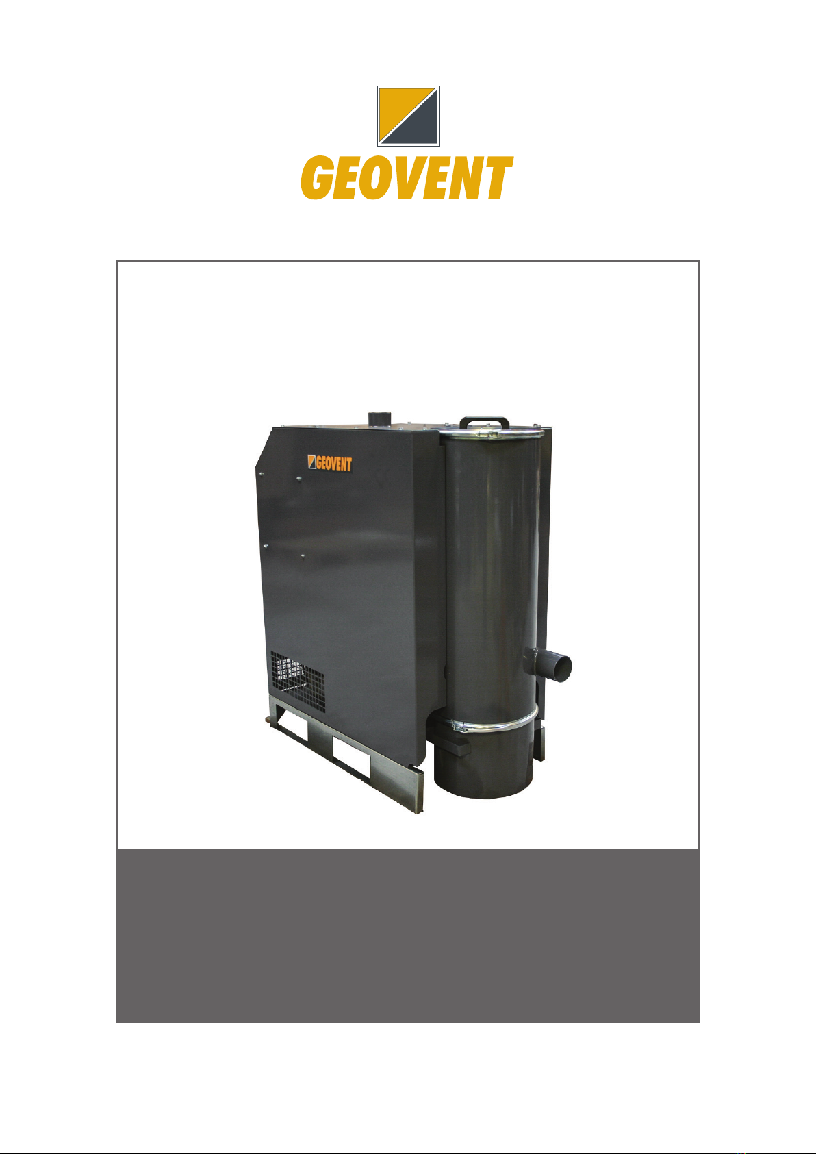
5. It is important to install the product so that it is not
possible for rainwater to penetrate. An example of a
well-functioning installation is shown in this drawing.
Penetrating rainwater can cause the side channel blow-
er to jam and be destroyed.
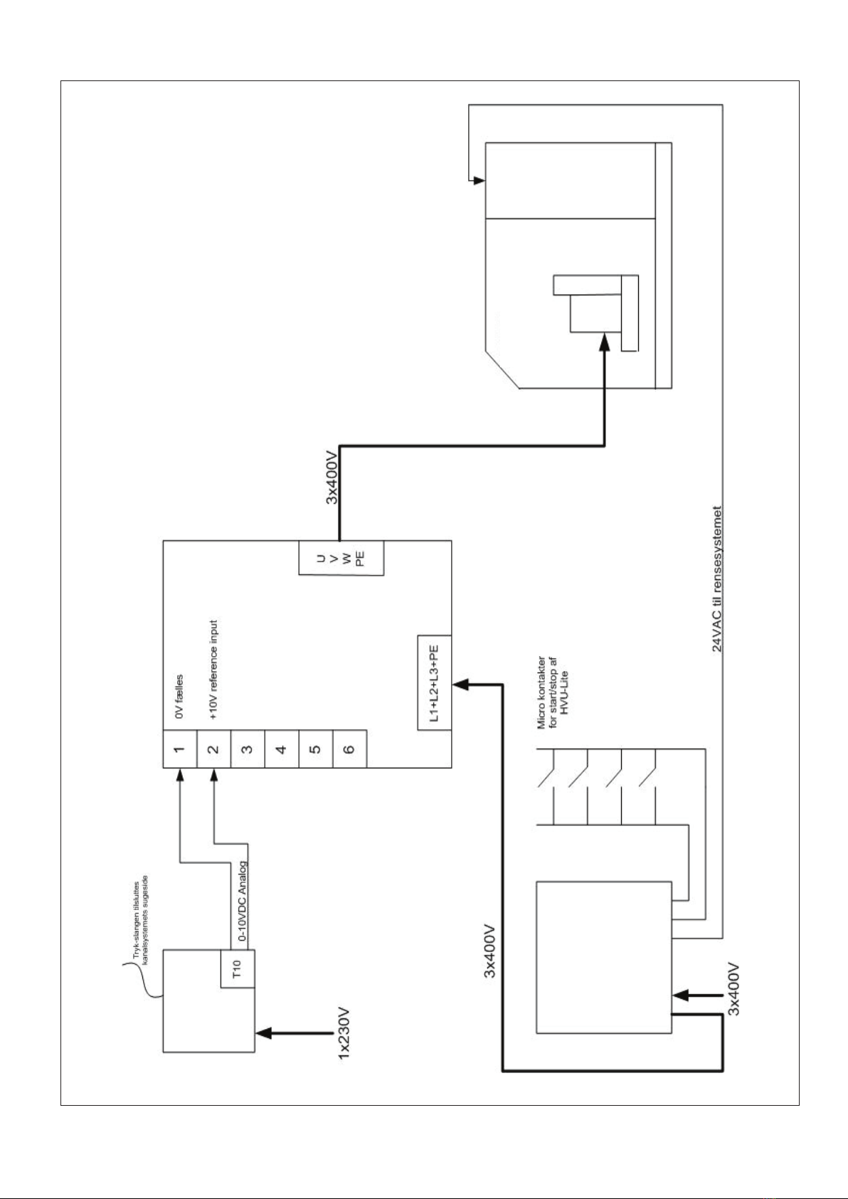
6. The connection of the electrical components of the
HVU Lite should only be carried out by an authorized
electrician.
7. For connection options, see separate panel documen-
tation (located in the panel).
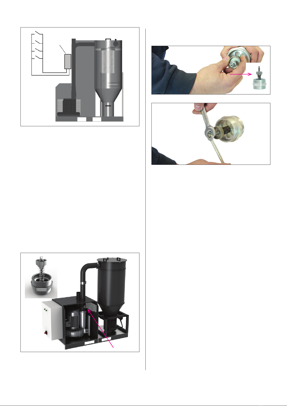
Connection of compressed air:
8. Connect clean and dry compressed air. A pressure
regulator must be installed. We recommend to install
a water separator just before the HVU Lite.
5.2.2 Installation of additional equipment
Mounting of a repair switch
The above principle drawing applies to both HVU and
HVU Lite.
The repair switch must be connected to comply with the
EN 60 204-1 standard, where a manual switch must be
connected. The switch will typically be placed 2 - 3 me-
ters from the unit and must be clearly visible.
Mounting of frequency inverter
We have the possibility to deliver with frequency inverter
and/or pressure control. See manual for pressure con-
trol.
For setting options for external frequency inverter - refer
to the manual of the frequency inverter.
Aftappehane
Luft ind
30 mm isolering
af hensyn til
kondens
Air in
Air out
Drain tap
30 mm insulation
for condensation
Instruktionsmanual Højvakuumunit – HVU-Lite 30 & 55
29-01-2007 ver. 1.0 www.geovent.com Side 3/6
3. For at sikre fri opblanding, bør afkastet føres
to meter over tagryg mod atmosfæren med
en afkast-hastighed på minimum 8 m/s.
4. Hele anlægget/rørføringen bør altid efterses
grundigt for utætheder. Utætheder seales.
Anlægget må ikke anvendes i de
efterfølgende 24 timer.
Tilslutning af ventilator til El-nettet:
5. Tilslutningen af HVU-Lite’ens elektriske
komponenter bør kun udføres af autoriseret
EL-installatør.
6. For tilslutningsmuligheder se diagram side 6.
2.1 Montering af ekstraudstyr
Montering af reparationsafbryder
Her er afbilledet en HVU, men samme gælder for HVU-Lite.
Reparationsafbryder skal tilsluttes for at leve op til
EN 60 204-1 standarden, hvor der skal tilsluttes
en manuel afbryder. Afbryderen vil typisk placeres
2 – 3 meter fra unitten og skal være tydelig synlig.
Flowguard
I Danmark skal alle udsugningsanlæg forsynes
med kontrolanordning til kontrol af korrekt sug iht.
Arbejdstilsynet. Se separat vejledning herom.
Montering af frekvensomformer
For tilslutningsmuligheder for frekvensomformer
se diagram på side 6
For indstillingsmuligheder for ekstern frekvens-
omformer se separat medfølgende manual
(Digidrive).
For detaljere diagram se bilag - bagerste sidst.
2.2 Testkørsel - finjustering
Efter endt installation tjek da, om der er rystelser
eller lydgener ved HVU-Lite’en.
Tjek at hele anlægget er fuldstændigt tæt. Ved
pibelyde, bør utætheden lokaliseres og tætnes
med fugemasse.
Det kan anbefales at tjekke om HVU-Lite’en
levere den luftmængde som anlægget er
dimensioneret til. Mål derfor luftmængden og sørg
for at den ikke overstiger motorens ampere-tal.
3.0 Anvendelse - Brugerinstruktion
HVU-Lite må ikke køre i længere perioder (mere
end 45 min) uden åbne udtag i kanalsystemet, da
pumpen ellers vil overophede og gå i stykker.
Anvend evt. den indbyggede start/stop funktion.
Control panel
3x400V + PE
Repair switch
Pressostat
1x230V
Adjustment of Flowguard
1” Shut-off valve
8mPa (8Bar) clean and
dry compressed air
Flexible connection 1”
compressed air hose
Filter regulator