Geovent HVU 300 User manual

HIGHVACUUM UNIT
HVU 300, 350, 450, 550 and 700
INSTRUCTION MANUAL
www.geovent.com
Version 1.0 08.05.2023

2

3
Contents
1.0 Introduction ..............................3
2.0 Safety ..................................3
2.1 General safety .......................... 3
2.2 Danger .................................3
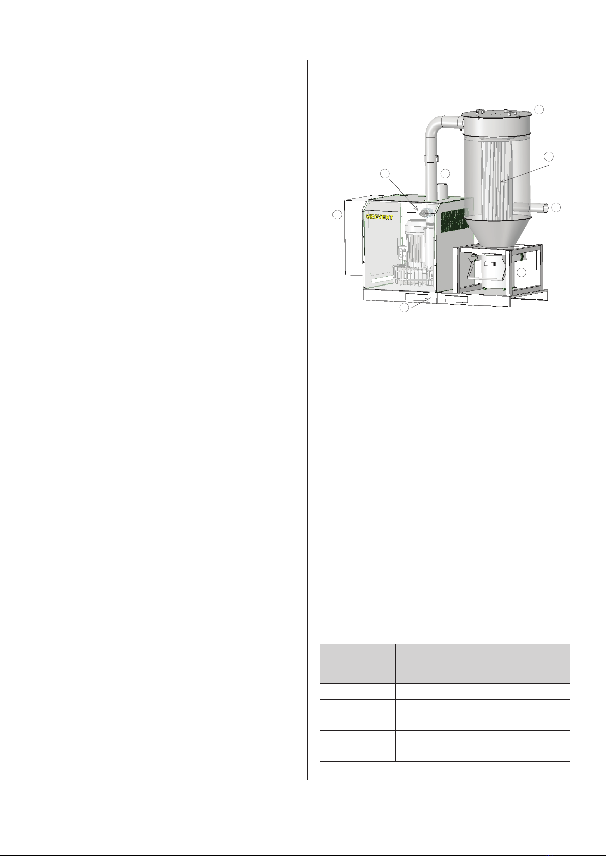
3.0 Machine overview ........................ 4
3.1 Description ............................. 4
3.2 Intended use ............................ 4
3.3 Machine specifications .................... 4
3.3.1 Design ............................... 4
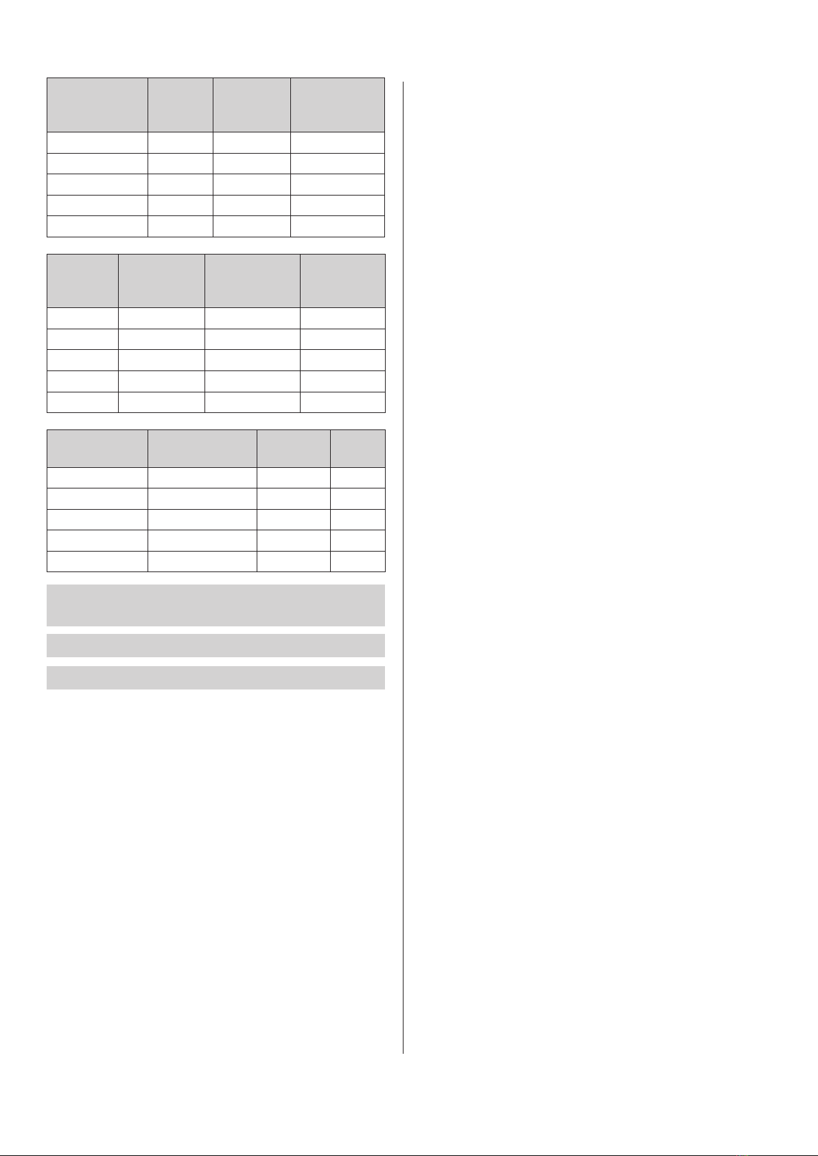
3.3.2 Technical data ......................... 4
4.0 Transport, handling and storage . . . . . . . . . . . . . 5
5.0 Assembly, installation and start of operation ... 5
5.1 Location ............................... 5
5.2 Installation ............................. 5
5.2.1 Installation .............................5
5.2.2 Mountiong of accessories..................6
5.3 Control and test of the system ...............6
6.0 Commissioning .......................... 7
6.1 After installation ......................... 7
7.0 Control, test and maintenance .............. 7
7.1 Control ................................ 7
7.2 Maintenance .............................7
7.3 Replacing filter............................7
7.3.1 Emptying of bucket.......................7
7.3.2 Exchange of filter cartridges................7
8.0 Cleaning ................................7
9.0 Troubleshooting ......................... 7
10.0 Dismantling, disabling and scrapping ........ 8
11.0 Dimensions ............................ 8
12.0 Liability ............................... 9
13.0 Declaration of conformity ................. 9
14.0 Spare part list ......................... 10
1.0 Introduction
This manual is made and designed in order to facilitate
the best and most secure interaction with the product.
The manual is relevant for people involved in transpor-
tation, stocking, installation, using, maintaining and all
other thinkable interaction with the product.
The manual must be read in full and understood before
interacting with the product.
When the manual has been read and understood in full,
the table of contents can be used to find the relevant
information in each case.
The product is manufactured by:
Geovent A/S
Hovedgaden 86
DK-8861 Løgstrup
DENMARK
Tel.: (+45) 86 64 22 11
E-mail: [email protected]
www.geovent.com
This manual is to be used for all interactions with the
product including: Transportation, stocking, installation,
operation and maintenance.
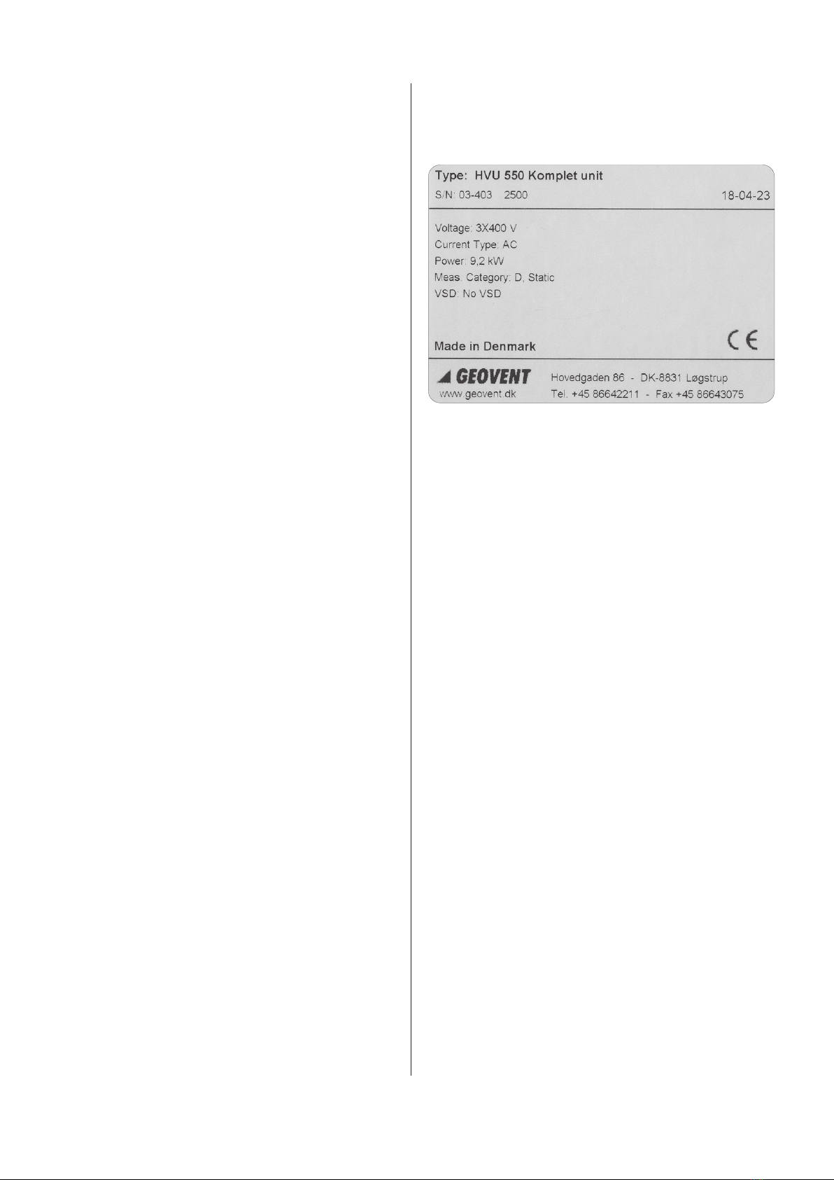
This product is marked with: (example)
2.0 Safety
2.1 General safety
Carefully read this manual before use and observe the
safety instructions in order to avoid injuries!
Keep this manual in a safe place!
Secure that all users of the product have read this ma-
nual and that they follow the instructions as described.
Observe all instructions marked on the product!
Observe the indications of the manufacturer.
Never use the product if you are in doubt about how it
works or what you should do.
When doing maintenance follow the instructions in chap-
ter 7.0.
Do not modify the product or use spare parts from other
suppliers than Geovent, as this may hamper the product
and the function.
2.2 Danger
You must wear safety gloves when handling or using the
product to protect your hands from scratches etc.
Be aware that the product may tilt when you move it.
You must handle the product with care and tie it safely to
the truck or the fork lift when it is in transport.
Follow the instructions in chapter 7.0 when the product
is maintained.
When handling the product be sure that the there is no
risk for the installer, and secure that there are no people
around the product, secure that the product cannot fall
down risking to injure persons or subjects.
In case of an accident or a fire: Call for help.

4
The product is not to be used in areas categorised as
ATEX zones, e.g. with dust from aluminium, flour, wood,
and other mediums that present an explosion hazard.
If a repair is not possible you should dispose of the pro-
duct. Please follow the instruction for disposal in chapter
10.0.
3.0 Machine overview
3.1. Description
The Geovent HVU is a compact high vacuum unit to
collect dust, fumes or other particles. The product is
supplied with dierent characteristics and with dierent
types of accessories.
3.2 Intended use
The Geovent High Vacuum Unit (HVU) is used, among
other things, for vacuuming during car preparation and
for e.g. grinding dust extraction.
The unit is equipped with a two-stage lter cyclone with a
compressed air cleaning system. Filtration degree of
99.9%.
The unit can e.g. be used for extraction of grinding dust
from hand-held rotary sanders, xed belt sanders and
bench grinders, brake dust from cars and trucks as well
as general workplace cleaning etc.
3.3 Machine specifications
3.3.1 Design
A Ø127 mm outlet
B Removable lid
C Control panel with automatic start/stop and filter
cleaning
D Safety valve
E Filter cartridge - Alu-coated polyester fabric - antista-
tic
F Ø127 mm inlet
G Collection bucket 34 liters
H Frame with slots for forklifts
Shield: Coated steel plate.
Filter media: Antistatic aluminum coated polyester fil-
ter with 99.9% filtration efficiency. Life expectancy under
normal use: 4.000-8.000 hours.
Motor/vacuum pump: IP 55 standard motor with side
channel blower in cast aluminum.
Life expectancy in normal use: 20.000 hours
Automation: Control panel in steel IP 54
3.3.2 Technical data
Dimensions
Model Power
[kW]
Power con-
sumption
100% load
Maximum air
flow [m³/h]
HVU 300 7,5 15,5A 562
HVU 350 7,5 15,5A 562
HVU 450 5,5 11,1A 663
HVU 550 9,2 17,8A 782
HVU 700 11 21,6A 939
B
C
D
E
F
H
A
G

5
Model
Max
vacuum
[kPa]
Filter
surface
area [m²]
Filtration
level acc. to
BIA-test
HVU 300 25 12 99,9%
HVU 350 30 12 99,9%
HVU 450 21 12 99,9%
HVU 550 30 12 99,9%
HVU 700 30 12 99,9%
Model
Sound pres-
sure level
ISO 3744
Compressed
air tank 1”
connection
Collection
bucket
HVU 300 74,8 dBA 4 Liter 34 Liter
HVU 350 72,1 dBA 4 Liter 34 Liter
HVU 450 77,1 dBA 4 Liter 34 Liter
HVU 550 77,4 dBA 4 Liter 34 Liter
HVU 700 78 dBA 4 Liter 34 Liter
Model Cabinet + cy-
clone ø700
Corrosion
class Weight
HVU 300 Powder coated ll 210
HVU 350 Powder coated ll 215
HVU 450 Powder coated ll 215
HVU 550 Powder coated ll 225
HVU 700 Powder coated ll 245
Temperature of extracted air Max. 40°C
Ambient temperature -15°C - +40°C
Temperature control panel 5 - 40°C
Relative humidity must be <90%
The sound level depends on several factors. For examp-
le, the location of the high vacuum unit (indoor/outdoor),
the size of the room, the ambient temperature, shotdown
delay and the connection (hose><pipe) of the unit also
have an impact on the sound level.
4.0 Transport, handling and storage
During transport in a truck or in another means of trans-
portation the product must be securely packed in a box
or a pallet and covered with a water proff material.
The product must be securely stowed in the truck so that
it will neither tilt nor shift during transport.
During transport over a short distance e.g. in a stock or
a factory, the product can be moved by means of a for-
klift or a stabeler.
When moved it must be secured that the product does
not tilt or shift. And it must be secured that the limitations
of the means of transportation is not exceeded.
Secure that there are no people around the product,
when the product is moved.
The product must be placed in a dry place and covered
securely, in order to secure that moist, metal parts or
other substances do not damage the product.
It is not allowed to place anything on top of the product.
5.0 Assembly, installation and start of
operation
5.1 Location
To ensure a flawless function, the product must be in-
stalled indoors in e.g. an engineering room with sound
ventilation.
Outdoor installation is not recommended, and a canopy
must always be used as a minimum if indoor installation
is not possible.
We do not recommend outdoor installation, as the risk
of water and condensation in the product increases, and
the electronic components do not function at temperatu-
res below 5°C.
Before installing the product, ensure that an optimal lo-
cation is chosen. Is there enough space for the product?
Is there space for maintenance and filter changes?
Place the product on a level and stable base (e.g. a con-
crete concrete floor) and secure it.
Avoid as far as possible bends immediately before the
inlet and after the outlet, as this could reduce the perfor-
mance of the product.
5.2 Installation
The following installation should only be carried out by a
trained installer.
5.2.1 Installation
Procedure:
1. Place the HVU on a solid foundation (e.g. a concrete
floor) where there is no possibility for vibrations to be
transmitted. In addition, allowance shall be made for
filter changes (i.e. minimum headroom of 800 mm).
2. The piping is connected to the HVU. On the inlet side
the pipe can be fixed e.g. by means of a snap lock
system.
Remember to seal the joint with sealant and/or tape!
3. To ensure free mixing, the discharge should be di-
rected two meters above the roof ridge towards the
atmosphere with a discharge velocity of at least 8 m/s.
4. The entire system/piping should always be thorough-
ly inspected for leaks. Leaks must be sealed. The sy-
stem must not be used for the following 24 hours.

6
5. It is important to install the product so that it is not
possible for rainwater to penetrate. An example of a
well-functioning installation is shown in this drawing.
Penetrating rainwater can cause the side channel blow-
er to jam and be destroyed.
6. The connection of the electrical components of the
HVU should only be carried out by an authorized ele-
ctrician.
7. For connection options, see separate panel documen-
tation (located in the panel).
Connection of compressed air:
8. Connect clean and dry compressed air. A pressure
regulator must be installed. We recommend to install
a water separator just before the HVU.
5.2.2 Mounting of accessories
Mounting of frequency inverter
We have the possibility to deliver with frequency inverter
and/or pressure control. See manual for pressure con-
trol.
For setting options for external frequency inverter - refer
to the manual of the frequency inverter.
Automatic start/stop
External start/stop can be fitted (e.g. micro-switch at
quick coupling/outlet or on/off button on energy arm).
In case of manual operation there is a timer which makes
the HVU switch off automatically after 15-30 minutes.
5.3 Checking and testing the system
After installation, check if there is any vibration or sound
disturbance.
Check that the whole system is completely tight. In case
of squeaking, the leakage should be localized and sea-
led with sealant.
It is recommended to check whether the HVU delivers
the air volume for which the system is dimensioned.
Therefore, measure the air flow and make sure that it
does not exceed the motor’s ampere rating.
Vacuum protection
The valve is roughly adjusted at the factory.
The valve must be readjusted at the installation.
Adjustment of the vacuum safety device
Adjust so that the valve does not open during normal
operation, but opens when blocked.
1. Adjust to loosen or tighten the spring.
2. Then tighten the lock nut to secure the spring
position.
Vacuum protection
Aftappehane
Luft ind
Luft ud
30 mm isolering
af hensyn til
kondens
Air in
Air out
Drain tap
30 mm insulation
for condensation

7
6.0 Commissioning
The HVU must not run for longer periods (max. 15-30
min) without open outlets in the duct system, otherwise
the side channel blower will overheat and break down.
If necessary, use the built-in start/stop function.
After use, it is recommended to keep a flap open for 1-5
seconds, so that particles are sucked away from the ver-
tical piece, and thus do not fall down the next time the
system is used.
6.1 After installation
Check the installation according to chapter 5.3.
7.0 Control, test and maintenance
7.1 Control
Check the installation according to chapter 5.3.
7.2 Maintenance
The entire system should be inspected at least once a
year by a qualified service technician.
Periodic maintenance:
• All electrical parts should be checked annually.
• The annular chamber blower/motor is in principle main-
tenance free due to the factory sealed special ball bea-
rings.
Replacement of worn bearings should only be carried
out by a qualified service technician
7.3 Replacing filter
7.3.1 Emptying of bucket
Emptying of the collection bucket should be done
when it is approx. 2/3 full, otherwise it can strain the
filter medium. The filter medium should be repla-
ced after approx. 4.000 - 8.000 hours of operation
or max. 4 years. This depends, for example, on the load
on the filter.
Procedure:
1. Disconnect the power at the breaker switch. It should
be ensured that the curcuit breaker cannot be acti-
vated during service.
2. Disconnect/remove the compressed air connection.
3. Before dismantling the dusty filter or emptying the
bucket, it is important that the service technician
wears the necessary personal safety measures, such
as respiratory protection and gloves that comply with
relevant regulations for working with contaminated
dust.
4. The collection bucket is then dismantled using the
snap locks. The bucket can then be carefully pulled
out. Empty the bucket into a plastic bag suitable for
the purpose. The bag and the contents must be resto-
red in accordance with the applicable rules.
5. Put the bucket back in place and secure it under the
cyclone.
7.3.2 Exchange of lter cartridges
6. The top/lid of the cyclone is removed by disconnecting
the snap lock, after which the lid with the compressed
air tank is removed. Be careful to disconnect the com-
pressed air and power supply first and not to damage
the compressed air tank when putting it aside.
7. Next, remove the 3 M10 bolts with a 17 mm wrench
that secure the filter media to the unit.
8. Carefully lift the contaminated filter media and place
it in a large waste bag, which is then sealed properly.
9. Insert the new filter media and secure it to the unit with
the 3 M10 bolts.
10.Carefully slide the top/lid into place and secure it
with the snap lock (Remember to connect power and
compressed air!).
11. The contaminated filter media is then restored accor-
ding to local rules and regulations.
8.0 Cleaning
The outside of the product is cleaned with a vacuum
cleaner or a cloth.
9.0 Troubleshooting
In the event that problems occur, the following items
should be reviewed:
Air volume or pressure is less than stated
• Incorrect running direction of the fan wheel.
May be due to incorrect electrical installation.
Double check the direction of rotation. Switch the 2
phases if necessary.
• Leaky duct system.
• Poor inlet/outlet options close to the side channel blow-
er can reduce performance (e.g. 90° bend before inlet)
• Damaged wheel.
• The rotation speed is set too low.
• If the temperature differs significantly from the labora-
tory measurements where the temperature was 20°C
with an atmospheric pressure of 101.4 kPa.
• The dampers are not adjusted correctly.
• The duct or the unit is blocked by e.g. a screwdriver.

8
11.0 Dimensions
HVU
Vibrations and noise
• The foundation is not level/stable.
• External elements have entered the unit/duct system.
• Damaged wheel or motor.
• The wheel is loose.
• The wheel is running in the wrong direction.
• Loose bolts or screws.
The motor is overloaded
•Motor is wired incorrectly.
• Defective motor - contact dealer!
10.0 Dismantling, disabling and scrapping
Deactivate the product by disconnection the electrical
mains. Dismantle compressed air pipes and other pipes
or wires etc. and dispose of it according to local regula-
tions.
Clean the collection bucket and remove the filter cartrid-
ges as described in chapeter 7.3.
Before dismantling the product it is important that the
service technician wears the necessary personal safe-
ty measures, such as respiratory protection and gloves
that comply with the relevant regulations for working
with contaminated dust.
The inside of the product must be cleaned by means of
a vacuum cleaner with a filter which suits the purpose.
Dismantle the metallic parts by unscrewing screws and
bolts. Afterwards cut the larger pieces into smaller pie-
ces and dispose of it according to local regulation.
Dismantle plastic parts and dispose of it according to
local regulations.
Dismantle the electronics, wires and cables and put the-
se into a suitable bag. Afterwards dispose of it according
to local regulations.
The packing material must be sorted according to local
regulations in order to be able to reuse the material.

9
13.0 Declaration of conformity
The manufacturer: GEOVENT A/S
HOVEDGADEN 86
DK-8831 LØGSTRUP
Hereby declares that:
The product: HVU
Model: HVU 300
HVU 350
HVU 450
HVU 550
HVU 700
Complies with the relevant parts of the following directi-
ves and standards:
Directive 2006/42 / EC of the European Parliament and
of the Council of 17 May 2006 on machines and amen-
ding directives 95/16 / EC.
This declaration is no more valid if changes are made to
the product by others than the manufacturer.
Authorized to collect the technical file:
Lise Cramer
Date: 08.05.2023
Position: Director
Name: Thomas Molsen
Signature: ____________________________
12.0 Liability
Warranty
Geovent A/S grants a warranty for products, which are
defective, when it can be proved that the defects are due
to poor manufacture or materials on the part of Geovent.
The warranty comprises remedial action (reparation or
exchange) until one year after the date of shipment.
No claims can be made against Geovent A/S in relation
to loss of earnings or consequential loss as a result of
defects on products from Geovent.
Wear on parts such as filter cartridges and hose is not
included in the warranty.
User liability
In order for Geovent to be capable of granting the decla-
red warranty, the user/fitter must follow this instruction
manual in all respects.
Under no circumstances may the products be chan-
ged in any way, without prior written agreement with
Geovent A/S.
Please refer to the current sales and delivery conditions
at www.geovent.com

10
14.0 Spare part list
Art. No. Description
92-211 Breaker switch 16A
03-260 Replacement cartridge ø225 for HVU
- 5 m²
13-700A MultiBox for high vacuum 30 kPa
0-10V
13-727 AirBox Lite HV

1111
This manual suits for next models
4
Table of contents
Other Geovent Vacuum Cleaner manuals