7
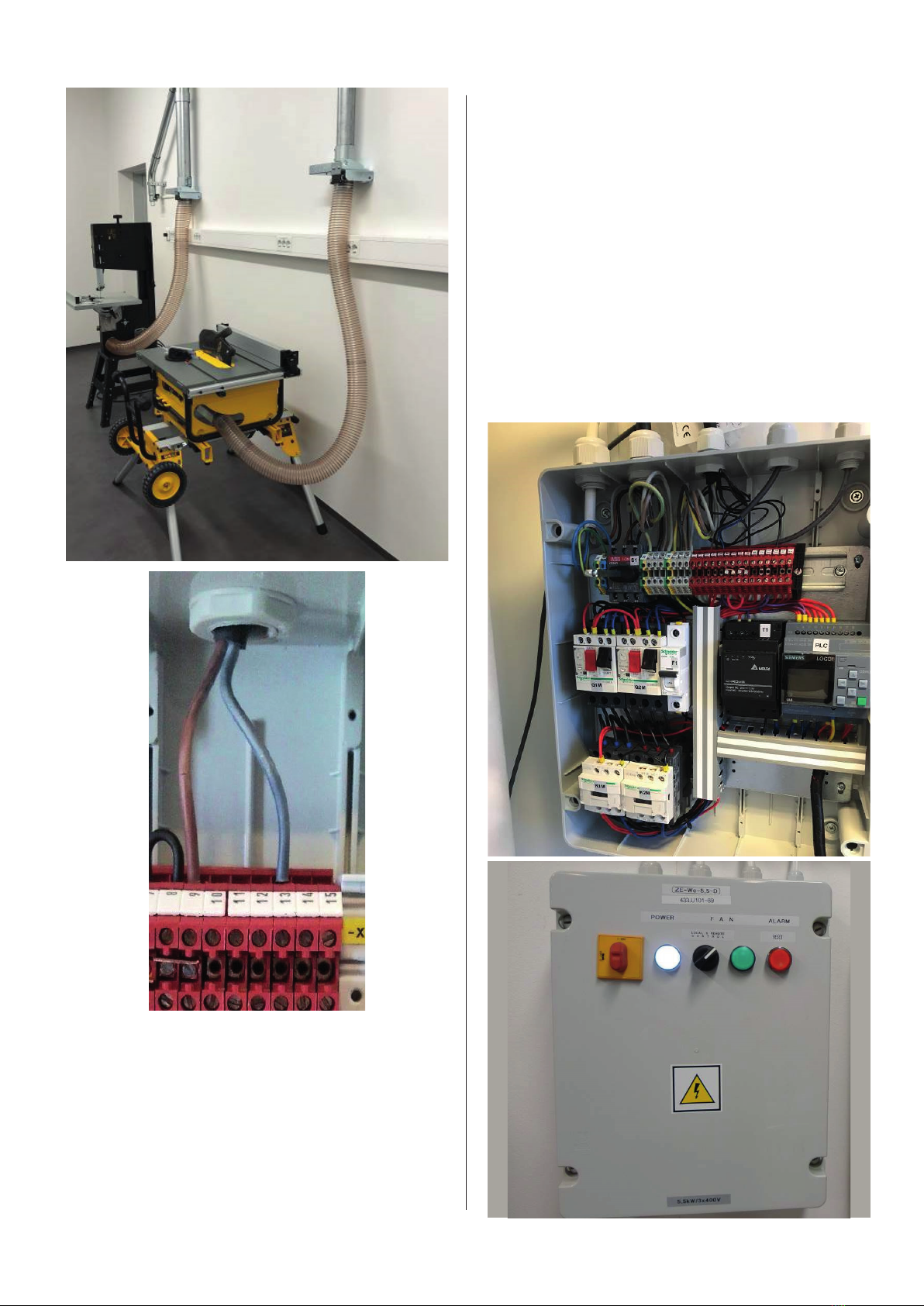
A silencer (900/1200 mm – Ø200/250) and a spiro for
the outdoors are recommended on the return (Ø200/250
mm recommended). Electrical work must be carried out
by certied personnel in accordance with current regu-
lations.
See also chapter 5.
Before starting, check the following:
- Correct supply voltage and grounding
- Correct connection of phases on the motor, correctly
set motor protection, correctly secured main course
- Check the physical direction of rotation of the fan. If the
impeller has the wrong direction of rotation, the suction
is poor.
- Check motor protection settings, are these set slightly
above the rated current on motors?
- Check that all microswitches are correctly connected
on the panel
- Correct attachment of the bag lter and the waste bag
- Doors closed and tightened (“false” air can cause the
bag to be sucked up and sound the alarm)
- KCapacitive sensor must be adjusted correctly. The ad-
justment screw for sensitivity is under the black cover
screw.
- Test the device by setting the black switch to the
“Local” position
- Filter cleaner takes approx. 20 seconds after stopping
- Put the black switch in “Remote” and test start and stop
from dampers/valves/micro switches
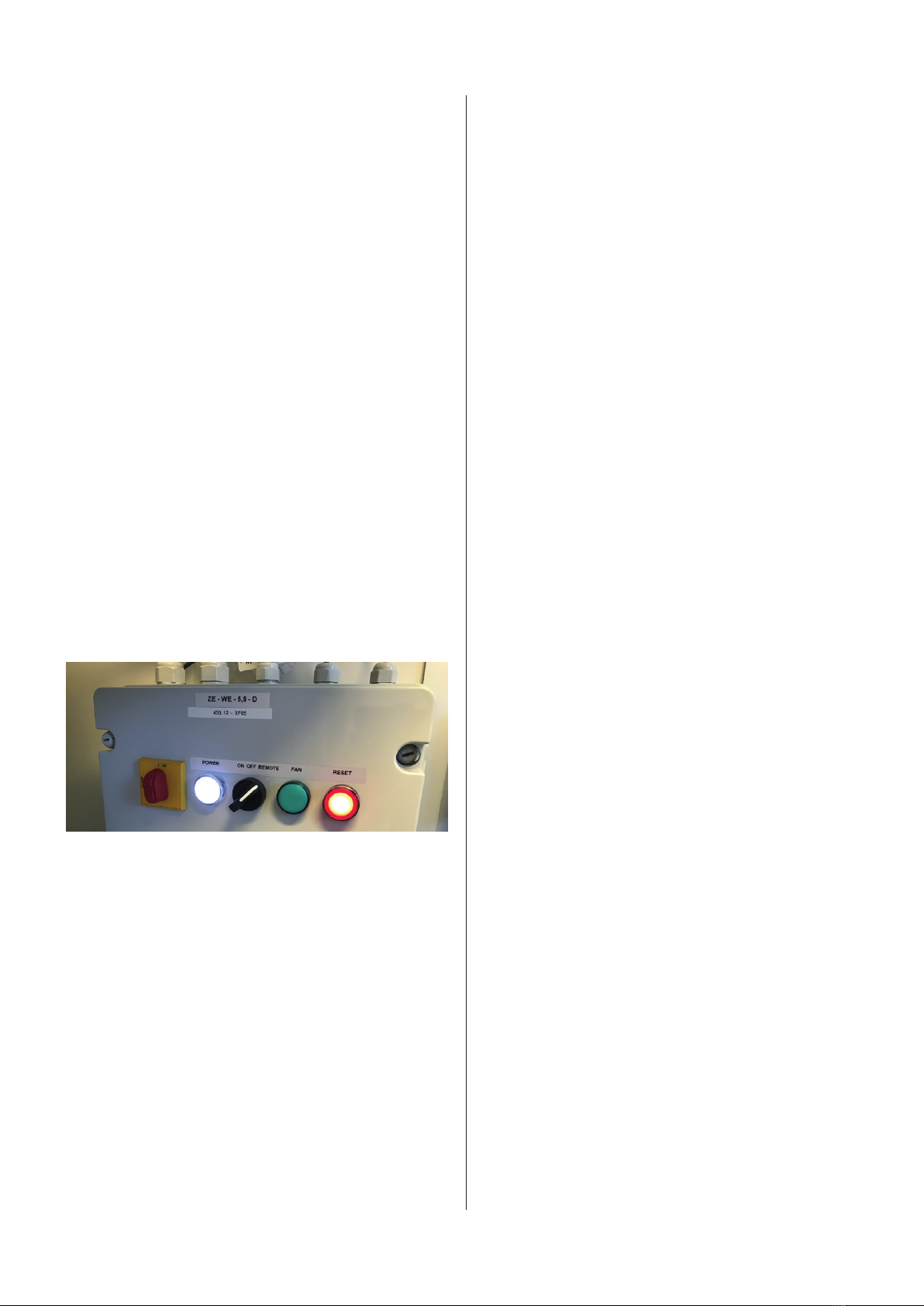
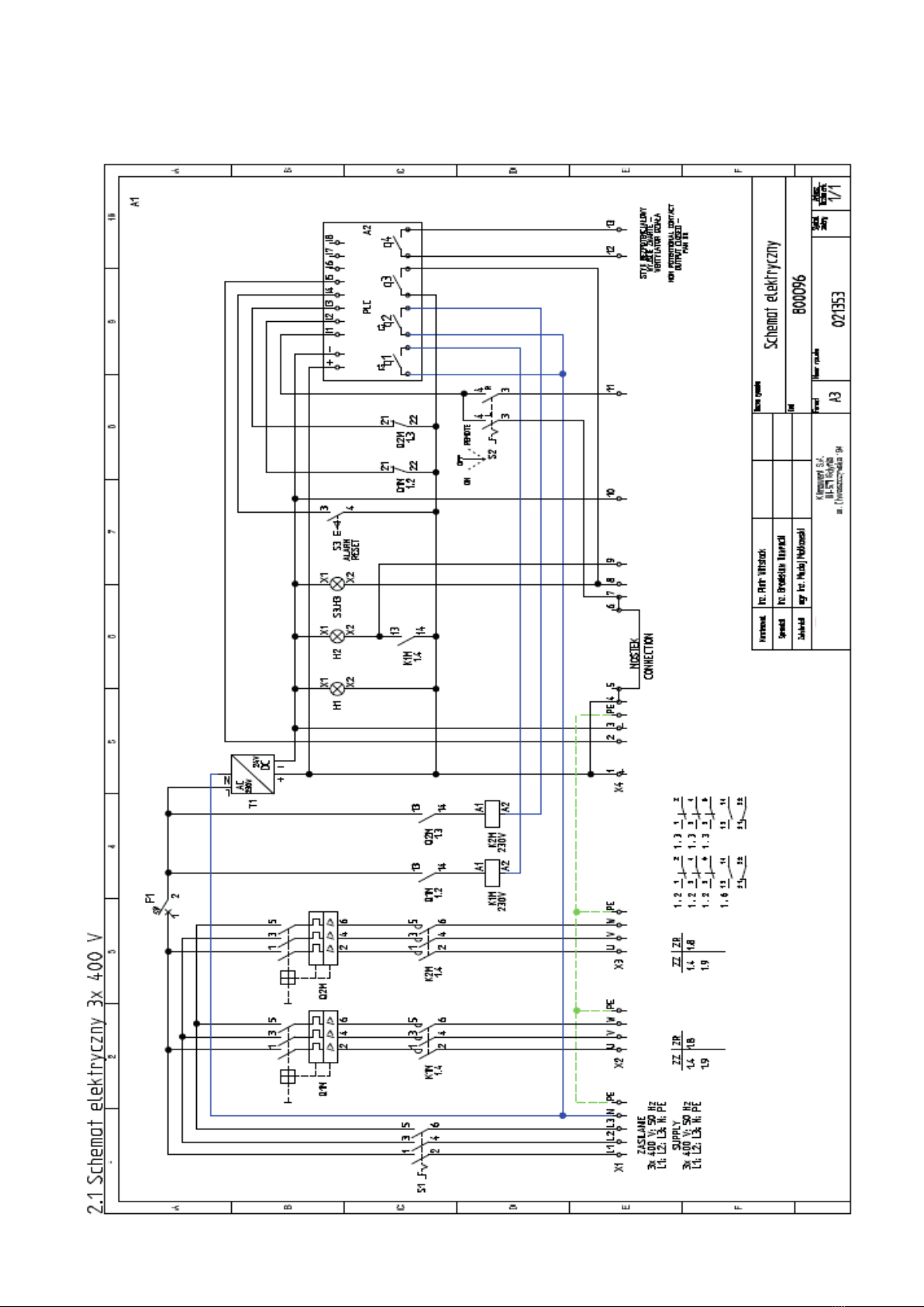
7 Use, application and alarms
Connection of the main switch, the unit in stand-by
Turn the red switch to the “ON” position
- The yellow lamp (-H1) lights up.
Start of fan/extraction - test run
Turn the black control switch to the “Local” position to
start the test. The fan starts, indicated by a lit white sig-
nal lamp. Then set the black switch to the “Remote” po-
sition.
Operation/remote control of the unit
For automatic operation of the unit, set the red switch
to “On” and the black switch to “Remote”. The unit must
now be started and stopped when sliding dampers and
ap valves are used. Micro switches must be connected.
Disconnection of Aggregate:
To stop the unit, set the red switch (-S2) to position
“OFF” and then
turn the switch (-S1) to the “OFF” position.
Full-bag alarm (steady red light):
When the waste bag is full, or the capacitive sensor de-
tects something in front (for example a waste bag), the
red lamp (- H3) “ALARM” lights up. The fan is stopped,
the bag must be emptied or the obstruction must be re-
moved, the alarm can be reset and the system starts
again.
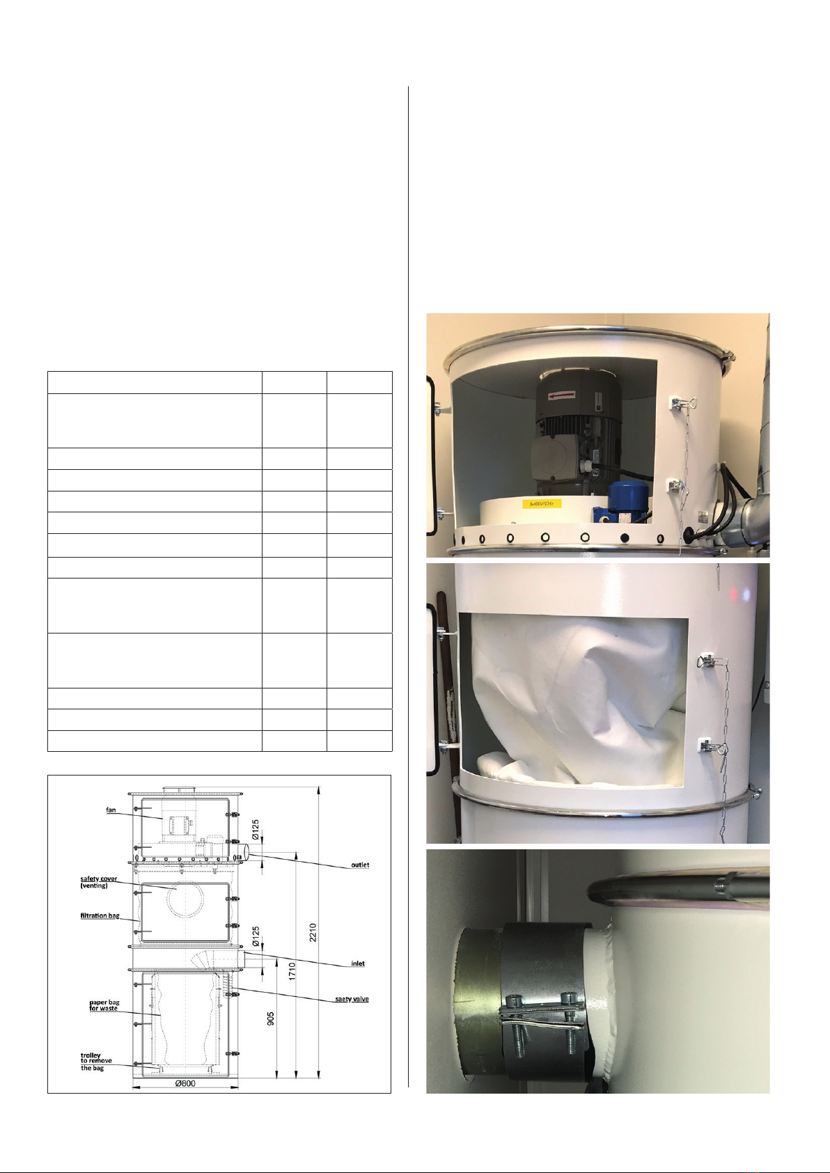
For emptying the bag; Open the bottom door, pull out the
trolley with the waste bag to change the bag.
Clean any capacitive sensor.
Replace the waste bag with a new one, place the trolley
into the unit, lift the bag into place with the weight arms
of the trolley, close the door properly.
NB! Clean properly if there are chips around the door/
gasket. False air will cause the bag to be sucked up and
trigger the alarm again!
Under normal conditions, the shaking motor starts and
shakes the lter for approx. 20 seconds each time the
unit is stopped. The shaking removes ne dust from the
bag lter and gives a longer lter life.
Error - motor protection tripped (ashing red light)
In the event of a fault on the motor protection switch
(-Q1) or (-Q2), the lamp (-H3) “ALARM” ashes. The fan
then switches o automatically. Check the switch and
electrical connections, then start the fan by pressing the
(-S3) “RESET” button.
Examples of incorrect use and incorrect operating
areas:
a. Dust and gases beyond temperatures -20°C to 40°C.
b. Extraction of explosive dust and gases
c. Extraction of aggressive, damp or sticky media
d. Extraction of gas, smoke or dust below 10 microns
e. Extraction from hot processes (metal grinding)
Possible consequences of incorrect use:
- Clogged lters
- Damage to bearings and axles
- Corrosion damage
- Imbalance on fan, impeller
- Vibrations and damage to the shaker motor
- Deformations and fatigue fractures
- Damage due to friction
- Sparks and ignition sources can cause ignition
8 Problem solving
Always switch o the power before working on the unit,
motor, electrics, impeller etc.
Extraction disappears while the fan is running.
Clogging in the suction channel, at a branch etc. Must be
opened and cleaned
Fan stops
Check motor, impeller, supply, fuse. Contact an elec-
trician. Regarding fan motor must be checked by the
manufacturer/specialist. Check any alarms (full bag or
engine protection)
Vibrations
Check the impeller for dirt or damage. Check engine for
bearing noise.